
Related Manuals for ETS-Lindgren 1052


Summary of Contents for ETS-Lindgren 1052
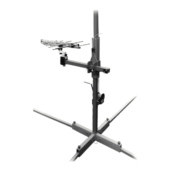
- Page 1 Model 1052 Antenna Tower Positioning System User Manual (Antenna not included)
- Page 2 ETS-Lindgren L.P. reserves the right to make changes to any product described herein in order to improve function, design, or for any other reason. Nothing contained herein shall constitute ETS-Lindgren L.P. assuming any liability whatsoever arising out of the application or use of any product or circuit described herein.
-
Page 3: Table Of Contents
Table of Contents Notes, Cautions, and Warnings ..........v 1.0 Introduction ................7 ETS-Lindgren Product Information Bulletin ........... 7 2.0 Maintenance ................. 9 Annual Calibration ..................9 Service Procedures ..................9 3.0 Specifications ..............11 ... - Page 4 This page intentionally left blank.
-
Page 5: Notes, Cautions, And Warnings
Included text gives proper procedures. Warning: Denotes a hazard. Failure to follow instructions could result in SEVERE personal injury and/or property damage. Included text gives proper procedures. See the ETS-Lindgren Product Information Bulletin for safety, regulatory, and other product marking information. - Page 6 This page intentionally left blank.
-
Page 7: Introduction
The base is an aluminum four-leg design for maximum support and portability. The design of the Model 1052 allows easy assembly and usage. ETS-Lindgren Product Information Bulletin See the ETS-Lindgren Product Information Bulletin included with your shipment for the following: •... - Page 8 This page intentionally left blank. Introduction...
-
Page 9: Maintenance
See the Product Information Bulletin included with your shipment for information on ETS-Lindgren calibration services. Service Procedures For the steps to return a system or system component to ETS-Lindgren for service, see the Product Information Bulletin included with your shipment. Maintenance... - Page 10 This page intentionally left blank. Maintenance...
-
Page 11: Specifications
3.0 Specifications Load Capacity Maximum Carrier Load Capacity On Tip of Cross Boom: 11.3 kg (24.91 lb) On Center of Cross Boom: 22.7 kg (50.04 lb) Physical Specifications Nominal Height: 4 m (13.12 ft) Overall Height: 7 m (22.96 ft) Weight: 34.47 kg (76.0 lb) Specifications... - Page 12 This page intentionally left blank. Specifications...
-
Page 13: Assembly Instructions
ETS-Lindgren Product Information Bulletin included with your shipment. Prior to assembly and operation of the Model 1052 Antenna Tower Positioning System, read Operation on page 21. 1. Attach lower mast section to base assembly—Install the lower mast onto the center post of the base assembly, aligning the markers. - Page 14 The rope clamp is located on a wire (as shown) for shipping purposes only. During step 6 of the assembly instructions you will move the rope clamp to the rope. 2. Attach winch assembly to lower mast section • Install the winch assembly onto the lower mast with the crank side of the winch aligned with the marker on mast.
- Page 15 • Secure winch with winch lock pin by sliding the pin through the winch and mast. Assembly Instructions...
- Page 16 3. Slide carrier assembly onto lower mast. • Carefully place the mast and base assembly onto the side. • Slide the carrier assembly over the lower mast. • The carrier assembly and boom collar/brackets should face away from the winch. The long side of the carrier assembly should face upward. Assembly Instructions...
- Page 17 4. Install upper mast section—With the pulley at the top, insert the upper mast into the lower mast, and align the markers. 5. Thread winch rope from winch, through pulley, and down the other side to the carrier. • Remove the clevis pin at the top of the upper mast.
- Page 18 • Continue to unwind rope until there is enough rope to reach the winch. • Secure the rope with a loop to the carrier assembly at the boom brackets. Use the rope clamp to secure. Assembly Instructions...
- Page 19 6. Move rope clamp from shipping wire to rope. • Remove the four bolts from the rope clamp to separate the two pieces. • About two inches above where the rope is secured at the boom brackets, place one piece of the rope clamp on each side of the rope. •...
- Page 20 8. Install extension legs. • Position the carrier at the winch assembly. • Raise the entire unit until it is in an upright position, resting on the base. • Install the extension legs into the base with each leg oriented so the pin hole is nearest to the bottom side of the leg.
-
Page 21: Operation
5.0 Operation Before You Begin Before placing into operation, follow the safety information in the ETS-Lindgren Product Information Bulletin included with your shipment. Follow these guidelines prior to operating the Model 1052. • Make sure that the winch is always securely fastened to the mast. -
Page 22: Using Guy Ropes
Additional rope is included with your Model 1052 Antenna Tower Positioning System for installing guy ropes. You should use guy ropes for extra mast stability when using the Model 1052 outside, with heavy loads, and other situations when extra stability is required. -
Page 23: Appendix A: Warranty
Appendix A: Warranty See the Product Information Bulletin included with your shipment for the complete ETS-Lindgren warranty for your Model 1052 Antenna Tower Positioning System. 1052 URATION OF ARRANTIES FOR ODEL All product warranties, except the warranty of title, and all remedies for warranty failures are limited to two years.
Need help?
Do you have a question about the 1052 and is the answer not in the manual?
Questions and answers