Table of Contents
Advertisement
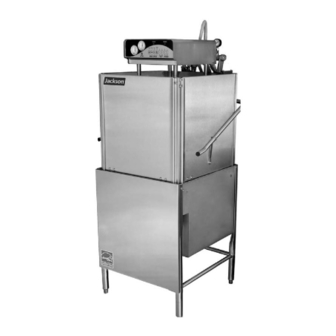
TEMPSTAR SERIES UPRIGHT DOOR DISHMACHINES
INSTALLATION/OPERATION
& TECHNICAL MANUAL
ELECTRICALLY HEATED MODELS:
TEMPSTAR
TEMPSTAR LT
TEMPSTAR NB
TEMPSTAR SDS
STEAM HEATED MODELS:
TEMPSTAR S
Jackson MSC, LLC.
P.O. BOX 1060
HWY. 25E
BARBOURVILLE, KY. 40906
PHONE (606) 523-9795
December 07, 2007
FAX (606) 523-9196
P/N 7610-011-86-35 (Revision K)
www.jacksonmsc.com
Advertisement
Chapters
Table of Contents

Subscribe to Our Youtube Channel
Related Manuals for Jackson Upright Door Dishmachines Tempstar Series


Summary of Contents for Jackson Upright Door Dishmachines Tempstar Series
- Page 1 & TECHNICAL MANUAL ELECTRICALLY HEATED MODELS: TEMPSTAR TEMPSTAR LT TEMPSTAR NB TEMPSTAR SDS STEAM HEATED MODELS: TEMPSTAR S Jackson MSC, LLC. P.O. BOX 1060 HWY. 25E BARBOURVILLE, KY. 40906 PHONE (606) 523-9795 December 07, 2007 FAX (606) 523-9196 P/N 7610-011-86-35 (Revision K)
-
Page 3: Manufacturers Warranty
The warranty registration card supplied with the machine must be returned to Jackson MSC within 30 days to validate the warranty. REPLACEMENT PARTS WARRANTY Jackson replacement parts are warranted for a period of 90 days from the date of installation or 180 days from the date of shipment from the factory, which ever occurs first. - Page 4 STOP! PARE! ARRET! CALL 1-888-800-5672 TO REGISTER THIS PRODUCT! FAILURE TO DO SO WILL VOID THE WARRANTY! LLAME AL 1-888-800-5672 PARA REGISTRAR ESTE PRODUCTO! AL NO HACERLO LA GARANTIA SERA ANULADA! S.V.P . APPELER 1-888-800-5672 POUR ENREGISTRER CE PRODUIT, LA GARANTIE SERA ANNULEE POUR TOUT PRODUIT NON- ENREGISTREE...
- Page 5 REVISION MADE REVISION DATE 05-14-04 01-05-05 01-17-06 02-07-06 06-26-06 12-07-07 APPLICABLE 6964 Changed thermostat. Changed thermostat mounting bracket. 7006 Change to new layout. Added note for “wye configuration”. Added Overflow Lift Brackets. Added Right False Panel 7084 Weldment used with overflow tube lifter. Added universal False 6690 Panel Weldment for Tempstars.
- Page 6 Service Rep. Name: Phone No.: TEMPSTAR NB Jackson MSC LLC. provides technical support for all of the dishmachines detailed in this manual. We strongly recommend that you refer to this manual before making a call to our technical support staff.
-
Page 7: Table Of Contents
Section Description Specifications Operating Capacities Electrical Requirements Dimensions Tempstar/Tempstar LT/Tempstar NB (Side Mounted Control Box) Dimensions Tempstar/Tempstar LT/Tempstar NB (Top Mounted Control Box) Dimensions Tempstar SDS Table Dimensions Installation/Operation Instructions Installation Instructions Electrical Installation Instructions Operation Instructions Detergent Control False Panel Installation III. - Page 8 Tempstar SDS 380/440/460V, 50/60 Hz, three phase Tempstar SDS 380/415V, 50 Hz, three phase, 5 wire Tempstar SDS Dispenser VI.C Electrical Diagram Options Safety Door Interlock (SDI) Drain Quench Exhaust Fan Control VII. Jackson Maintenance & Repair Centers TABLE OF CONTENTS...
-
Page 9: Section 1: Specification Information
SECTION 1: SPECIFICATION INFORMATION... -
Page 10: Operating Capacities
SECTION 1: SPECIFICATION INFORMATION PERFORMANCE/CAPABILITIES OPERATING CAPACITY: RACKS PER HOUR DISHES PER HOUR GLASSES PER HOUR OPERATING CYCLE (SECONDS): MINIMUM (OTHER CYCLE TIMES ARE AVAILABLE) WASH TIME RINSE TIME DWELL TIME TOTAL CYCLE TIME TANK CAPACITY: WASH TANK (GAL) WASH TANK (L) RINSE TANK (TEMPSTAR/TEMPSTAR SDS) (GAL) 3.0 RINSE TANK (TEMPSTAR/TEMPSTAR SDS) (L) STEAM REQUIREMENTS:... - Page 11 SECTION 1: SPECIFICATION INFORMATION NOTE: Typical Electrical Circuit is based upon (1) 125% of the full amperage load of the machine and (2) typical fixed-trip circuit breaker sizes as listed in the NEC 2002 Edition. Local codes may require more stringent protection than what is displayed here.
-
Page 12: Dimensions Tempstar/Tempstar Lt/Tempstar Nb (Side Mounted Control Box)
SECTION 1: SPECIFICATION INFORMATION DIMENSIONS TEMPSTAR/TEMPSTAR LT/NB (SIDE MOUNTED CONTROL BOX) 25 1/4” (64.1 cm) 32” (81.3 cm) LEGEND: A- WATER INLET (3/4” NPT) B- ELECTRICAL CONNECTION POINT 76” (193 cm) W/ DOOR OPEN 17 1/2” (44.5 cm) MACHINE OPENING 34”... -
Page 13: Dimensions Tempstar/Tempstar Lt/Tempstar Nb (Top Mounted Control Box)
SECTION 1: SPECIFICATION INFORMATION DIMENSIONS TEMPSTAR/NB/LT/S (TOP MOUNTED CONTROL BOX) A- WATER INLET (3/4” NPT) B- ELECTRICAL CONNECTION POINT C- DRAIN (1 1/2” NPT) 25 1/4” (64.1 cm) 32” (81.3 cm) LEGEND D- STANDARD CLEARANCE BETWEEN MACHINE AND WALL (WITH DISHTABLE) IS 4” (10.2 cm). 4 7/8”... -
Page 14: Dimensions Tempstar Sds
SECTION 1: SPECIFICATION INFORMATION A- WATER INLET (3/4” NPT) B- ELECTRICAL CONNECTION POINT C- DRAIN (1 1/2” NPT) 25 1/4” (64.1 cm) 32” (81.3 cm) 74” (188 cm) DIMENSIONS TEMPSTAR SDS D- STANDARD CLEARANCE BETWEEN MACHINE AND WALL (WITH DISHTABLE) IS 4” (10.2 cm). E- CHEMICAL DISPENSING SYSTEM 76”... -
Page 15: Table Dimensions
SECTION 1: SPECIFICATION INFORMATION TABLE DIMENSIONS 4” (10.2 cm) MINIMUM TABLE DIMENSIONS CORNER INSTALLATION 20 1/2” (52.1 cm) 2 1/2” (6.4 cm) OPENING 25 1/4” 4” (10.2 cm) (64.1 cm) MINIMUM 3/4” (1.9 cm) 1 1/2” (3.81 cm) ROLL TABLE DIMENSIONS 20 1/2”... -
Page 16: Section 2: Installation/Operation Instructions
SECTION 2: INSTALLATION/OPERATION INSTRUCTIONS... -
Page 17: Installation Instructions
However, rough handling by carriers or others may result in there being damage to the unit while in transit. If such a sit- uation occurs, do not return the unit to Jackson; instead, contact the carrier and ask them to send a representative to the site to inspect the damage to the unit and to complete an inspection report. -
Page 18: Electrical Installation Instructions
SECTION 2: INSTALLATION/OPERATION INSTRUCTIONS INSTALLATION INSTRUCTIONS (CONTINUED) PLUMBING CHECK: Slowly turn on the water supply to the machine after the incoming fill line and the drain line have been installed. Check for any leaks and repair as required. All leaks must be repaired prior to placing the machine in operation. ELECTRICAL POWER CONNECTION: Electrical and grounding connections must Power Block Ground Lug... -
Page 19: Operation Instructions
SECTION 2: INSTALLATION/OPERATION INSTRUCTIONS PREPARATION: Before proceeding with the start-up of the unit, verify the following: 1. The pan strainer and pump suction strainer are in place and are clean. 2. The overflow tube and o-ring are installed. 3. That the wash and rinse arms are screwed securely into place and that their endcaps are tight. The wash and rinse arms should rotate freely. -
Page 20: Detergent Control
If the water cannot get hot enough, your results may not be satisfactory. This is why Jackson recommends that if you have installed the machine in an area with hard water, that you also install some type of water treatment equipment to help remove the dissolved solids from the water before it gets to the dishmachine. -
Page 21: False Panel Installation
SECTION 2: INSTALLATION/OPERATION INSTRUCTIONS False Panel Insert this side first. Bottom of side panel. FALSE PANEL INSTALLATION 1. Remove the rack assembly from the unit. 2. False panel will mount inside the dishmachine. 3. Position panel in unit on side to be closed. 4. -
Page 22: Section 3: Preventative Maintenance
SECTION 3: PREVENTATIVE MAINTENANCE... - Page 23 The dishmachines covered in this manual are designed to operate with a minimum of interaction with the operator. However, this does not mean that some items will not wear out in time. Jackson highly recommends that any maintenance and repairs not specifically discussed in this manual should be performed by QUALIFIED SERVICE PERSONNEL ONLY.
-
Page 24: Section 4: Troubleshooting Section
SECTION 4: TROUBLESHOOTING SECTION... -
Page 25: Common Problems
WARNING: Inspection, testing and repair of electrical equipment should only be performed by a qualified service technician. Many of the tests require that the unit have power to it and live electrical components be exposed. USE EXTREME CAUTION WHEN TESTING THE MACHINE. Problem: Dishmachine will not fill after the door is close. - Page 26 WARNING: Inspection, testing and repair of electrical equipment should only be performed by a qualified service technician. Many of the tests require that the unit have power to it and live electrical components be exposed. USE EXTREME CAUTION WHEN TESTING THE MACHINE. Problem: Doors will not close completely.
-
Page 27: Section 5: Parts Section
SECTION 5: PARTS SECTION... -
Page 28: Top Mounted Control Box Assembly (Universal Timer)
SECTION 5: PARTS SECTION TOP MOUNTED CONTROL BOX ASSEMBLY WITH UNIVERSAL TIMER Tempstar LT/NB/S/SDS Technical Manual 7610-011-86-35 Issued: 12-07-2007 Revised: N/A... - Page 29 TOP MOUNTED CONTROL BOX ASSEMBLY WITH UNIVERSAL TIMER (CONTINUED) ITEM DESCRIPTION Control Box Weldment Timer Bracket Locknut, 6-32 S/S Hex w/Nylon Insert Contactor, 4 Pole Terminal Block Locknut, 10-24 S/S Hex w/Nylon Insert Contactor, Wash Motor 208-230, 30Amp Switch, 8 Button Holder, Keystone Timer, Universal Relay, All Voltages...
-
Page 30: Top Mounted Control Box Assembly (Mechanical Timer)
SECTION 5: PARTS SECTION TOP MOUNTED CONTROL BOX ASSEMBLY (MECHANICAL TIMER) Tempstar LT/NB/S/SDS Technical Manual 7610-011-86-35 Issued: 12-07-2007 Revised: N/A... - Page 31 TOP MOUNTED CONTROL BOX ASSEMBLY (MECHANICAL TIMER) (CONTINUED) ITEM DESCRIPTION Control Box Weldment Ground Lug Terminal Block Terminal Block (415V, 3PH, 5 Wire Only) Contactor, Wash Motor 208-230 Contactor, Wash Motor (380, 415, 440, 460 Volt Units) Overload, 1.7-2.6 (380, 415, 440, 460 Volt Units) Relay, All Voltages Relay, (415V, 3PH, 5 Wire Only) Counter...
-
Page 32: Side Mounted Control Box Assembly
SECTION 5: PARTS SECTION SIDE MOUNTED CONTROL BOX ASSEMBLY 2, 21 7, 8 CONTROL BOX FRONT COVER Cover, Dielectric Control Panel 05700-021-50-89 Bracket, Side Mount Electrical Box 05700-041-65-68 Tempstar LT/NB/S/SDS Technical Manual 7610-011-86-35 9, 22 10, 22 INNER CONTROL BOX LAYOUT CONTROL BOX BOTTOM LAYOUT The mounting screws for the control box front cover (10-32 X 1/2”... - Page 33 SIDE MOUNTED CONTROL BOX ASSEMBLY (CONTINUED) ITEM DESCRIPTION Power Switch Cycle Counter Normal/Delime Switch Power Light High Limit Light Cycle Light Decal, Control Box Cover Control Box Cover Relay, Top Mount, Control Fuse Holder Timer, 60 Hz Timer, 50 Hz Contactor, 220V, 4 Pole (1 for Tempstar NB models) Liquid Level Control Board Screw, 6-32 x 5/8"...
-
Page 34: Sds Control Box Assembly
SDS SIDE MOUNTED CONTROL BOX ASSEMBLY Cover, Dielectric Control Panel 05700-021-50-89 Bracket, Side Mount Electrical Box 05700-041-65-68 SECTION 5: PARTS SECTION Tempstar LT/NB/S/SDS Technical Manual 7610-011-86-35 Issued: 12-07-2007 Revised: N/A... - Page 35 SDS SIDE MOUNTED CONTROL BOX ASSEMBLY (CONTINUED) ITEM DESCRIPTION Control Box Cover Weldment Decal, Control Box Cover Light, Amber Light, Green Light, Red Manual Wash Switch Screw, 4-40 x 1/4" Phillips Panhead Cycle Counter Wash Switch Screw, 10-32 x 3/8" Phillips Panhead Cover, Electrical Box Panel Frame, Electrical Box Cover Panel Board, PC Rinse...
-
Page 36: Hood Assembly
Switch Box Weldment 05700-002-14-34 SDS Switch Box Weldment 05700-002-30-98 ITEM DESCRIPTION Hood Weldment (Tempstar/Tempstar LT/Tempstar NB) Hood Weldment (Tempstar SDS) Left Front Hood Support Right Front Hood Support Double Door Guide, Front Left Double Door Guide, Front Right Guide, Right Rear Guide, Left Rear Screw, 1/4"-20 x 1/2"... -
Page 37: Hood Assembly (Bolted Single Support Design)
HOOD ASSEMBLY (BOLTED SINGLE SUPPORT DESIGN) ITEM DESCRIPTION Hood Weldment (Tempstar/Tempstar LT/Tempstar NB) Hood Weldment (Tempstar SDS) Hood Support Bolt, 1/4”-20 x 1/2” Long Washer, Flat, SS, 1/4”-20 ID Locknut, 1/4”-20 with Nylon Insert (Not Shown) Block Spacer SECTION 5: PARTS SECTION Tempstar LT/NB/S/SDS Technical Manual 7610-011-86-35 Issued: 12-07-2007 Revised: N/A Mfg. -
Page 38: Cantilever Arm/Door Assemblies
SECTION 5: PARTS SECTION CANTILEVER ARM/DOOR ASSEMBLIES 24, 18 23, 18 Tempstar LT/NB/S/SDS Technical Manual 7610-011-86-35 10, 11, 12 15, 16 17, 18 19, 11, 21 19, 11, 12 Issued: 12-07-2007 Revised: N/A... - Page 39 CANTILEVER ARM/DOOR ASSEMBLIES (CONTINUED) ITEM DESCRIPTION Cantilever Arm Spring Pin, 1/4" x 1 1/8" Yoke Assembly Cotter Pin Yoke Clevis Pin, 5/16” x 1 3/8” Nylon Washer Bushing Locknut, 3/8”-16 S/S Hex Center Rod, Spring Spring Bolt, Cantilever Hanger Eye 3/8"-16 Washer, 3/8"...
-
Page 40: Tub Assembly
* Represents an item not shown. Nut, 1/4”-20 Serrated Nut 05310-011-66-49 Pump Support Bracket Complete Assembly 05700-002-00-46 SECTION 5: PARTS SECTION TUB ASSEMBLY 22 23 Pump Support Adjustable Bracket Tempstar LT/NB/S/SDS Technical Manual 7610-011-86-35 Issued: 12-07-2007 Revised: N/A 10, 11 14, 11 31, 30 27, 28... - Page 41 ITEM DESCRIPTION Tub Weldment Rack Assembly Bulk Head Plug See Page Entitled “Wash Motors” Gasket O-ring Bolt, Hex 3/8”-16 x 1 1/4" Long Lower Wash Manifold Weldment Suction Strain Weldment Suction Strain Bracket Locknut, 1/4"-20 with Nylon Insert Strainer Weldment Wash Overflow Weldment Support, Ball Stop Lift Ball Stop Lift...
-
Page 42: Steam Tub Assembly
* Represents an item not shown. Nut, 1/4”-20 Serrated Nut 05310-011-66-49 Pump Support Bracket Complete Assembly 05700-002-00-46 SECTION 5: PARTS SECTION STEAM TUB ASSEMBLY 22, 23 Pump Support Adjustable Bracket Tempstar LT/NB/S/SDS Technical Manual 7610-011-86-35 Issued: 12-07-2007 Revised: N/A 10, 11 14, 11, 15 27, 28 Bracket, Motor Support Weldment... - Page 43 ITEM DESCRIPTION Tub Weldment Rack Assembly Bulk Head Plug See page entitled “Wash Motors” Gasket O-ring Bolt, Hex 3/8”-16 x 1 1/4" Long Lower Wash Manifold Weldment Suction Strain Weldment Suction Strain Bracket Locknut, 1/4"-20 with Nylon Insert Strainer Weldment Wash Overflow Weldment Support, Ball Stop Lift Ball Stop Lift...
-
Page 44: Frame Assembly
SECTION 5: PARTS SECTION Locknut, 1/4”-20 S/S Hex with Nylon Insert Bolt, 1/4”-20 x 1/2” 05305-274-02-00 Bullet Foot 05340-108-01-03 Tempstar LT/NB/S/SDS Technical Manual 7610-011-86-35 FRAME ASSEMBLY 05310-374-02-00 Frame Weldment 05700-031-48-01 Flanged Bullet Foot 05340-002-34-86 Issued: 12-07-2007 Revised: N/A Front Panel 05700-002-36-65... -
Page 45: Rinse Tank Assembly
See page 27 to order phase conversion kits for the heater. ITEM DESCRIPTION Booster Tank Weldment Locknut, 10-24 with Nylon Insert Washer, #10 S/S Flat Decal, Warning - Disconnect Power Booster Tank Cover Weldment Nut, Hex, 5/16"-18 Locknut, 1/4"-20 with Nylon Insert Washer, 1/4"... -
Page 46: Coil Assembly
SECTION 5: PARTS SECTION COIL ASSEMBLY Complete Steam Coil Assembly Stand C, Steam Coil Support 05700-002-08-62 05700-002-08-52 Steam Coil Weldment 05700-021-41-38 Stand D, Steam Coil Support 05700-002-08-53 Stand B, Steam Coil Support 05700-002-08-51 Stand A, Steam Coil Support 05700-002-08-50 Gasket, Steam Coil 4 per assembly 05700-001-17-86 Washer, Steam Coil... -
Page 47: Incoming Steam Plumbing Assembly
Union, 3/4’’ NPT, Black Iron 04730-912-01-01 Steam Trap, 3/4” NPT F&T 06680-500-02-77 Nipple, Close, 3/4’’ NPT, Black Iron To order this complete assembly, use part number: 05700-002-01-60 Elbow, 3/4” 90° Street 04730-011-87-37 3/4” NPT Black Iron Pipe Bracket, Steam Plumbing Support 05700-002-20-83 Y-Strainer, 3/4”... -
Page 48: Wash Motors
Always refer to the wiring diagrams on the motor you are installing. If the motor you are installing has had the schemat- ic removed, contact Jackson MSC immediately for technical support. SECTION 5: PARTS SECTION... -
Page 49: Motor & Pump Assembly
Complete Pump & Motor Assembly, 60HZ 06105-002-69-78 Pump Only Assembly, 60HZ (Area indicated within box, Casing is included) 05700-002-79-51 Case Capscrew, 60HZ 05305-002-81-88 Pump Casing 60HZ 05700-002-85-01 Impeller Assembly, 60HZ 05700-002-81-86 Impeller Assembly, 50HZ 05700-002-41-49 SECTION 5: PARTS SECTION MOTOR & PUMP ASSEMBLY Complete Pump &... -
Page 50: Wash Heaters/Rinse Heaters
The Tempstar models covered in this manual come supplied with various heaters, depending on the characteristics of the machine. To ensure that you order the correct heater for the model you are servicing, please refer to the following table: Model Volts Phase Tempstar... -
Page 51: Incoming Plumbing/Outlet Plumbing Assembly
TEMPSTAR INCOMING PLUMBING/OUTLET PLUMBING ASSEMBLY TEMPSTAR INCOMING PLUMBING SECTION 5: PARTS SECTION Tube Length Chart Item # Length (Inches) 3/4" x 36 1/4" Long 3/4" x 3 3/4" Long 3/4" x 30 3/4" Long 3/4" x 2 7/8" Long Lower Outlet Plumbing Assembly 5700-003-20-36 Tempstar LT/NB/S/SDS Technical Manual 7610-011-86-35... -
Page 52: Wprk Kit Option
TEMPSTAR INCOMING PLUMBING/OUTLET PLUMBING ASSEMBLY/WPRK KIT OPTION ITEM DESCRIPTION Water Pressure Regulator, 3/4" NPT Valve, Ball, 1/4" NPT Gauge, Pressure, 0-100 PSI Nipple, Close, 3/4" NPT Tee, Brass, 3/4" NPT x 3/4" NPT x 1/4" NPT Valve, Solenoid, 3/4" NPT Nipple, Brass, 3/4"... -
Page 53: Tempstar Lt & Tempstar Nb Incoming Plumbing Assembly
TEMPSTAR LT & TEMPSTAR NB INCOMING PLUMBING ASSEMBLY ITEM DESCRIPTION Vacuum Breaker, 3/4" NPT Elbow, Brass, Street, 3/4" NPT Nipple, Brass, 3/4" NPT x 3" Long Union, Brass, 3/4" NPT Nipple, Close, Brass, 3/4" NPT Valve, Solenoid, 3/4" NPT Tee, Brass, 3/4" NPT x 3/4" NPT x 1/4" NPT Pressure Gauge, 0-100 PSI Valve, Ball, Bronze, 1/4"... -
Page 54: Tempstar Sds Incoming Plumbing Assembly
TEMPSTAR SDS INCOMING PLUMBING ASSEMBLY ITEM DESCRIPTION Gauge, Pressure, 0-100 PSI Valve, Ball, 1/4" NPT Tee, 1/4" x 1/4" x 1/4" Brass Nipple, 1/4" Close Brass Regulator, Pressure Gauge, Pressure, 0-100 PSI 1/8" Reducer, 1/4" Male x 3/8" Female Brass Fitting, 3/8"... -
Page 55: 3/4" Solenoid Valve & 3/4" Npt Vacuum Breaker Repair Parts Kits
3/4” SOLENOID VALVE & 3/4” NPT VACUUM BREAKER REPAIR PARTS KITS Data Plate Valve Bonnet Diaphragm Retainer Screen Retainer Valve Body Complete 110 Volt Solenoid Valve Assembly 04810-100-53-00 Coil & Housing only 06401-003-07-43 Complete 240 Volt Solenoid Valve Assembly 04810-100-03-18 Coil &... -
Page 56: Wash And Rinse Arm/Manifold Assemblies
DETAIL “A” FINAL RINSE ARMS & MANIFOLD 9, 17 6, 10 9, 17 16, 8 2, 3, 19 SECTION 5: PARTS SECTION WASH & RINSE ARM/MANIFOLD ASSEMBLIES 2, 3, 4 Tempstar LT/NB/S/SDS Technical Manual 7610-011-86-35 Issued: 12-07-2007 Revised: N/A Rinse Injector Weldment 1 per machine 05700-021-47-65 Plug, 1/8”... -
Page 57: 17A
WASH & RINSE ARM/MANIFOLD ASSEMBLIES (CONTINUED) ITEM DESCRIPTION Upper Manifold Nut, 3/8"-16 S/S Hex Lockwasher,3/8 Bolt, Hex 3/8”-16 x 7/8" Long O Ring Positioning Bracket, Manifold Tube Tube, Wash Manifold Gasket, Manifold Wash Arm Locknut, 1/4"-20 S/S Hex with Nylon Insert Clip, Retaining, Rinse Head Bushing Rinse Arm Washer Bushing, Rinse Head... -
Page 58: Tempstar Sds Dispenser Assembly
See section entitled “Dispenser Plumbing Assembly” See section entitled “Cam Holder Assembly”. SECTION 5: PARTS SECTION TEMPSTAR SDS DISPENSER ASSEMBLY Tempstar LT/NB/S/SDS Technical Manual 7610-011-86-35 Issued: 12-07-2007 Revised: N/A See section entitled “Feeder Pump”. See section entitled “Lower Dispenser Assembly”. -
Page 59: Item
TEMPSTAR SDS DISPENSER ASSEMBLY (CONTINUED) ITEM DESCRIPTION Screw, 6-32 x 3/4" Long Lockwasher, #6, External Tooth Rinse Cylinder Bracket Rinse Additive Screen Rinse Cylinder Cover Rinse Additive Cylinder Decal, Rinse Additive Rinse Aid Nozzle Detergent Screen Detergent Spray Nozzle Detergent Flush Pipe Decal, Detergent Additive Light, Red Motor, Feeder Pump... - Page 60 TEMPSTAR SDS DISPENSER ASSEMBLY (CONTINUED) ITEM DESCRIPTION Plate, Solenoid Valve Mounting Plate, Pump Mounting Peristaltic Pump Ferrule Nut, Chemical Tube Connector DISPENSER PLUMBING ASSEMBLY 37 & 38 37 & 38 SECTION 5: PARTS SECTION Tempstar LT/NB/S/SDS Technical Manual 7610-011-86-35 Issued: 12-07-2007 Revised: N/A FEEDER PUMP Mfg.
- Page 61 TEMPSTAR SDS DISPENSER ASSEMBLY (CONTINUED) ITEM DESCRIPTION 1/4" NPT Vacuum Breaker Elbow, 3/8" Comp. X 1/4" NPT, 90 , Brass Nipple, 1/4" x 6" Brass Plug, Hunky Valve, Solenoid Grommet, 1.25" O.D. x 1.00" I.D. Fitting, Liquid Tight Screw, 10-32 x 1/2" Long Lockwasher, #10 External Tooth LOWER DISPENSER ASSEMBLY ITEM...
- Page 62 TEMPSTAR SDS DISPENSER ASSEMBLY (CONTINUED) ITEM DESCRIPTION Thermal Barrier Box Assembly Thermal Box Top Weldment Thermal Box Bottom Weldment Foam, 1" Thick Screw, 10-32 x 3/8" Phillips Pan Head Lockwasher, #10 Internal Tooth Valve, Check Fitting, Outlet Elbow Nut, P/P For 1/8” Tubing Other components not shown: Sensor, Detergent Kit, Detergent Sensor Mounting...
-
Page 63: Safety Door Interlock (Sdi)/Exhaust Fan Control/Transformer Mounting Box Components
SAFETY DOOR INTERLOCK (SDI) /EXHAUST FAN CONTROL/TRANSFORMER MOUNTING BOX Safety Door Interlock Box Bottom 05700-001-21-26 Other Safety Door Interlock (SDI) components (not shown): DESCRIPTION Pipe Clamp (found on the side of the machine) Solenoid, Electrical Interlock Option Relay Exhaust Fan Control 2”... -
Page 64: False Panel Installation
Left & Front False Panel Weldment 05700-002-75-52 Right False Panel Weldment (Use with Overflow Tube Lifter) 05700-002-98-85 Left & Front False Panel Kit 05700-002-75-59 Right False Panel Kit (Use with Overflow Tube Lifter) 05700-002-98-86 Insert this side first. Bottom of side panel. SECTION 5: PARTS SECTION FALSE PANEL INSTALLATION 1. -
Page 65: Go*Box Components
A GO*BOX is a kit of the most needed parts for a particular model or model family to successfully effect a repair in the first call 90% or more of the time. The following components may be ordered together using the following Mfg. No.: 06401-002-15-00. ITEM DESCRIPTION Contactor, Rinse/Wash Heater... -
Page 66: Drain Quench Assembly
Elbow, 1-1/2” 90 Street 04730-206-32-00 Nipple, 1-1/2” NPT 04730-207-40-00 Modified Compression Fitting 05700-001-16-52 Reducer, 1-1/2” x 1/4” 04730-002-55-76 To Dishmachine Drain Tee, 1-1/2” x 1-1/2” x 1-1/2” 04730-011-69-93 Reducer, 1-1/2” to 1/2” 04730-002-55-75 From the existing drain, attach the two additional Tees using the 1-1/2” NPT Close Nipples. Tighten the Reducers into the Tees as shown above. - Page 67 SECTION 6A: ELECTRICAL SCHEMATICS FOR TOP MOUNT UNITS...
-
Page 68: Section 6: Electrical Schematics
SECTION 6: ELECTRICAL SCHEMATICS TEMPSTAR (TOP MOUNT W/ CYCLE SWITCHES) 208-230 VOLT - 50/60 HERTZ - SINGLE & THREE PHASE Tempstar LT/NB/S/SDS Technical Manual 7610-011-86-35 Issued: 12-07-2007 Revised: N/A... - Page 69 SECTION 6: ELECTRICAL SCHEMATICS TEMPSTAR (TOP MOUNT W/ CYCLE SWITCHES) 460 VOLT - 60 HERTZ -THREE PHASE Tempstar LT/NB/S/SDS Technical Manual 7610-011-86-35 Issued: 12-07-2007 Revised: N/A...
- Page 70 SECTION 6: ELECTRICAL SCHEMATICS TEMPSTAR LT & NB (TOP MOUNT W/ CYCLE SWITCHES) 208-230 VOLT - 50/60 HERTZ - SINGLE & THREE PHASE Tempstar LT/NB/S/SDS Technical Manual 7610-011-86-35 Issued: 12-07-2007 Revised: N/A...
- Page 71 SECTION 6: ELECTRICAL SCHEMATICS TEMPSTAR LT & NB (TOP MOUNT W/ CYCLE SWITCHES) 460 VOLT - 50/60 HERTZ - SINGLE & THREE PHASE Tempstar LT/NB/S/SDS Technical Manual 7610-011-86-35 Issued: 12-07-2007 Revised: N/A...
- Page 72 SECTION 6: ELECTRICAL SCHEMATICS TEMPSTAR (TOP MOUNT UNIVERSAL TIMER) 208-230 VOLT - 50/60 HERTZ - SINGLE & THREE PHASE Tempstar LT/NB/S/SDS Technical Manual 7610-011-86-35 Issued: 12-07-2007 Revised: N/A...
- Page 73 SECTION 6: ELECTRICAL SCHEMATICS TEMPSTAR (TOP MOUNT UNIVERSAL TIMER) 380-440-460 VOLT - 50/60 HERTZ - THREE PHASE Tempstar LT/NB/S/SDS Technical Manual 7610-011-86-35 Issued: 12-07-2007 Revised: N/A...
- Page 74 SECTION 6: ELECTRICAL SCHEMATICS TEMPSTAR LT & TEMPSTAR NB (TOP MOUNT UNIVERSAL TIMER) 208-230 VOLT - 50/60 HERTZ - SINGLE & THREE PHASE Tempstar LT/NB/S/SDS Technical Manual 7610-011-86-35 Issued: 12-07-2007 Revised: N/A...
- Page 75 SECTION 6: ELECTRICAL SCHEMATICS TEMPSTAR LT & TEMPSTAR NB (TOP MOUNT UNIVERSAL TIMER) 380-415-440-460 VOLT - 50/60 HERTZ - THREE PHASE Tempstar LT/NB/S/SDS Technical Manual 7610-011-86-35 Issued: 12-07-2007 Revised: N/A...
- Page 76 SECTION 6: ELECTRICAL SCHEMATICS TEMPSTAR (TOP MOUNT MECHANICAL TIMER) 208-230 VOLT - 50/60 HERTZ - SINGLE & THREE PHASE Tempstar LT/NB/S/SDS Technical Manual 7610-011-86-35 Issued: 12-07-2007 Revised: N/A...
- Page 77 SECTION 6: ELECTRICAL SCHEMATICS TEMPSTAR (TOP MOUNT MECHANICAL TIMER) 380-440-460 VOLT - 50/60 HERTZ - THREE PHASE Tempstar LT/NB/S/SDS Technical Manual 7610-011-86-35 Issued: 12-07-2007 Revised: N/A...
- Page 78 SECTION 6: ELECTRICAL SCHEMATICS TEMPSTAR (TOP MOUNT MECHANICAL TIMER) 415 VOLT - 50/60 HERTZ - THREE PHASE - 5 WIRE Tempstar LT/NB/S/SDS Technical Manual 7610-011-86-35 Issued: 12-07-2007 Revised: N/A...
- Page 79 SECTION 6: ELECTRICAL SCHEMATICS TEMPSTAR LT & TEMPSTAR NB (TOP MOUNT MECHANICAL TIMER) 208-230 VOLT - 50/60 HERTZ - SINGLE & THREE PHASE Tempstar LT/NB/S/SDS Technical Manual 7610-011-86-35 Issued: 12-07-2007 Revised: N/A...
- Page 80 SECTION 6: ELECTRICAL SCHEMATICS TEMPSTAR LT & TEMPSTAR NB (TOP MOUNT MECHANICAL TIMER) 380-415-440-460 VOLT - 50/60 HERTZ - THREE PHASE Tempstar LT/NB/S/SDS Technical Manual 7610-011-86-35 Issued: 12-07-2007 Revised: N/A...
- Page 81 SECTION 6: ELECTRICAL SCHEMATICS TEMPSTAR S (TOP MOUNT MECHANICAL TIMER) 208-230 VOLT - 50/60 HERTZ - SINGLE & THREE PHASE Tempstar LT/NB/S/SDS Technical Manual 7610-011-86-35 Issued: 12-07-2007 Revised: N/A...
- Page 82 SECTION 6: ELECTRICAL SCHEMATICS TEMPSTAR S (TOP MOUNT UNIVERSAL TIMER) 208-230 VOLT - 50/60 HERTZ - SINGLE & THREE PHASE Tempstar LT/NB/S/SDS Technical Manual 7610-011-86-35 Issued: 12-07-2007 Revised: N/A...
- Page 83 SECTION 6B: ELECTRICAL SCHEMATICS FOR SIDE MOUNT UNITS...
- Page 84 SECTION 6: ELECTRICAL SCHEMATICS TEMPSTAR (SIDE MOUNT) 208-230 VOLT - 50/60 HERTZ - SINGLE & THREE PHASE Tempstar LT/NB/S/SDS Technical Manual 7610-011-86-35 Issued: 12-07-2007 Revised: N/A...
- Page 85 SECTION 6: ELECTRICAL SCHEMATICS TEMPSTAR (SIDE MOUNT) 380 VOLT - 50 HERTZ - THREE PHASE Tempstar LT/NB/S/SDS Technical Manual 7610-011-86-35 Issued: 12-07-2007 Revised: N/A...
- Page 86 SECTION 6: ELECTRICAL SCHEMATICS TEMPSTAR (SIDE MOUNT) 440-460 VOLT - 50/60 HERTZ - THREE PHASE 09905-031-66-00 Tempstar LT/NB/S/SDS Technical Manual 7610-011-86-35 Issued: 12-07-2007 Revised: N/A...
- Page 87 SECTION 6: ELECTRICAL SCHEMATICS TEMPSTAR LT & TEMPSTAR NB (SIDE MOUNT) 208-230 VOLT - 50/60 HERTZ - SINGLE & THREE PHASE Tempstar LT/NB/S/SDS Technical Manual 7610-011-86-35 Issued: 12-07-2007 Revised: N/A...
- Page 88 SECTION 6: ELECTRICAL SCHEMATICS TEMPSTAR LT & TEMPSTAR NB (SIDE MOUNT) 380-440-460 VOLT - 50/60 HERTZ - THREE PHASE Tempstar LT/NB/S/SDS Technical Manual 7610-011-86-35 Issued: 12-07-2007 Revised: N/A...
- Page 89 SECTION 6: ELECTRICAL SCHEMATICS TEMPSTAR SDS 208-230 VOLT - 60 HERTZ - SINGLE & THREE PHASE Tempstar LT/NB/S/SDS Technical Manual 7610-011-86-35 Issued: 12-07-2007 Revised: N/A...
- Page 90 SECTION 6: ELECTRICAL SCHEMATICS TEMPSTAR SDS 380-440-460 VOLT - 50/60 HERTZ - THREE PHASE Tempstar LT/NB/S/SDS Technical Manual 7610-011-86-35 Issued: 12-07-2007 Revised: N/A...
- Page 91 SECTION 6: ELECTRICAL SCHEMATICS TEMPSTAR SDS 380-415 VOLT - 50 HERTZ - THREE PHASE - 5 WIRE Tempstar LT/NB/S/SDS Technical Manual 7610-011-86-35 Issued: 12-07-2007 Revised: N/A...
-
Page 92: Tempstar Sds Dispenser
SECTION 6: ELECTRICAL SCHEMATICS TEMPSTAR SDS DISPENSER SCHEMATIC 09905-011-48-52 Tempstar LT/NB/S/SDS Technical Manual 7610-011-86-35 Issued: 12-07-2007 Revised: N/A... - Page 93 SECTION 6C: ELECTRICAL SCHEMATICS FOR OPTIONS...
-
Page 94: Sdi Option
SECTION 6: ELECTRICAL SCHEMATICS SDI OPTION Tempstar LT/NB/S/SDS Technical Manual 7610-011-86-35 Issued: 12-07-2007 Revised: N/A... -
Page 95: Drain Quench
SECTION 6: ELECTRICAL SCHEMATICS EXHAUST FAN HOOKUP/DRAIN QUENCH OPTIONS Tempstar LT/NB/S/SDS Technical Manual 7610-011-86-35 Issued: 12-07-2007 Revised: N/A... -
Page 96: Section 7: Jackson Maintenance & Repair Centers
SECTION 7: JACKSON MAINTENANCE & REPAIR CENTERS... -
Page 97: Alabama To Florida
SECTION 7: JACKSON MAINTENANCE & REPAIR CENTERS ALABAMA CALIFORNIA JONES-McLEOD APPLIANCE BARKERS FOOD MACHINERY SERVICES 1616 7TH AVE. NORTH 5367 SECOND STREET BIRMINGHAM, AL 35203 IRWINDALE, CA 91706 (205) 251-0159 (626) 960-9390 800-821-1150 800-258-6999 FAX: (205) 322-1440 FAX: (626) 337-4541 service@jones-mcleod.com... -
Page 98: Florida To Maryland
SECTION 7: JACKSON MAINTENANCE & REPAIR CENTERS JONES-McLEOD APPLIANCE HAWAII 854 LAKESIDE DRIVE FOOD EQMT. PARTS & MOBILE, AL 36693 SERVICE CO. (251) 666-7278 300 PUUHALE RD. 800-237-9859 HONOLULU, HI 96819 FAX: (251) 661-0223 (808) 847-4871 service@jones-mcleod.com FAX: (808) 842-1560 fepsco@hula.net... -
Page 99: Maryland To New York
SECTION 7: JACKSON MAINTENANCE & REPAIR CENTERS EMR SERVICE DIVISION MICHIGAN 106 WILLIAMSPORT CIRCLE SALISBURY, MD 21804 GCS SERVICE INC. (410) 543-8197 LIVONIA, MI 888-687-8080 (248) 426-9500 FAX: (410) 548-4038 800-772-2936 baltparts@emrco.com FAX: (248) 426-7555 EMR SERVICE DIVISION 5316 Sunnyside Ave. -
Page 100: New York To Pennsylvania
SECTION 7: JACKSON MAINTENANCE & REPAIR CENTERS B.E.S.T. INC. AUTHORIZED APPLIANCE 3003 GENESEE STREET SERVICECENTER BUFFALO, NY 14225 904 S. MARSHALL ST. (716) 893-6464 WINSTON-SALEM, NC 27403 800-338-5011 (336) 725-5396 FAX: (716) 893-6466 FAX:(336) 721-1289 bestserv@aol.com AUTHORIZED APPLIANCE DUFFY'S EQUIPMENT SVC. -
Page 101: Rhode Island To Wisconsin
SECTION 7: JACKSON MAINTENANCE & REPAIR CENTERS RHODE ISLAND WHALEY FOODSERVICE REPAIRS GCS SERVICE INC. 4740-A FRANCHISE STREET EAST PROVIDENCE, RI N. CHARLESTON, SC 29418 (401) 434-6803 (843) 760-2110 800-462-6012 FAX: (843) 760-2255 FAX: (401) 438-9400 info@whaleyfoodservice.com SUPERIOR KITCHEN SER- SOUTH DAKOTA VICE INC. -
Page 102: Wisconsin To Wyoming/International
SECTION 7: JACKSON MAINTENANCE & REPAIR CENTERS WISCONSIN TO WYOMING/INTERNATIONAL GENERAL PARTS, INC. W223 N735 SARATOGA DRIVE WAUKESHA, WI 53186 (262) 650-6666 (800) 279-9946 (262) 650-6660 FAX WYOMING HAWKINS COMMERCIAL APPLIANCE SERVICE 3000 S. WYANDOT ST. ENGLEWOOD, CO 80110 (303) 781-5548...
Need help?
Do you have a question about the Upright Door Dishmachines Tempstar Series and is the answer not in the manual?
Questions and answers