Jackson TEMPSTAR Installation, Operation And Service Manual
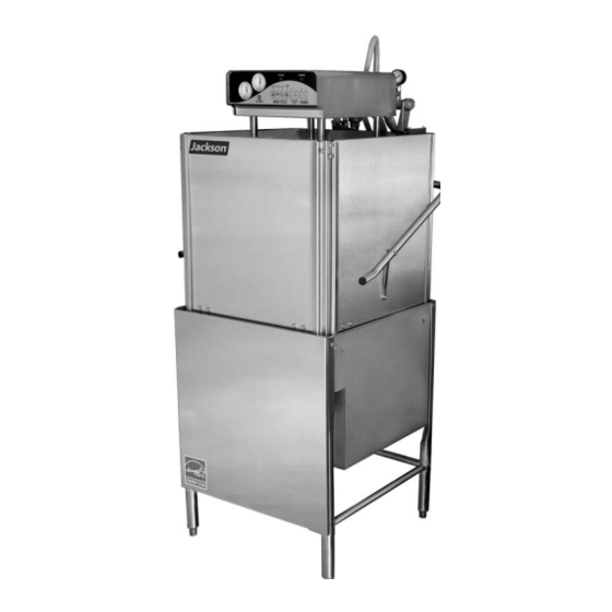
Tempstar series upright door
dishmachines
Hide thumbs
Also See for TEMPSTAR:
- Installation & operation manual (103 pages) ,
- Installation and quick manual (2 pages) ,
- Installation quick manual (2 pages)
Table of Contents
Advertisement
TEMPSTAR SERIES
UPRIGHT DOOR
DISHMACHINES
INSTALLATION, OPERATION,
AND SERVICE MANUAL
FOR JACKSON MODEL(S):
TEMPSTAR
TEMPSTAR LT
TEMPSTAR NB
TEMPSTAR
WITH VENTLESS
AND ENERGY RECOVERY
STEAM HEATED MODELS:
TEMPSTAR S
TEMPSTAR/LT/NB/ VENTLESS/S Technical Manual • Rev T • P/N 7610-003-61-42 • Issued: 11-11-2008 • Revised: 01-11-16
Advertisement
Table of Contents

Related Manuals for Jackson TEMPSTAR


Summary of Contents for Jackson TEMPSTAR
- Page 1 INSTALLATION, OPERATION, AND SERVICE MANUAL FOR JACKSON MODEL(S): TEMPSTAR TEMPSTAR LT TEMPSTAR NB TEMPSTAR WITH VENTLESS AND ENERGY RECOVERY STEAM HEATED MODELS: TEMPSTAR S TEMPSTAR/LT/NB/ VENTLESS/S Technical Manual • Rev T • P/N 7610-003-61-42 • Issued: 11-11-2008 • Revised: 01-11-16...
- Page 3 The labor to repair or replace such failed part will be paid by Jackson WWS, within the continental United States, Hawaii, and Canada, during the warranty period provided a Jackson WWS authorized service agency, or those having prior authorization from the factory, performs the service.
- Page 4 Updated schematic and control box assembly for rotary 01/10/13 8252 switch/Removed EnergyStar Logo. 03/07/13 QOF NDB-219 Updated Jackson logo and company name. Corrected part number for “right false panel kit,” pg. 43. 12/17/13 Removed “STOP” warning page, pg. 3. 05/28/14 8287 New bearing &...
- Page 5 Electrically-heated, low-temp, chemical sanitizing, no rinse booster; door-type dishmachine TEMPSTAR NB Electrically-heated, high-temp, hot-water sanitizing, no rinse booster; door-type dishmachine Jackson WWS, Inc. provides technical support for all of TEMPSTAR the dishmachines detailed with Ventless and Energy Recovery in this manual. We strongly...
-
Page 6: Table Of Contents
1/2” Solenoid Valve & 1/2” NPT Vacuum Breaker Repair Parts Kits ........56 Wash and Rinse Arm/Manifold Assemblies ................57 Tempstar Ventless System Assembly ..................59 Tempstar Ventless Door Interlock Assembly ................60 Door Interlock, Exhaust Fan, Transformer Box ................ 62 GO*BOX Components ......................63... - Page 7 Solid State 460V, 60 Hz, three phase ..................69 Tempstar (UT w/Cycle Switches) 460V, 60 Hz, three phase ........... 70 Solid State Tempstar LT & NB 208 - 230V, 50/60 Hz, single/three phase ....... 71 Tempstar LT & NB 208 - 230V, 50/60 Hz single/three phase ........... 72 Tempstar LT &...
-
Page 8: Specifications
Y-STRAINER MACHINE DIMENSIONS SPECIFICATIONS LEGEND A- WATER INLET (1/2” NPT) B- ELECTRICAL CONNECTION POINT C- DRAIN (1 1/2” NPT) D- STANDARD CLEARANCE BETWEEN MACHINE AND WALL (WITH DISH TABLE) IS 4” (10.2 cm) 07610-003-61-42-T... - Page 9 PRESSURE REGULATOR MACHINE DIMENSIONS SPECIFICATIONS LEGEND A- WATER INLET (1/2” NPT) B- ELECTRICAL CONNECTION POINT C- DRAIN (1 1/2” NPT) D- STANDARD CLEARANCE BETWEEN MACHINE AND WALL (WITH DISH TABLE) IS 4” (10.2 cm) 4 7/8” (12.4 cm) 25 1/4” (64.1 cm) 32”...
- Page 10 VENTLESS MACHINE DIMENSIONS SPECIFICATIONS LEGEND A- DRAIN (1 1/2" IPS) B- WATER INLET (3/4") MIP C- ELECTRICAL CONNECTIONS ALL VERTICAL DIMENSIONS ARE ± 1/2" DUE TO ADJUSTABLE BULLET FEET (134mm) (114mm) (642mm) (641mm) 32 (813mm) (134mm) 3 (79mm) 17 (432mm) (616mm) 82 (2083mm) 77 (1956mm)
-
Page 11: Table Dimensions
TABLE DIMENSIONS SPECIFICATIONS NOTE: Please remove the front dress panel from the dishmachine if mounting dishmachine for a corner installation and attaching side tables. Corner installation will trap panel making it diffi cult to remove. 4” (10.2 cm) MINIMUM TABLE DIMENSIONS CORNER INSTALLATION 20 1/2”... -
Page 12: Operating Capacities
1/2” Total Cycle Time Drain Line Size (NPT) 1 1/2” Minimum Chlorine Required (PPM) Tank Capacity (Gallons): Wash Tank TEMPSTAR NB/ TEMPSTAR S: Rinse Tank (TEMPSTAR) Wash Temperature (Minimum)(°F) Tank Capacity (Liters): Wash Temperature (Minimum)(°C) Wash Tank 30.3 Rinse Temperature (Minimum)(°F) Rinse Tank (TEMPSTAR) 11.4... -
Page 13: Electrical Requirements
Always verify with your electrical service contractor that your circuit protection is adequate and meets all applicable national and local codes. These numbers are provided in this manual simply for reference and may change without notice at any given time. TEMPSTAR Electrical Characteristics: RINSE HEATER TOTAL... - Page 14 ELECTRICAL REQUIREMENTS SPECIFICATIONS TEMPSTAR LT/TEMPSTAR NB Electrical Characteristics: RINSE HEATER TOTAL TYPICAL VOLTS PHASE RATINGS AMPS ELECTRICAL CIRCUIT 28 A 35 AMP 30 A 100 AMP 25 AMP 21 A 30 AMP 10 A 15 AMP 10 A 15 AMP...
-
Page 15: Installation Instructions
If such a situation occurs, do not return the unit to Jackson; instead, contact the carrier and ask them to send a representative to the site to inspect the damage to the unit and to complete an inspection report. - Page 16 Connection during the cycle. It is also recommended that a shock absorber (not supplied with the Tempstar model) be installed in the incoming water line. This prevents line hammer (hydraulic shock), induced by the solenoid valve as it operates, from causing damage to the equipment.
-
Page 17: Electrical Installation Instructions
INSTRUCTIONS INSTALLATION ELECTRICAL POWER Electrical and grounding connections must comply with the applicable portions of the National Electrical Code ANSI/NFPA 70 (latest edition) and/or other electrical codes. CONNECTIONS Disconnect electrical power supply and place a tag at the disconnect switch to indicate that you are working on the circuit. -
Page 18: False Panel Installation
FALSE PANEL INSTALLATION INSTALLATION Rack rail removed & repositioned for a corner operation. False panel positioned in unit. Insert this side fi rst. 07610-003-61-42-T... - Page 19 FALSE PANEL INSTALLATION INSTALLATION 1. Remove the rack assembly from the unit. 2. False panel will mount inside the dishmachine. 3. Position panel in unit on side to be closed. 4. Hold panel against side of dishmachine and push up. 5.
-
Page 20: Operating Instructions
FILLING THE Ensure that the delime switch is in the NORMAL position, and place the power switch into the ON position. The Tempstar should fi ll automatically and shut off when the WASH TUB appropriate level is reached (just below the pan strainer). Verify that the drain stopper is preventing the wash tub water from leaking excessively. - Page 21 OPERATING INSTRUCTIONS OPERATION WARM-UP CYCLES For a typical daily start-up, it may be necessary to run the machine through 3 cycles to ensure that all of the cold water is out of the system and to verify that the unit is operating correctly.
-
Page 22: Detergent Control
If the water cannot get hot enough, your results may not be satisfactory. This is why Jackson recommends that if you have installed the machine in an area with hard water, that you also install some type of water treatment equipment to help remove the dissolved solids from the water before it gets to the dishmachine. - Page 23 Certain dishmachine models require that chemicals be provided for proper operation and sanitization. Some models even require the installation of third-party chemical CONTROL feeders to introduce those chemicals to the machine. Jackson does not recommend or (CONTINUED) endorse any brand name of chemicals or chemical dispensing equipment. Contact your local chemical distributor for questions concerning these subjects.
-
Page 24: Delime Instructions
DELIME INSTRUCTIONS OPERATION To proceed with the delime operation, fi ll the dishmachine with the correct amount of DELIME delime solution as recommended by the chemical manufacturer. The tank capacities INSTRUCTIONS of the machine can be found in the Specifi cations section of this manual. After the chemicals are added, perform the following steps: 1. -
Page 25: Maintenance
However, this does not mean that some items will not wear MAINTENANCE out in time. Jackson highly recommends that any maintenance and repairs not specifi cally discussed in this manual should be performed by QUALIFIED SERVICE PERSONNEL ONLY. - Page 26 PREVENTATIVE MAINTENANCE MAINTENANCE PREVENTATIVE By following the operating and cleaning instructions in this manual, you should get the most effi cient results from your machine. As a reminder, here are some steps to take to MAINTENANCE ensure that you are using the dishmachine the way it was designed to work: (CONTINUED) 1.
-
Page 27: Troubleshooting
COMMON PROBLEMS TROUBLESHOOTING WARNING: Inspection, testing and repair of electrical equipment should only be performed by a qualifi ed service technician. Many of the tests require that the unit have power to it and live electrical components be exposed. USE EXTREME CAUTION WHEN TESTING THE MACHINE. PROBLEM POSSIBLE CAUSE REMEDY... - Page 28 COMMON PROBLEMS TROUBLESHOOTING WARNING: Inspection, testing and repair of electrical equipment should only be performed by a qualifi ed service technician. Many of the tests require that the unit have power to it and live electrical components be exposed. USE EXTREME CAUTION WHEN TESTING THE MACHINE. PROBLEM POSSIBLE CAUSE REMEDY...
-
Page 29: Top Mounted Control Box Assembly (Universal Timer)
TOP CONTROL BOX ASSEMBLY PARTS TOP CONTROL BOX ASSEMBLY WITH UNIVERSAL TIMER 07610-003-61-42-T... - Page 30 TOP CONTROL BOX ASSEMBLY PARTS (Continued) 21 21 07610-003-61-42-T...
- Page 31 TOP CONTROL BOX ASSEMBLY PARTS (Continued) 07610-003-61-42-T...
- Page 32 TOP CONTROL BOX ASSEMBLY PARTS (Continued) ITEM DESCRIPTION PART NUMBER Control Box Weldment 05700-003-30-14 Timer Bracket 05700-003-02-08 Lock Nut 6-32 05310-373-03-00 Heater Contactor 05945-109-01-69 Terminal Block 05940-011-48-27 Lock Nut 10-24 05310-373-01-00 Contactor,Wash Motor 05945-002-74-20 Relay 05945-111-47-51 Relay, (415V, 3PH, 5 Wire Only) 05945-111-89-75 Light, Green 05945-111-44-43...
- Page 33 TOP CONTROL BOX ASSEMBLY PARTS (Continued) ITEM DESCRIPTION PART NUMBER Decal,Ground 09905-011-86-86 Decal,L1, L2 09905-002-78-67 Bracket, Fuse Strip 05700-002-42-03 Fuse Holder, 6 pole 05920-002-42-13 Screw, 6-32 x 3/8” W/Ext Tooth Washer 05305-002-25-91 Decal, Dispenser Connection 09905-003-34-09 Timer, Universal 05945-003-33-09 Timer,Universal Fused(Alternate) 05945-003-75-23 Locknut, 10-32 05310-373-02-00...
-
Page 34: Hood Assembly (Bolted Single Support Design)
HOOD ASSEMBLY PARTS ITEM DESCRIPTION PART NUMBER Hood Weldment (Tempstar/Tempstar LT/Tempstar NB) 05700-002-29-79 Hood Support 05700-002-78-99 Bolt, 1/4”-20 x 1/2” Lon 05305-274-21-00 Washer, Flat, SS, 1/4”-20 ID 05311-174-01-00 Spacer, Sleeve Hood 05700-003-55-15 Locknut, 1/4”-20 with Nylon Insert (Not Shown) 05310-374-01-00... -
Page 35: Cantilever Arm/Door Assemblies
CANTILEVER ARM/DOOR ASSEMBLIES PARTS 11 12 07610-003-61-42-T... - Page 36 CANTILEVER ARM/DOOR ASSEMBLIES PARTS ITEM DESCRIPTION PART NUMBER Cantilever Arm 05700-031-50-67 Spring Pin, 1/4" x 1 1/8" 05315-407-06-00 Yoke Assembly 05700-000-75-77 Cotter Pin 05315-207-01-00 Yoke 05700-000-75-78 Clevis Pin, 5/16” x 1 3/8” 05315-700-01-00 Nylon Washer 05311-369-03-00 Bushing 03120-100-03-00 Locknut, 3/8”-16 S/S Hex Center 05310-256-04-00 Rod, Spring 05700-002-29-38...
- Page 37 Door Connecting Plate (Not Shown) 05700-002-20-78 Bracket, Cantilever Arm Support (Not Shown) 05700-031-88-00 Wear Button, 1/2" Dia. UHMW (Not Shown) 05700-011-88-01 Decal, Jackson LOGO (Not Shown) 09905-004-03-02 Door Interlock Bracket (Not Shown) 05700-004-23-14 Bracket, Cantilever Arm Support 09515-003-15-64 Wear Button, 1/2" Dia. UHMW...
-
Page 38: Tub Assembly
TUB ASSEMBLY PARTS SOLID STATE THERMOSTAT 36 33 31 30 Nut, 1/4”-20 Serrated Nut 05310-011-66-49 Bracket, Motor Support Weldment 05700-002-68-31 Pump Support Adjustable Bracket Complete Assembly 05700-002-20-46 Pump Support Adjustable Bracket 05700-002-20-41 07610-003-61-42-T... - Page 39 TUB ASSEMBLY PARTS ITEM DESCRIPTION PART NUMBER Tub Weldment 05700-002-12-59 Rack Assembly 05700-002-01-00 Bulk Head Plug 04730-609-05-00 See Page Entitled “Wash Motors” Gasket 05700-111-35-03 O-ring 05330-400-05-00 Bolt, Hex 3/8”-16 x 1 1/4" Long 05305-276-10-00 Lower Wash Manifold Weldment 05700-031-46-00 Suction Strain Weldment 05700-001-22-23 Suction Strain Bracket 05700-001-22-24...
- Page 40 TUB ASSEMBLY PARTS (Continued) ITEM DESCRIPTION PART NUMBER Lockwasher, 5/16", S/S, Split 05311-275-01-00 Nut, Hex, 5/16"-18, S/S 05310-275-01-00 Locknut, 10-24 with Nylon Insert 05310-373-01-00 Cover, Wash Heater 05700-031-47-57 Decal, Warning-Disconnect Power 09905-100-75-93 Decal, High Limit 09905-011-84-32 Thermostat Bracket 05700-011-81-64 Wash Heater Gasket 05330-011-47-79 Thermostat, Regulating 05930-510-02-79...
-
Page 41: Steam Tub Assembly
STEAM TUB ASSEMBLY PARTS SOLID STATE THERMOSTAT Nut, 1/4”-20 Serrated Nut 05310-011-66-49 Bracket, Motor Support Weldment 05700-002-68-31 Pump Support Adjustable Bracket Complete Assembly 05700-002-20-46 Pump Support Adjustable Bracket 05700-002-20-41 07610-003-61-42-T... - Page 42 STEAM TUB ASSEMBLY PARTS ITEM DESCRIPTION PART NUMBER Tub Weldment 05700-002-12-59 05700-002-01-00 Rack Assembly 04730-609-05-00 Bulk Head Plug See Page Entitled “Wash Motors” Gasket 05700-111-35-03 05330-400-05-00 O-ring 05305-276-10-00 Bolt, Hex 3/8”-16 x 1 1/4" Long 05700-031-46-00 Lower Wash Manifold Weldment 05700-001-22-23 Suction Strain Weldment 05700-001-22-24...
- Page 43 STEAM TUB ASSEMBLY PARTS (Continued) ITEM DESCRIPTION PART NUMBER Probe, High Water 06680-200-02-68 Thermostat, Regulating 05930-510-02-79 Kit, Wash Thermostat Replacement 06401-003-18-67 (Includes: thermostat, brass fi tting, 2 jumper wires & instructions) Cover, Wash Heater 05700-031-47-57 Decal, Warning-Disconnect Power 09905-100-75-93 Locknut, 10-24 with Nylon Insert 05310-373-01-00 Steam Coil 05700-031-41-37...
-
Page 44: Frame Assembly
FRAME ASSEMBLY PARTS ITEM DESCRIPTION PART NUMBER Bolt, 1/4”-20 x 1/2” 05305-274-02-00 Locknut, 1/4”-20 S/S Hex with Nylon Insert 05310-374-02-00 Front Panel 05700-002-36-65 Frame Weldment 05700-031-48-01 Bullet Foot 05340-108-01-03 Flanged Bullet Foot 05340-002-34-86 07610-003-61-42-T... -
Page 45: Rinse Tank Assembly
RINSE TANK ASSEMBLY PARTS See page entitled “WASH HEATERS/RINSE HEATERS”. ITEM DESCRIPTION PART NUMBER Booster Tank Weldment 05700-001-22-02 Locknut, 10-24 with Nylon Insert 05310-373-01-00 Washer, #10 S/S Flat 05311-173-01-00 Decal, Warning - Disconnect Power 09905-100-75-93 Booster Tank Cover Weldment 05700-001-29-30 Nut, Hex, 5/16"-18 05310-275-01-00 Locknut, 1/4"-20 with Nylon Insert... - Page 46 RINSE TANK & ROUND FLANGE HEATER ASSM PARTS See page entitled “WASH HEATERS/RINSE HEATERS”. ITEM DESCRIPTION PART NUMBER Booster Tank Weldment 05700-003-58-41 Locknut, 10-24 with Nylon Insert 05310-374-01-00 Washer, #10 S/S Flat 05311-174-01-00 Decal, Warning - Disconnect Power 09905-100-75-93 Booster Tank Cover Weldment 05700-001-29-30 Nut, Hex, 5/16"-18 05310-274-01-00...
-
Page 47: Coil Assembly
COIL ASSEMBLY PARTS ITEM DESCRIPTION PART NUMBER Complete Steam Coil Assembly 05700-002-08-62 Steam Coil Weldment 05700-021-41-38 Stand C, Steam Coil Support 05700-002-08-52 Stand D, Steam Coil Support 05700-002-08-53 Gasket, Steam Coil 05700-001-17-86 Washer, Steam Coil 05700-001-17-87 Adapter, Steam Coil Nut 05310-011-17-85 Stand A, Steam Coil Support 05700-002-08-50... -
Page 48: Incoming Steam Plumbing Assembly
INCOMING STEAM PLUMBING ASSEMBLIES PARTS ITEM DESCRIPTION PART NUMBER Complete Assembly 05700-002-01-55 Union, 3/4’’ NPT, Black Iron 04730-912-01-00 Bushing, Reducing, 3/4’’ to 1/2’’ 04730-911-02-34 Elbow, 3/4” 90° Street 04730-011-87-37 Nipple, Close, 3/4’’ NPT, Black Iron 04730-907-01-00 Steam Trap, 3/4” NPT F&T 06680-500-02-77 07610-003-61-42-T... - Page 49 INCOMING STEAM PLUMBING ASSEMBLIES PARTS ITEM DESCRIPTION PART NUMBER Complete Assembly 05700-002-01-60 Bushing, Reducing, 3/4’’ to 1/2’’ 04730-911-02-34 Union, 3/4’’ NPT, Black Iron 04730-912-01-01 Elbow, 90B 3/4” NPT Black Iron 04730-906-10-34 Nipple, Close, 3/4’’ NPT, Black Iron 04730-907-01-00 Gate Valve, 3/4” NPT 04820-100-19-00 Y-Strainer, 3/4”...
-
Page 50: Wash Motors
WASH MOTORS PARTS The Tempstar models covered in this manual come supplied with various wash motor assemblies (a wash motor assembly includes the wash motor and the pump end), depending on the characteristics of the machine. To ensure that you order... -
Page 51: Motor & Pump Assembly
MOTOR & PUMP ASSEMBLY PARTS Pump Only Assembly, 50HZ Complete Pump & Motor Assembly, 50HZ (Area indicated within box, Casing is 06105-002-19-87 included) 05700-002-85-38 Complete Pump & Motor Assembly, 60HZ 06105-002-69-78 Pump Only Assembly, 60HZ (Area indicated within box, Casing is included) 05700-002-79-51 Pump Casing (Not shown), 50HZ... -
Page 52: Wash Heaters/Rinse Heaters
04540-002-77-24 Tempstar 04540-121-65-99 04540-100-01-15 04540-121-63-39 Tempstar 04540-121-65-99 04540-100-01-15 04540-121-63-39 Model Volts PHASE Wash Heater Tempstar LT 04540-121-47-39 HEATER CONVERSION KITS Tempstar LT 04540-121-47-39 Tempstar LT 04540-121-47-39 1 to 3 Phase, 208-230V/50hz Tempstar LT 04540-121-47-39 Conversion Kit: 06401-003-15-59 Tempstar LT 04540-121-47-39... - Page 53 ROUND FLANGED RINSE HEATER PARTS Model Volts PHASE Wash Heater Rinse Heater (12 KW) Rinse Heater (14 KW) Tempstar 04540-003-58-27 04540-003-58-28 Tempstar 04540-003-58-27 04540-003-58-28 Tempstar 04540-003-58-27 04540-003-58-28 Tempstar 04540-003-58-27 04540-003-58-28 Tempstar 04540-003-58-27 04540-003-58-28 Tempstar 04540-003-58-27 04540-003-58-28 Tempstar 04540-003-58-27 04540-003-58-28 Tempstar...
-
Page 54: Incoming/Outlet Plumbing Assembly
INCOMING/OUTLET PLUMBING ASSEMBLY PARTS Y - STRAINER OPTION TEMPSTAR Incoming Plumbing TEMPSTAR Outlet Plumbing (Complete Assembly) (Complete assembly) 05700-003-60-74 05700-003-60-75 Tube Length Chart Item # Length (inches) 1/2” x 2 1/2” Long 1/2” x 37” Long 1/2” x 3” Long 1/2”... - Page 55 INCOMING/OUTLET PLUMBING ASSEMBLY PARTS ITEM DESCRIPTION PART NUMBER Fitting, Tee, 1/2” x 1/2” x 1/4” 04730-411-25-01 Adapter, 1/2” MNPT x CU Male 04730-011-59-53 Strainer, Y 1/2” 04730-217-01-10 Vave, Ball Test Cock 1/4” Bronze 04810-011-72-67 Adapter, 1/2” 04730-401-03-01 Union, 1/2” 04730-412-05-01 Bushing, HEX 3/4 MNPT-1/2 FNPT Brass 04730-002-56-27 F-Tube, Copper 1/2”...
- Page 56 INLET PLUMBING PARTS Y - STRAINER OPTION TEMPSTAR LT & TEMPSTAR NB INCOMING PLUMBING ASSEMBLY ITEM DESCRIPTION PART NUMBER Complete Assembly 05700-003-60-73 Tee, Brass, 1/2" x 1/2" x 1/4" NPT 04730-411-25-01 Adapter, 1/2” MNPT x Cu Male 04730-011-59-53 Strainer, Y 1/2”...
- Page 57 INCOMING/OUTLET PLUMBING ASSEMBLY PARTS PRESSURE REGULATOR OPTION 07610-003-61-42-T...
- Page 58 When servicing plumbing components, take care not to damage the threads of each individual item. Damaged threads can cause leaks and loss of pressure, which could adversely effect the performance of the Tempstar dishmachine. It is strongly recommended that tefl on thread tape, used in conservative amounts, be applied to threads when joining components together.
- Page 59 INLET PLUMBING - PRESSURE REGULATOR PARTS ITEM DESCRIPTION PART NUMBER Tee, Brass, 1/2" x 1/2" x 1/4" NPT 04730-411-25-01 Adapter, 1/2” MNPT x Cu Male 04730-011-59-53 Water Pressure Regulator, 1/2" NPT 04820-100-04-07 Valve, Ball, Bronze, 1/4" NPT 04810-011-72-67 Adapter, 1/2” Male/Cu to MSPS 04730-401-03-01 Pressure Gauge, 0-100 PSI 06685-111-59-66...
-
Page 60: Tempstar - Ventless Plumbing
TEMPSTAR - VENTLESS PLUMBING PARTS RINSE INJECTOR 09515-004-22-73 HOSE PAC, ASSEMBLY (TEMPSTAR) 05700-004-20-01 HOSE PAC, ASSEMBLY (TEMPSTAR HH) 05700-004-20-02 ITEM DESCRIPTION PART NUMBER Vac Breaker 1/2 Brass 04820-003-06-13 Elbow, 90 Degree 1/2 Street Brass 04730-206-08-00 W-Plumbing, Rinse Injector 05700-004-19-83 A-Plumbing, Outlet w/ Heat Exc. - Page 61 TEMPSTAR - VENTLESS PLUMBING PARTS ITEM DESCRIPTION PART NUMBER Bushing, Hex 3/4"M to 1/2" Brass 04730-002-56-27 Nipple, Brass 1/2" X 3" NPT 04730-004-20-10 Elbow, 1/2 NPT 90 Brass 04730-011-42-96 Tee, 1/2 FNPT X 1/2 FNPT 1/4 FNPT 04730-002-22-56 Union, 1/2" X 1/2" Brass...
- Page 62 TEMPSTAR - VENTLESS PLUMBING PARTS ITEM DESCRIPTION PART NUMBER Bushing, Hex 3/4"M to 1/2" Brass 04730-002-56-27 Elbow, 3/4 Street Brass 90 Degress 04730-206-04-34 Regulator, Pressure 3/4 06685-011-58-22 Nipple, 3/4 NPT X 1-3/8 Closed Brass 04730-207-34-00 Valve, 3/4" - 220V Solenoid...
-
Page 63: 1/2" Solenoid Valve & 1/2" Npt Vacuum Breaker Repair Parts Kits
SOLENOID VALVE & VACUUM BREAKER PARTS 1/2” SOLENOID VALVE & 1/2” NPT VACUUM BREAKER REPAIR PARTS KITS 4810-200-03-18 Complete Vacuum Breaker Assembly, 1/2” NPT 04820-003-06-13 Complete 110 Volt Solenoid Valve Assembly, 1/2” 04810-100-12-18 Coil & Housing only 06401-003-07-43 Complete 240 Volt Solenoid Valve Assembly, 1/2” 04810-100-09-18 Coil &... -
Page 64: Wash And Rinse Arm/Manifold Assemblies
WASH & RINSE ARM/MANIFOLD ASSEMBLIES PARTS DETAIL “A” FINAL RINSE ARMS & MANIFOLD Rinse Injector Weldment 1 per machine 05700-002-56-75 Plug, 1/8” NPT, Brass 3 per Rinse Injector 04730-209-07-37 Rinse Injector Gasket DETAIL “B” 2 per machine WASH ARMS & MANIFOLD 05330-111-42-81 07610-003-61-42-T... - Page 65 WASH & RINSE ARM/MANIFOLD ASSEMBLIES PARTS (Continued) EXPLODED VIEW OF ITEM 17 1 or 16 ITEM DESCRIPTION PART NUMBER Upper Manifold 05700-031-34-82 Nut, 3/8"-16 S/S Hex 05310-276-01-00 Lockwasher,3/8 05311-276-01-00 Bolt, Hex 3/8”-16 x 7/8" Long 05306-011-36-95 O Ring 05330-111-35-15 Positioning Bracket, Manifold Tube 05700-011-34-63 Tube, Wash Manifold 05700-131-15-07...
-
Page 66: Tempstar Ventless System Assembly
TEMPSTAR VENTLESS SYSTEM ASSEMBLY PARTS 07610-003-61-42-T... -
Page 67: Tempstar Ventless Door Interlock Assembly
TEMPSTAR VENTLESS SYSTEM ASSEMBLY PARTS (Continued) ITEM DESCRIPTION PART NUMBER Coil, Heat Exchanger 04420-004-19-61 Inlet, Cold Water 05700-004-19-01 Ring, Water Inlet 05700-004-19-24 Plate, Fan Mounting 05700-004-18-07 Upper Shroud 05700-004-18-06 Exhaust Box 05700-004-18-04 Gasket, Heat Exchanger 05330-004-18-22 Gauge 06680-011-86-42 Coil Box Back... - Page 68 TEMPSTAR VENTLESS DOOR INTERLOCK PARTS ITEM DESCRIPTION PART NUMBER Door Interlock Assembly 05700-004-23-06 Guide Block, Door Lock 09330-004-22-72 F-Cover, Door Lock Mounting 05700-004-22-80 W-Rod, Interlock Weldment 05700-004-23-15 Soleniod, Horizontal 1" Push 04820-004-24-11 Spring, Comp. 05935-004-24-10 W-Base, Door Interlock Box 05700-004-24-25...
-
Page 69: Door Interlock, Exhaust Fan, Transformer Box
DOOR INTERLOCK, EXHAUST FAN, TRANSFORMER BOX PARTS DOOR INTERLOCK (SDI) /EXHAUST FAN CONTROL/TRANSFORMER MOUNTING BOX Door Interlock Box Bottom Door Interlock Box Cover 05700-001-21-26 05700-001-21-27 OTHER DOOR INTERLOCK (SDI) COMPONENTS (NOT SHOWN): DESCRIPTION PART NUMBER Pipe Clamp (found on the side of the machine) 05700-000-35-05 Solenoid, Electrical Interlock Option 04810-100-61-33... -
Page 70: Go*Box Components
GO*BOX COMPONENTS PARTS A GO*BOX is a kit of the most needed parts for a particular model or model family to successfully effect a repair in the fi rst call 90% or more of the time. The following components may be ordered together using the following Mfg. No.: 06401-003-62-04 ITEM DESCRIPTION PART NUMBER... -
Page 71: Drain Quench Assembly
DRAIN QUENCH ASSEMBLY PARTS ITEM DESCRIPTION PART NUMBER Nipple, 1/4 NPT x 3 Brass 04730-004-08-07 Nipple, 1/4 NPT x 3 Brass 04730-004-08-07 Reducer, 1-1/2 x 1/2 Hex Brass 04730-002-55-75 Nipple, 1-1/12 Brass Close 04730-207-40-00 Tee, 1-1/2 Brass 04730-011-69-93 Reducer, 1-1/2 x 1/4 Hex Brass 04730-002-55-76 Union,1/4 Modifi... - Page 72 DRAIN QUENCH ASSEMBLY PARTS (Continued) ITEM DESCRIPTION PART NUMBER Wash Heater Cover 05700-004-07-92 Liquid Tight Fitting (Large) 05975-011-65-51 Conduit Fitting, 45°-1/2" 05975-011-45-23 Lock Nut, 6-32 Hex 05310-373-03-00 Thermostat 05930-003-13-65 Conduit Fitting, 90°-1/2" 05975-011-45-14 Liquid Tight Fitting (Small) 05975-011-49-03 07610-003-61-42-T...
- Page 73 DRAIN QUENCH ASSEMBLY PARTS (Continued) Connect 1 1/2” drain plumbing Connect 1/4” cold water line (elbow can be removed if not needed) 07610-003-61-42-T...
-
Page 74: Solid State 208 - 230V, 50/60 Hz, Single/Three Phase
SOLID STATE 208-230V, 50/60 HZ, 1 & 3 PHASE SCHEMATICS TEMPSTAR (TOP MOUNT W/ CYCLE SWITCHES) 07610-003-61-42-T... -
Page 75: Tempstar (Ut W/Cycle Switches) 208 - 230V, 50/60 Hz, Single/Three Phase
TEMPSTAR 208-230V, 50/60 HZ, 1 & 3 PHASE SCHEMATICS TEMPSTAR (TOP MOUNT W/ CYCLE SWITCHES) 07610-003-61-42-T... -
Page 76: Solid State 460V, 60 Hz, Three Phase
SOLID STATE 460 V, 60 HZ, 3 PHASE SCHEMATICS TEMPSTAR (TOP MOUNT W/ CYCLE SWITCHES) 07610-003-61-42-T... -
Page 77: Tempstar (Ut W/Cycle Switches) 460V, 60 Hz, Three Phase
TEMPSTAR 460 V, 60 HZ, 3 PHASE SCHEMATICS TEMPSTAR (TOP MOUNT W/ CYCLE SWITCHES) -
Page 78: Solid State Tempstar Lt & Nb 208 - 230V, 50/60 Hz, Single/Three Phase
SOLID STATE LT & NB 208-230V, 50/60HZ,1 & 3 PHASE SCHEMATICS TEMPSTAR (TOP MOUNT W/ CYCLE SWITCHES) 07610-003-61-42-T... -
Page 79: Tempstar Lt & Nb 208 - 230V, 50/60 Hz Single/Three Phase
TEMPSTAR LT & NB 208-230V, 50/60HZ, 1 & 3 PHASE SCHEMATICS TEMPSTAR (TOP MOUNT W/ CYCLE SWITCHES) -
Page 80: Tempstar Lt & Nb (Ut W/Cycle Switches) 460V, 60 Hz, Three Phase
TEMPSTAR NB & LT 460V, 50/60 HZ, 3 PHASE SCHEMATICS TOP MOUNT UNIVERSAL TIMER 07610-003-61-42-T... -
Page 81: Tempstar S (Universal Timer) 208 - 230V, 60 Hz, Single/Three Phase
TEMPSTAR S 208-230V, 50/60 HZ, 1 & 3 PHASE SCHEMATICS TOP MOUNT UNIVERSAL TIMER TEMPSTAR STEAM TEMPSTAR STEAM ELCTRICAL DIAGRAM ELCTRICAL DIAGRAM 208/230 VOLT 50/60 Hz 1/3 PHASE 208/230 VOLT 50/60 Hz 1/3 PHASE 07610-003-61-42-T... -
Page 82: Schematics
SDI OPTIONS SCHEMATICS 07610-003-61-42-T... -
Page 83: Drain Quench Options
DRAIN QUENCH OPTIONS SCHEMATICS 07610-003-61-42-T... -
Page 84: Addendum
(606) 523-9795 09905-003-69-11D Tempstar units that are manufactured with the above referenced data plate are able to be fi eld- converted to different phases and voltages. To accomplish this, your unit should have shipped with the Tempstar Phase Conversion Kit, part number 06401-003-71-71. This kit contains the appropriate decals and schematics to apply to your unit once the conversion is complete. - Page 86 Jackson WWS, Inc. • 6209 N. US Hwy 25E • Gray, KY 40734 USA 1.888.800.5672 • www.jacksonwws.com TEMPSTAR/LT/NB/ VENTLESS/S Technical Manual • Rev T • P/N 7610-003-61-42 • Issued: 11-11-08 • Revised: 01-11-16...
Need help?
Do you have a question about the TEMPSTAR and is the answer not in the manual?
Questions and answers