Table of Contents
Advertisement
Quick Links
Certified for
Canada and U.S.A
Outdoor Gas Barbeque Owner's Manual
This manual is for use with 700, 700BI and 850BI series grills
Warning:
Please read and understand the contents of this manual fully before operating. Failure to
do so may result in fire or explosion. Homeowners should retain these instructions.
All barbecues and carts are designed for OUTDOOR use only and cannot be installed in or on boats.
This barbecue is CANNOT be installed in or on Recreational Vehicles. Not for commercial use.
Manufactured by:
Jackson Grills Inc.
2945 Jacob Road
Duncan, B.C. V9L 6W4
Email: jacksongrills@shaw.ca
Phone: 1-250-715-0820
Fax:
1-250-715-0821
Advertisement
Table of Contents

Subscribe to Our Youtube Channel
Related Manuals for Jackson Grills 700 Series


Summary of Contents for Jackson Grills 700 Series
- Page 1 All barbecues and carts are designed for OUTDOOR use only and cannot be installed in or on boats. This barbecue is CANNOT be installed in or on Recreational Vehicles. Not for commercial use. Manufactured by: Jackson Grills Inc. 2945 Jacob Road Duncan, B.C. V9L 6W4 Email: jacksongrills@shaw.ca...
-
Page 2: Table Of Contents
TABLE OF CONTENTS: SAFETY. LP GAS CYLINDER REPLACEMENT. OPD EQUIPPED CYLINDER. HOSE AND REGULATOR. LEAK TESTING. INSTALLATION. CLEARANCES. ASSEMBLY. GETTING TO KNOW YOUR GRILL LIGHTING INSTRUCTIONS. GAS CONVERSION. MAINTENANCE. GRILLING TIPS AND TECHNIQUES. TROUBLE SHOOTING. PARTS LIST. EXPLODED VIEWS. WARRANTY. A MESSAGE TO OUR CUSTOMERS. -
Page 3: Safety
SAFETY: Your new Jackson Grill barbeque is a safe, convenient appliance when used and maintained properly. As with all gas-fired appliances, certain safety precautions must be observed. precautions may result in damage or injury. assembly or operation of this appliance, you should contact your dealer, gas appliance technician or your gas company. -
Page 4: Specifications
300 degrees F. When activated, a flow-limiting device will limit the flow of gas to 10 cubic feet per hour. The LP Gas Cylinder is not included with the Gas Grill. Be sure to purchase one with the QCC valve. The external threads the inlet port of the valve recognize this valve. -
Page 5: Operation
4. Keep out of reach of small children. 5. When the LP gas cylinder is connected to the gas grill, the LP gas cylinder must be stored outside in a well-ventilated area. 6. Keep the ventilation openings for the LP cylinder enclosure free and clear of debris. -
Page 6: Opd Equipped Cylinder
OPD EQUIPPED CYLINDER: Effective January 1, 1998, the standard for outdoor gas appliances, ANSI Z21.58/CAN CGA-1.6, requires that appliances are to be used with cylinders equipped with an Overfill Prevention Device (OPD). The OPD is designed to reduce the potential for the overfilling of propane cylinders, thus reducing the possibility of relief valve discharges of raw propane. -
Page 7: Leak Testing
4. Leak test the connection. See “leak test”. 5. Refer to lighting instructions. To avoid activating the Flow Limiting Device when lighting, open the cylinder valve slowly with the appliance valves off. If the Flow Limiting Device is accidentally activated, turn off cylinder valve and appliance valves, wait 10 seconds to allow the device to reset, open cylinder valve slowly, then open the appliance valve. -
Page 8: Installation
INSTALLATION: In Canada, this appliance must be installed in accordance with the local code and relevant CGA standards: CAN/CGA-B149.1 LP Gas/Propane Installation Code and latest codes where applicable. In the USA, this appliance must be installed in accordance with the local code and relevant national code: ANSI Z223.1 –... -
Page 9: Clearances
Ensure that the constructed island is well secured and that this island is level in all directions. Place the grill into the cut out located in the island. Connect the gas line to the gas grill located on the left hand side of this grill. -
Page 10: Assembly
If damage is present please contact you local dealer for replacement components. Please replace all damaged components with original manufacturer’s parts only no substitutions will be permitted. Please remove all packaging from all components of the gas grill before operating. TOLLS REQUIRED FOR ASSEMBLY:... - Page 11 After the Side Shelves have been installed, ensure the Grill Head is pushed back in the pedestal as far as possible. With the screws removed from the securing straps, place a screw through the side of the Condiment bins and secure the Condiment Bins to the Display Panel.
- Page 12 Rotisserie Kit Completed Installation Rotisserie Rod Bushing Placed on the cut out provided on the Inner Hood Upper Flavor Shield, Cooking Grid Installation. Remove the Upper Flavor Shields form the Packaging. Please ensure that all protective plastic has been removed from these parts. These Upper Flavor shields should be placed on the pins provided on the Firebox Front and Rear.
-
Page 13: Assembly
Main Gas Line Connections for Propane Gas and Natural Gas. The main Fuel supply gas line is connected to a Manifold Tee securely mounted inside the pedestal located on the left hand side of the pedestal. Remove the Propane hose and regulator assembly from the packaging. Please ensure that there is no debris inside the brass flare connection or inside the rubber hose. -
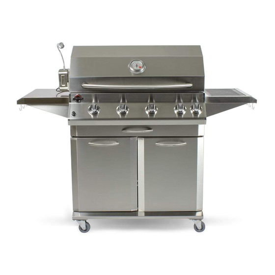
Page 14: Getting To Know Your Grill
Getting To Know Your Grill. Outer Hood Handle Hood Thermometer Outer Hood Cooking Grids Side Shelf Condiment Bins X 2 Pedestal Pedestal Doors X 2 Propane Tank Slide out Pedestal Gas manifold Pull Out Grease Tray Main Control Knobs / Display Panel Electronic Ignition Side Burner Side Shelf Warming Rack... -
Page 15: Lighting Instructions
MAIN BURNER LIGHTING To light the Main Burners always start with the Left Hand Burner first. Turn the Left hand Control Knob to HI and Depress the Igniter Button. Once this burner has lit, simply turn the next Control Knob to the right to high and this burner will light, repeat this step for the remaining burners. -
Page 16: Gas Conversion
Operating The Rear Burner When operating the Rear Burner please ensure that the Warming Rack is REMOVED. The Warming Rack will become damaged if NOT removed while the Rear Infrared Burner is in use. The rear burner is specially designed to be used with the Rotisserie Kit, and should ONLY be used when using the Rotisserie Kit. -
Page 17: Rear Burner
Using a 13 mm wrench undo all of the main burner orifices from the underside of the Display Panel. Place then aside form any other orifices included in the Natural Gas Conversion Kit. Using an approved thread sealant, replace the Main Burner Orifices with the NEW Natural Gas orifices supplied. -
Page 18: Gas Conversion
SIDE BURNER Open the side burner lid and remove the grate over the burner head. Undo the 2 Phillips head screws that hold the Flame Thrower (burner ignition) and VERY Carefully move away from the burner Head. Undo the 3 screws that hold the Burner Head onto the Side Shelf base. -
Page 19: Maintenance
GAS LINE Remove the 3/8” flare fitting that attaches the propane hose from the Manifold block inside of the pedestal and replace with an approved 10’ Natural Gas Hose neoprene hose. Part # NGHOSE REMEMBER TO LEAK CHECK ALL FITTINGS AND ORIFICES AFTER ALL OF THE CONVERSION IS COMPLETED, LEAK CHECK ALL FITTINGS AND TEST FIRE ALL... -
Page 20: Rotisserie Cooking
FOOD SAFETY TIPS AND TECHNIQUES We want to enjoy healthy and safe grill cooking, so here are some tips for basic barbecue hygiene: Bacteria are living organisms that grow and multiply rapidly in warm moist foods. Marinate meat in the refrigerator and take it out one half hour before grilling, if you want to grill your prepared meat at room temperature. -
Page 21: Trouble Shooting
Improper gap at electrode tip. Normal occurrence on hot days. SOLUTION Ensure lighting procedure followed carefully. All gas grill valves must be in the off position when the tank valve is turned on. Turn tank on for all pressure to equalize. lighting instructions. -
Page 22: Parts List
- PARTS LIST Part Number Part Description 1 07-400 Outer Hood 2 04-3403 Warming Rack Bracket 3 07-402 Hood Handle 4 07-4505 Thermometer 5 07-403 Inner Hood 6 07-404 Rear Burner Mount 7 07-4508 Inner Hood Back Cover 8 07-405 Warming Rack 9 04-34510 Collector Box 10 07-4506 Upper Flavor Shields... -
Page 23: Exploded Views
EXPLODED VIEW... -
Page 24: Warranty
Jackson Grills Inc. or its parties will not be responsible for the installation, labor or any other costs or expenses related to the re installation of the warranted part, and such expenses are not covered by this warranty. - Page 25 Please take the time to read the whole manual and familiarize yourself with all of the features of the Jackson Grill. This manual also contains important safety information and operation instructions.
Need help?
Do you have a question about the 700 Series and is the answer not in the manual?
Questions and answers