Table of Contents
Advertisement
Quick Links
Download this manual
See also:
Instruction Manual
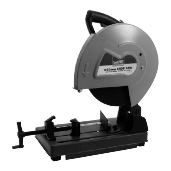
350mm CHOP SAW
STOCK No.55809
PART No.CS14A
(110V)
52623 (
230V)
• INSTRUCTIONS •
IMPORTANT: PLEASE READ THESE INSTRUCTIONS CAREFULLY TO ENSURE THE
SAFE AND EFFECTIVE USE OF THIS TOOL.
04/2001
GENERAL INFORMATION
This manual has been compiled by Draper Tools and is an integrated part of the power tool equipment, which
should be kept with the machine.
This manual describes the purpose for which this tool has been designed and contains all the necessary
information to ensure its correct and safe use.We recommend that this manual is read before any operation of
the machine, before performing any kind of adjustment to the machine, and prior to any maintenance tasks. By
following all the general safety instructions contained in this manual, it will ensure both machine and operator
safety, together with longer life of the tool itself.
All photographs and drawings in this manual are supplied by Draper Tools to help illustrate the operation of the
machine.
Whilst every effort has been made to ensure accuracy of information contained in this manual, the Draper Tool
policy of continuous improvement determines the right to make modifications without prior warning.
Advertisement
Table of Contents

Subscribe to Our Youtube Channel
Summary of Contents for Draper CS14A
-
Page 1: General Information
04/2001 GENERAL INFORMATION This manual has been compiled by Draper Tools and is an integrated part of the power tool equipment, which should be kept with the machine. This manual describes the purpose for which this tool has been designed and contains all the necessary information to ensure its correct and safe use.We recommend that this manual is read before any operation of... -
Page 2: Table Of Contents
Operation & Use ..................7 - 8 Maintenance, Accessories & Wiring Diagram...........9 Troubleshooting .....................10 DECLARATION OF CONFORMITY Draper Tools Ltd. Hursley Road, Chandler’s Ford, Eastleigh, Hampshire. SO53 1YF. England. Declare under our sole responsibility that the product: Stock Nos:- 55809 & 52623. -
Page 3: Specification/Guarantee
This guarantee applies in lieu of any other guarantee expressed or implied and variations of its terms are not authorised. Your Draper guarantee is not effective unless you can produce upon request a dated receipt or invoice to verify your proof of purchase within the 12 month period. -
Page 4: Power Supply
(i.e. red). Fuse covers are available from your Draper Tools stockist. If the fitted plug is not suitable, it should be cut off and destroyed. *The end of the cable should now be suitably prepared and the correct type of plug fitted. -
Page 5: General Safety Instructions
IMPORTANT Draper Tools Limited recommends that this machine should not be modified or used for any application other than that for which it was designed. If you are unsure of its relative applications do not hesitate to contact us in writing and we will advise you. -
Page 6: Safety Rules For Chop Saw
SAFETY RULES FOR CHOP SAWS MAKE SURE abrasive wheel is not contacting WARNING: Do not operate your abrasive workpiece before switch is turned on. cut-off saw until it is completely assembled and installed according to the instructions. ALLOW the motor to come up to full speed IF YOU ARE NOT thoroughly familiar with the before starting cut. -
Page 7: Getting To Know Your Chop Saw
GETTING TO KNOW YOUR CHOP SAW Fig. 1 ✕✌ ✖✌ ✕✙✌ ✗✌ ✜✌ ✘✌ ✙✌ ✢✌ ✕✗✌ ✕✔✌ ✕✖✌ ✕✛✌ ✕✚✌ ✚✌ ✛✌ ✕✘✌ ✕✕✌ Fig. 1 1. Trigger locking button 10. Depth stop 2. Trigger 11. Lock nut 3. Transportation handle 12. -
Page 8: Operation & Use
Fig.2. NOTE: We suggest that when the machine is not in use. The trigger be locked in the off position using a padlock ✭✌ (not supplied) (Draper Tools recommend Stock No. 60177). 3. ADJUSTING CUTTING DEPTH (Fig 4) Fig. 4 For deeper cuts screw the adjusting screw ✮✌... - Page 9 OPERATION & USE 5 ANGLE CUTING GUIDE (Fig.6) Fig. 6 Loosen screw ✳✌ with the hexagon wrench provided. Adjust fence ✴✌ to the required angle and then secure with screw ✳✌. The backstop can ✳✌ ✴✌ be adjusted backwards and forwards to meet your requirements.
-
Page 10: Maintenance, Accessories & Wiring Diagram
MAINTENANCE FTER EACH USE: Disconnect the plug from the power supply. Remove the disc and flanges. Wipe deposits of dust from the housing and guard. Check operation and condition of the lower guard, it should be securely attached and working properly. The cable and tool should be wiped occasionally with a clean cloth and mild soap only to prevent deterioration from oil and grease. -
Page 11: Troubleshooting
TROUBLESHOOTING WARNING: FOR YOUR OWN SAFETY ALWAYS TURN THE MAIN SWITCH ON THE MACHINE ‘OFF’ AND REMOVE THE PLUG FROM THE POWER SUPPLY BEFORE CARRING OUT ANY MAINTENANCE OR TROUBLESHOOTING. Motor Trouble Probable Cause Remedy Motor does not 1. Fuse. 1. - Page 12 ©Published by Draper Tools Ltd. No part of this publication may be reproduced, stored in a retrieval system or transmitted in any form or by any means, electronic, mechanical photocopying, recording or otherwise without prior permission in writing from Draper Tools Ltd.


Need help?
Do you have a question about the CS14A and is the answer not in the manual?
Questions and answers