Table of Contents
Advertisement
Quick Links
INSTRUCTIONS FOR
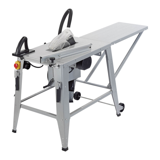
315mm 2000W 230V
Contractors Saw
Stock No.84708
Part No.CTS315A
IMPORTANT: PLEASE READ THESE INSTRUCTIONS CAREFULLY TO ENSURE THE SAFE AND
EFFECTIVE USE OF THIS PRODUCT.
GENERAL INFORMATION
These instructions accompanying the product are the original instructions. This document is part of the product, keep it
for the life of the product passing it on to any subsequent holder of the product. Read all these instructions before
assembling, operating or maintaining this product.
This manual has been compiled by Draper Tools describing the purpose for which the product has been designed, and
contains all the necessary information to ensure its correct and safe use. By following all the general safety instructions
contained in this manual, it will ensure both product and operator safety, together with longer life of the product itself.
AlI photographs and drawings in this manual are supplied by Draper Tools to help illustrate the operation of the product.
Whilst every effort has been made to ensure the accuracy of information contained in this manual, the Draper Tools policy
of continuous improvement determines the right to make modifications without prior warning.
Advertisement
Table of Contents

Subscribe to Our Youtube Channel
Related Manuals for Draper CTS315A


Summary of Contents for Draper CTS315A
-
Page 1: General Information
AlI photographs and drawings in this manual are supplied by Draper Tools to help illustrate the operation of the product. -
Page 2: Title Page
Commercial copying, redistribution, hiring or lending is prohibited. No part of this publication may be stored in a retrieval system or transmitted in any other form or means without written permission from Draper Tools Limited. In all cases this copyright notice must remain intact. -
Page 3: Table Of Contents
CONTENTS 2.1 CONTENTS Page content Page TITLE PAGE INTRODUCTION ........................2 REVISION HISTORY........................2 UNDERSTANDING THIS MANUAL ....................2 COPYRIGHT NOTICE ........................2 CONTENTS CONTENTS ..........................3 GUARANTEE GUARANTEE ..........................4 INTRODUCTION SCOPE ............................5 SPECIFICATION ..........................5 HANDLING & STORAGE ......................5 HEALTH & SAFETY INFORMATION GENERAL SAFETY INSTRUCTIONS FOR POWER TOOL USE ..........6-7 SPECIFIC SAFETY INSTRUCTIONS FOR TABLE SAWS ............ -
Page 4: Guarantee
This guarantee applies in lieu of any other guarantee expressed or implied and variations of its terms are not authorised. Your Draper guarantee is not effective unless you can produce upon request a dated receipt or invoice to verify your proof of purchase within the guarantee period. -
Page 5: Introduction
The table saw described in this manual is designed to cut wood and wood derived materials. The work piece is manually fed on to the saw blade. Any other application is considered misuse. 4.2 SPECIFICATION Stock nos..........................84708 Part nos..........................CTS315A Motor: Rated voltage .......................... 230V Rated frequency ......................50Hz Rated input .......................2000W Revolutions per minute (no load) ...............2950r/min... -
Page 6: Health & Safety Information
HEALTH & SAFETY INFORMATION 5.1 GENERAL SAFETY INSTRUCTIONS FOR POWER TOOL USE When using any type of power tool there are steps that should be taken to make sure that you, as the user, remain safe. Common sense and a respect for the tool will help reduce the risk of injury. Read the instruction manual fully. -
Page 7: Specific Safety Instructions For Table Saws
HEALTH & SAFETY INFORMATION Wait for the machine to stop. Unless the machine is fitted with a safety brake; some parts may continue to move due to momentum. Wait for all parts to stop; then unplug it from the power supply before making any adjustments, carrying out maintenance operations or just finishing using the tool. - Page 8 HEALTH & SAFETY INFORMATION 9. Never hold onto or touch the 'free end' of the workpiece or a 'free piece' that is cut off, while power is 'ON' and/or the saw blade is rotating. 10. If you stall or jam the saw blade in the workpiece, turn power 'OFF', remove the workpiece from the saw blade and check to see if the saw blade is parallel to the table slots or grooves and if the riving knife is in alignment with the saw blade.
-
Page 9: Connection To The Power Supply
HEALTH & SAFETY INFORMATION – Connect circular saws to a dust-collecting device when sawing. – Do not use High speed steel (HSS) blades; – The push-stick or push block should always be stored with the machine when not in use. 19. -
Page 10: Technical Description
TECHNICAL DESCRIPTION 6.1 IDENTIFICATION Handles Wheel set No-volt On/off switch Dust extraction outlet Push block Blade height adjustment Blade guard Mitre gauge Blade Power connection Riving knife Blade angle locking knob Table extension... -
Page 11: Unpacking & Checking
Lay the contents out and check them against the parts shown below. If any part is damaged or missing; please contact the Draper Helpline (the telephone number appears on the Title page) and do not attempt to use the product. -
Page 12: What's In The Box
UNPACKING & CHECKING 7.2 WHAT’S IN THE BOX? Dust port. Blade spanner. Riving knife. Push stick. Dust extraction flexible hose. Blade. Handles. Mitre gauge. Power cable and plug. 2x frame assembly spanners. Rubber feet. Rail adjustment knobs. Bolts to secure feet (4xM8). Mitre fence. - Page 13 UNPACKING & CHECKING Motor and work top Extension table. Stand legs. Stand leg struts. Extension table supports side. Extension table supports back. 38x M6 nuts+bolts.
-
Page 14: Preparing The Table Saw
PREPARING THE TABLE SAW 8.1 ATTACH THE DUST EXTRACTION OUTLET- FIG. 1 Lay the table top on the floor, as shown and attach the extraction outlet with 4x self tap screws FIG.1 8.2 ATTACH THE LEGS - FIG. 2 Attach the 4 legs with bolts using 2 spanners supplied Only the leg that is marked “A”... -
Page 15: Attach Rubber Feet
PREPARING THE TABLE SAW 8.5 ATTACH RUBBER FEET - FIG. 5 Push the rubber feet onto the legs, and secure in place with bolt and nut supplied FIG.5 8.6 ATTACH WHEEL SET - FIG. 6 Attach the wheel set using 4 bolts with nuts near the base of the back legs. -
Page 16: Attach Extraction Hose
PREPARING THE TABLE SAW ATTACH EXTRACTION HOSE - FIG. 9 FIG.9 Fit a dust extraction unit to the outlet. 8.10 EXTRACTION HOSE SUPPORT - FIG. 10 FIG.10 The hose support is fitted on the LHS at the back, remove the leg bolts. Slot the bolts through the hose support, leg and table top then refasten. -
Page 17: Attach Guide Rails
PREPARING THE TABLE SAW 8.12 ATTACH GUIDE RAILS - FIGS. 13 & 14 FIG.13 Both the front and LHS have guide rails for the mitre gauge to slide along. Some bolts will need to be removed and re-used to secure the rails in position. Then the guide adjustment knobs need to be fitted through both the square hole in the table and the... -
Page 18: Attach Blade
PREPARING THE TABLE SAW 8.15 ATTACH BLADE - FIGS. 17 - 18 FIG.17 Turn the table saw over onto it’s feet. Note: Remove the plug from the socket before carrying out adjustment, servicing or maintenance. Raise the saw blade mechanism to its highest point. Remove the 6 cross head bolts and lift the table insert to gain access to the flange plate and the... -
Page 19: Attach Blade Guard
PREPARING THE TABLE SAW 8.17 ATTACH BLADE GUARD - FIG. 21 FIG.21 Attach the blade guard to the riving knife using bolt and wing nut . Once the guard is in place then the extraction hose is a push fit onto the top... -
Page 20: Setting Up The Table Saw
SETTING UP THE TABLE SAW 9.1 CHANGING THE BLADE HEIGHT FIG.22 – FIGS. 22 - 23 Adjust the cut height with the hand wheel Select the cutting height so that the saw blade teeth still protrude from the work piece to be processed. CAUTION: The saw blade must be set approximately 5mm above the work piece top. -
Page 21: Rip Fence Alignment
SETTING UP THE TABLE SAW 9.3 RIP FENCE ALIGNMENT- FIG. 26 FIG.26 When ripping material the mitre gauge is fitted with the rip fence (rip fence is longer than the mitre fence). Slide fence along the front rail against the scale on the table top, when in correct position tighten the guide adjustment knobs to lock in position. -
Page 22: Basic Table Saw Operating
10. BASIC TABLE SAW OPERATION 10.1 CUTTING METHODS – FIGS. 30 - 32 FIG.30 RIPPING: – Secure the mitre gauge with rip fence to the front rail of the table. – Raise the blade to 5mm higher than the top of the work piece. -
Page 23: Basic Table Saw Operation
WORK PIECE SUPPORT: – Longer pieces need extra supports, for example, a roller stand (Draper stock No.13886 or 19192). The supports should be placed to the side for wider material or to the rear for longer material so the work piece does not sag or kick up. -
Page 24: Maintenance
11. MAINTENANCE 11.1 BLADE REPLACEMENT Note: Remove the plug from the socket before carrying out adjustment, servicing or maintenance. Refer to PREPARING THE TABLE SAW section 8.15 for blade replacement. -
Page 25: Troubleshooting
12. TROUBLESHOOTING 12.1 TROUBLESHOOTING WARNING: For your own safety, turn the switch off and remove the plug from the power supply socket. Trouble Probable Cause Remedy Saw will not start. 1. Saw not plugged in. 1. Plug in saw. 2. Fuse blown or circuit breaker 2. -
Page 26: Explanation Of Symbols
13. EXPLANATION OF SYMBOLS 13.1 EXPLANATION OF SYMBOLS Warning! Warning! Wear ear defenders. Wear dust mask. Keep hands away from saw Warning! Wear goggles. blades. Warning! Read the instruction Manual Single value noise marking. (maximum declared A-Weighted sound power level in decibels). WEEE Do not dispose of Waste Electrical &... -
Page 27: Disposal
14. DISPOSAL 14.1 DISPOSAL - At the end of the machine’s working life, or when it can no longer be repaired, ensure that it is disposed of according to national regulations. - Contact your local authority for details of collection schemes in your area. In all circumstances: •... -
Page 28: Glossary
15. GLOSSARY 15.1 GLOSSARY Alphabetical list of words relating to this manual BEVELLING An angle cutting operation through the face of the work piece. BLADE TOOTH The distance that the teeth of the saw blade are bent (on set) outward from the side of the blade. COMPOUND A simultaneous bevel and mitre cutting operation. - Page 29 NOTES...
- Page 30 NOTES...
- Page 31 NOTES...
- Page 32 - Sales Desk: (023) 8049 4333 - General Enquiries: (023) 8026 6355 - Service/Warranty Repair Agent For aftersales servicing or warranty repairs, please contact the Draper Tools Helpline for details of an agent in your local area. YOUR DRAPER STOCKIST DKMC0116...
Need help?
Do you have a question about the CTS315A and is the answer not in the manual?
Questions and answers