Allied Telesis AT-WA7400 Installation Manual
Hide thumbs
Also See for AT-WA7400:
- Installation manual (51 pages) ,
- Datasheet (2 pages) ,
- Specifications (2 pages)
Table of Contents
Advertisement
Quick Links
Advertisement
Table of Contents

Related Manuals for Allied Telesis AT-WA7400


Summary of Contents for Allied Telesis AT-WA7400
-
Page 1: Access Point
Wireless Access Point AT-WA7400 Installation Guide PN 613-001320 RevA... - Page 2 Allied Telesis, Inc. has been advised of, known, or should have known, the possibility of such damages.
-
Page 3: Electrical Safety And Emissions Standards
Standards Standards: This product meets the following standards. U.S. Federal Communications Commission Declaration of Conformity Manufacturer Name: Allied Telesis, Inc. Declares that the product: Wireless Access Point Model Numbers: AT-WA7400 This product complies with FCC Part 15B, Class B Limits: This device complies with part 15 of the FCC Rules. - Page 4 Industry Canada This Class B digital apparatus complies with Canadian ICES-003. Cet appareil numérique de la classe B est conforme à la norme NMB-003 du Canada. Safety and Electromagnetic Emissions Certifications EMI/RFI and Immunity FCC Part 15 Class B; FCC Part 15B, 15C, and 15E Certified;...
- Page 5 AT-WA7400 Wireless Access Point Installation Guide CE Marking Warning This device complies with the essential requirements of the R&TTE Directive 1999/5/EC. The following test methods have been applied in order to prove presumption of conformity with the essential requirements of the R&TTE Directive 1999/5/EC:...
-
Page 6: Safety And Electromagnetic Emissions Certifications
EN 301 489-1 V1.8.1 (2008-04) Electromagnetic compatibility and Radio Spectrum Matters (ERM); ElectroMagnetic Compatibility (EMC) standard for radio equipment and services; Part 1: Common technical requirements EN 301 489-17 V1.3.2 (2008-04) Electromagnetic compatibility and Radio spectrum Matters (ERM); ElectroMagnetic Compatibility (EMC) standard for radio equipment and services;... -
Page 7: Translated Safety Statements
AT-WA7400 Wireless Access Point Installation Guide Translated Safety Statements Important: The indicates that a translation of the safety statement is available in a PDF document titled “Translated Safety Statements” on our web site. Go to http://www.alliedtelesis.com/support/ legacy.aspx. Select “Wireless” under Product Category and select “AT-WA7400”... -
Page 9: Table Of Contents
Safety and Electromagnetic Emissions Certifications ....4 Translated Safety Statements ............5 Preface 13 Safety Symbols Used in this Guide ..........14 Where to Find Web-based Guides ..........15 Contacting Allied Telesis .............16 Online Support ..............16 Email and Telephone Support..........16 Returning Products..............16 Sales or Corporate Information ...........16 Management Software Updates ..........16... - Page 10 Contents Powering On the Access Point ............38 Running KickStart to Find Access Points on the Network ...40 Installing KickStart on the Administrator’s PC .....47 Warranty Registration..............54 Chapter 3: Troubleshooting ............55 Appendix A: Technical Specifications ........57 Physical Specifications ..............57 Environmental Specifications ............57 Power Specifications ..............57 Safety and Electromagnetic Emissions Certifications ....57 Appendix B: Radio Bands ............59...
- Page 11 Figures Figure 1: AT-WA7400 Wireless Access Point21 Figure 2: Front and Back Panels22 Figure 3: Location of the Antenna Connectors31 Figure 4: Attaching the Antennas32 Figure 5: Attaching the Rubber Feet33 Figure 6: Aligning the Access Point for Mounting on the Wall35...
- Page 12 Contents...
- Page 13 Tables Table 1. Safety Symbols 14 Table 2. System LEDs 23 Table 3. LAN LEDs 23 Table 4. Wireless LEDs 24...
- Page 14 Tables...
-
Page 15: Preface
Preface This guide contains instructions on how to install the AT-WA7400 Wireless Access Point. This preface contains the following sections: “Safety Symbols Used in this Guide” on page 14 “Where to Find Web-based Guides” on page 15 “Contacting Allied Telesis” on page 16... -
Page 16: Safety Symbols Used In This Guide
Safety Symbols Used in this Guide This document uses the safety symbols defined in Table 1. Table 1. Safety Symbols Symbol Meaning Description Caution Performing or omitting a specific action may result in equipment damage or loss of data. Warning Performing or omitting a specific action may result in electrical shock. -
Page 17: Where To Find Web-Based Guides
AT-WA7400 Wireless Access Point Installation Guide Where to Find Web-based Guides The installation and user guides for all Allied Telesis products are available in portable document format (PDF) on our web site at www.alliedTelesis.com. You can view the documents online or download them onto a local workstation or server. -
Page 18: Contacting Allied Telesis
Returning Products Products for return or repair must first be assigned a return materials authorization (RMA) number. A product sent to Allied Telesis without an RMA number will be returned to the sender at the sender’s expense. To obtain an RMA number, contact Allied Telesis Technical Support through our web site: www.alliedTelesis.com. - Page 19 Allied Telesis web site: www.alliedTelesis.com Allied Telesis FTP server: ftp://ftp.alliedTelesis.com If you prefer to download new software from the Allied Telesis FTP server from your workstation’s command prompt, you will need FTP client software and you must log in to the server. Enter “anonymous” for...
-
Page 21: Chapter 1: Overview
Chapter 1 Overview The AT-WA7400 Wireless Access Point is a wireless communications hub for devices on your network. It provides continuous, high-speed access between your wireless and Ethernet devices. You administer the AT-WA7400 Wireless Access Point using the AT-WA7400 management software. -
Page 22: Features
Chapter 1: Overview Features The features of the AT-WA7400 Wireless Access Point include: High performance 54 Mbps data rate (802.11g - 802.11a with an upgrade as described in Appendix A, “Radio Bands” on page 59.) Security support via 802.11i (WPA2), WPA-PSK, TKIP, AES, IEEE 802.1x, and EAP/802.1... -
Page 23: Front And Back Panels
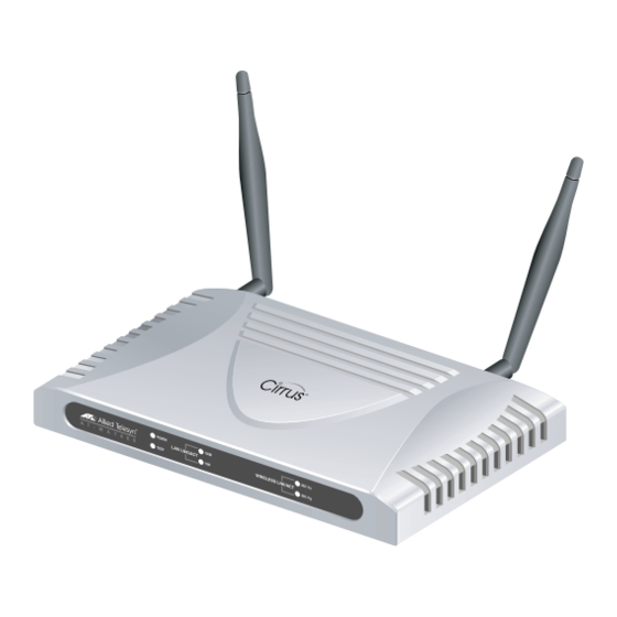
AT-WA7400 Wireless Access Point Installation Guide Front and Back Panels Figure 1 shows the AT-WA7400 Wireless Access Point. Figure 1. AT-WA7400 Wireless Access Point... - Page 24 Chapter 1: Overview Figure 2 shows the front and back panels of the wireless access point. System LEDs LAN LEDs Wireless LEDs RESET TO DEFAULT 5V,2.8A Reset Button LAN Port Power Connector Antenna Connectors Figure 2. Front and Back Panels...
-
Page 25: Leds
AT-WA7400 Wireless Access Point Installation Guide LEDs The system LEDs on the AT-WA7400 Wireless Access Point are described in Table 2. Table 2. System LEDs State Description Power The access point is not receiving power. Green The access point is receiving power. - Page 26 Chapter 1: Overview Table 3. LAN LEDs (Continued) State Description The access point is not operating at 10 Mbps. Blinking The access point is sending or receiving data at 10 Mbps. The Wireless LEDs are described in Table 4. Table 4. Wireless LEDs State Description LNK/ACT...
-
Page 27: Chapter 2: Installation
Chapter 2 Installation This chapter contains the following sections: “Reviewing Safety Precautions” on page 26 “Installation Guidelines” on page 28 “Unpacking the Access Point” on page 30 “Installing the Antennas” on page 31 “Using the Access Point on a Desktop” on page 33 “Mounting an Access Point on a Wall”... -
Page 28: Reviewing Safety Precautions
Chapter 2: Installation Reviewing Safety Precautions Please review the following safety precautions before you begin to install the AT-WA7400 Wireless Access Point. Note indicates that a translation of the safety statement is available in a PDF document titled “Translated Safety Statements”... - Page 29 AT-WA7400 Wireless Access Point Installation Guide Pluggable Equipment. The socket outlet shall be installed near the equipment and shall be easily accessible. Warning: Operating Temperature. This product is designed for a maximum ambient temperature of 40° degrees C. All Countries: Install product in accordance with local and National Electrical Codes.
-
Page 30: Installation Guidelines
Allied Telesis recommends that you have an Allied Telesis- certified RF specialist conduct a site survey to determine the ideal locations for all your Allied Telesis wireless network devices. To conduct a proper site survey, you need to have special equipment and training. -
Page 31: Microwave Ovens
AT-WA7400 Wireless Access Point Installation Guide Microwave Ovens Microwave ovens operate in the same frequency band as 802.11g and 802.11b radios; therefore, if you use a microwave oven within range of your wireless network, you may notice network performance degradation. Both your microwave oven and your... -
Page 32: Unpacking The Access Point
Chapter 2: Installation Unpacking the Access Point To unpack the AT-WA7400 Wireless Access Point, perform the following procedure: 1. Remove all components from the shipping package. Note Store the packing material in a safe location. You must use the original shipping material if you need to return the unit to Allied Telesis. -
Page 33: Installing The Antennas
Installing the Antennas To install the antennas, perform the following procedure: 1. Remove the antennas from their package. 2. Locate the antenna connectors in the back of the AT-WA7400 Wireless Access Point, as shown in Figure 3. 5 V ,2 R E S .8 A... - Page 34 Chapter 2: Installation 3. Screw one antenna into each antenna connector, as shown in Figure 4. 5 V ,2 R E S .8 A E T T E F A U L T L A N Figure 4. Attaching the Antennas You can point the antennas in the direction that provides the best signal strength.
-
Page 35: Using The Access Point On A Desktop
AT-WA7400 Wireless Access Point Installation Guide Using the Access Point on a Desktop You can place the AT-WA7400 Wireless Access Point on a desktop or other flat surface. To place the AT-WA7400 Wireless Access Point on a desktop, perform the following procedure: 1. -
Page 36: Mounting An Access Point On A Wall
Chapter 2: Installation Mounting an Access Point on a Wall To mount the AT-WA7400 Wireless Access Point on a wall, perform the following procedure: 1. Select a wall location and mark two hole locations for the anchors 98.425 mm (3.875 in.) apart. - Page 37 AT-WA7400 Wireless Access Point Installation Guide 4. Align the keyholes on the back with the screw heads, as shown in Figure 6. Figure 6. Aligning the Access Point for Mounting on the Wall 5. Place the keyhole slots on the bottom of the access point over the screw heads.
-
Page 38: Mounting The Access Point On A Metal Surface
Chapter 2: Installation Mounting the Access Point on a Metal Surface To mount the AT-WA7400 Wireless Access Point on a metal surface, perform the following procedure: 1. Select a location for the access point. 2. Turn the access point over and place it on a secure surface. -
Page 39: Connecting The Access Point To The Lan
AT-WA7400 Wireless Access Point Installation Guide Connecting the Access Point to the LAN To connect the AT-WA7400 Wireless Access Point to the LAN, perform the following procedure: 1. Locate the RJ45 cable in the box. 2. Connect one end of the cable to the LAN. -
Page 40: Powering On The Access Point
Chapter 2: Installation Powering On the Access Point To power on the access point, perform the following procedure: Warning: Do not work on equipment or cables during periods of lightning activity. Warning: Power cord is used as a disconnection device. To de-energize equipment, disconnect the power cord. - Page 41 AT-WA7400 Wireless Access Point Installation Guide b. Plug a LAN cable from a unit that supports PoE into the LAN port, as shown in Figure 10. No other power connection is required. 5 V ,2 R E S .8 A...
-
Page 42: Running Kickstart To Find Access Points On The Network
Running KickStart to Find Access Points on the Network KickStart is an easy-to-use utility for discovering and identifying new AT-WA7400 Wireless Access Points. KickStart scans the network looking for access points, displays ID details on those it finds, and provides access to the AT-WA7400 Management Software. - Page 43 Ethernet port on the your PC. 2. Insert the AT-WA7400 Wireless Access Point CD into the CD- ROM drive on your computer. The CD’s main page is shown in Figure 11.
- Page 44 Chapter 2: Installation The KickStart page, as shown in Figure 12, provides two options: Open KickStart and Install KickStart. Figure 12. KickStart Page For information about installing KickStart, refer to “Installing KickStart on the Administrator’s PC” on page 47. Otherwise, continue with this procedure.
- Page 45 AT-WA7400 Wireless Access Point Installation Guide The KickStart Welcome page is displayed, as shown in Figure 13. Figure 13. KickStart Welcome Page 5. Click Next to search for access points.
- Page 46 Figure 14. KickStart Search Results Page Note The KickStart utility only finds other AT-WA7400 Wireless Access Points. If KickStart does not find the AT-WA7400 Wireless Access Point you just installed, an informational window is displayed with troubleshooting information about your LAN and power connections.
- Page 47 The Administration dialog box opens, as shown in Figure 15. Figure 15. Administration Dialog Box Note KickStart provides a link to the AT-WA7400 management software web pages via the IP address of the first access point of each model. The AT-WA7400 management software is a centralized management tool that you can access through the IP address for any access point in a cluster.
- Page 48 Chapter 2: Installation After your other access points are configured, you can also link to the AT-WA7400 management software web pages using the IP address for any of the other AT-WA7400 Wireless Access Points, for example http:// IPAddressOfAccessPoint . 9. Click Administration.
-
Page 49: Installing Kickstart On The Administrator's Pc
To install the KickStart utility on the administrator’s PC, perform the following procedure: 1. Insert the AT-WA7400 Wireless Access Point CD into the CD- ROM drive on your computer. The CD’s main page is shown in Figure 11 on page 41. - Page 50 Chapter 2: Installation 2. Click KickStart Utility. The KickStart page, as shown in Figure 12 on page 42, provides two options: Open KickStart and Install KickStart. The Open KickStart option is described in “Running KickStart to Find Access Points on the Network” on page 40. 3.
- Page 51 AT-WA7400 Wireless Access Point Installation Guide The Select Installation Folder dialog box is shown in Figure 19. Figure 19. Select Installation Folder Dialog Box 5. Do one of the following: To see how much disk space the files require, click Disk...
- Page 52 Chapter 2: Installation The KickStart Setup Disk Space dialog box is shown in Figure 20. Figure 20. KickStart Setup Disk Space Dialog box Select the drive where you want to install KickStart, and then click OK. Click Browse to select a specific location for the KickStart utility.
- Page 53 AT-WA7400 Wireless Access Point Installation Guide The KickStart Setup confirmation dialog box is shown in Figure 21. Figure 21. KickStart Installation Confirmation Dialog Box 7. Click Next to start the installation.
- Page 54 Chapter 2: Installation The Installing KickStart dialog box is shown in Figure 22. Figure 22. Installing KickStart Dialog Box...
- Page 55 AT-WA7400 Wireless Access Point Installation Guide When the installation is complete, the Installation Complete dialog box is displayed, as shown in Figure 23. Figure 23. KickStart Installation Complete Dialog Box 8. Click Close. You can now run KickStart from the Programs folder under...
-
Page 56: Warranty Registration
Chapter 2: Installation Warranty Registration After installing your access point, you can register your product by completing the enclosed warranty card and sending it to Allied Telesis. -
Page 57: Chapter 3: Troubleshooting
Chapter 3 Troubleshooting If the AT-WA7400 Wireless Access Point is not operating correctly, do one of the following: Press the Reset to Default button once to reboot the access point. You can also reset the access point through the AT-S77 management software. - Page 58 Chapter 3: Troubleshooting...
-
Page 59: Appendix A: Technical Specifications
Appendix A Technical Specifications Physical Specifications Dimensions: 176.34 mm x 103.62 mm x 23.20 mm (W x D x H) (6.94 in. x 4.07 in. x .91 in.) Weight: 250 g (8.81 oz.) Environmental Specifications Operating Temperature: 0 to 50°C Storage Temperature: -20 to 70°C Operating Humidity:... - Page 60 Appendix A: Technical Specifications 300 328; EN 301 489 Transmitter EMC; Canada IC; CE Mark emission/ immunity; CE Marked (compliant with RTT&E, EMC, LVD Directives); C-Tick Electrical Safety: UL 60950-1, CSA C22.2 No. 60950-1- 03 ( ), EN60950-1 (TUV); TUV, EN 60593-IP53...
-
Page 61: Appendix B Radio Bands
Appendix B Radio Bands Allied Telesis’s AT-WA7400 Wireless Access Point is capable of operating in the 2.4GHZ (IEEE 802.11g/b) AND in the 5GHZ band (IEEE 802.11a) simultaneously. The access point is shipped with the 802.11g/b radio enabled and is software upgradeable to operate in 802.11g/b and 802.11a. - Page 62 Appendix B: Radio Bands...
Need help?
Do you have a question about the AT-WA7400 and is the answer not in the manual?
Questions and answers