Allied Telesis AT-WA7400 Installation Manual
Hide thumbs
Also See for AT-WA7400:
- Installation manual (62 pages) ,
- Datasheet (2 pages) ,
- Specifications (2 pages)
Table of Contents
Advertisement
Quick Links
Download this manual
See also:
Installation Manual
Advertisement
Table of Contents

Related Manuals for Allied Telesis AT-WA7400


Summary of Contents for Allied Telesis AT-WA7400
-
Page 1: Wireless Access Point
Wireless Access Point AT-WA7400 Installation Guide PN 613-000164 Rev A... - Page 2 Copyright © 2005 Allied Telesyn, Inc. All rights reserved. No part of this publication may be reproduced without prior written permission from Allied Telesyn, Inc. Ethernet is a registered trademark of Xerox Corporation. All other product names, company names, logos or other designations mentioned herein are trademarks or registered trademarks of their respective owners.
-
Page 3: Electrical Safety And Emissions Standards
Declares that the product: Wireless Access Point Model Numbers: AT-WA7400 This product complies with FCC Part 15B, Class B Limits: This device complies with part 15 of the FCC Rules. Operation is subject to the following two conditions: (1) This device must not cause harmful interference, and (2) this device must accept any interference received, including interference that may cause undesired operation. - Page 4 RFI Emissions FCC Class B, EN55022 Class B, CTICK, CE Immunity EN55024 Electrical Safety EN60950 (TUV), UL 60950 (...
-
Page 5: Translated Safety Statements
AT-WA7400 Wireless Access Point Installation Guide Translated Safety Statements Important: When you see the , go to the Allied Telesyn website www.alliedtelesyn.com for the translated safety statement in your language. -
Page 7: Table Of Contents
Contents Electrical Safety and Emissions Standards ........3 Translated Safety Statements ............... 5 Preface ....................13 Safety Symbols Used in this Guide ............. 14 Where to Find Web-based Guides ............15 Contacting Allied Telesyn..............16 Online Support ................16 Email and Telephone Support............. 16 Returning Products.............. - Page 8 Contents Warranty Registration................45 Chapter 3: Troubleshooting ............47 Appendix A: Technical Specifications ........... 49 Physical Specifications................ 49 Environmental Specifications .............. 49 Power Specifications ................49 Safety and Electromagnetic Emissions Certifications ......49...
- Page 9 Figures Figure 1: AT-WA7400 Wireless Access Point ........21 Figure 2: Front and Back Panels............21 Figure 3: Location of the Antenna Connectors........31 Figure 4: Attaching the Antennas ............31 Figure 5: Attaching the Rubber Feet ........... 33 Figure 6: Aligning the Access Point for Mounting on the Wall..... 35 Figure 7: Attaching the Magnets ............
- Page 10 Figures...
- Page 11 Tables Table 1. Safety Symbols ..............14 Table 2. System LEDs ............... 22 Table 3. LAN LEDs ................22 Table 4. Wireless LEDs ..............23...
- Page 12 Tables...
-
Page 13: Preface
Preface This guide contains instructions on how to install the Cirrus™ AT-WA7400 Wireless Access Point. This preface contains the following sections: “Safety Symbols Used in this Guide” on page 14 “Where to Find Web-based Guides” on page 15 “Contacting Allied Telesyn” on page 16... -
Page 14: Safety Symbols Used In This Guide
Preface Safety Symbols Used in this Guide This document uses the safety symbols defined in Table 1. Table 1. Safety Symbols Symbol Meaning Description Caution Performing or omitting a specific action may result in equipment damage or loss of data. Warning Performing or omitting a specific action may result in electrical shock. -
Page 15: Where To Find Web-Based Guides
AT-WA7400 Wireless Access Point Installation Guide Where to Find Web-based Guides The installation and user guides for all Allied Telesyn products are available in portable document format (PDF) on our web site at www.alliedtelesyn.com. You can view the documents online or... -
Page 16: Contacting Allied Telesyn
Preface Contacting Allied Telesyn This section provides Allied Telesyn contact information for technical support as well as sales and corporate information. Online Support You can request technical support online by accessing the Allied Telesyn Knowledge Base: http://kb.alliedtelesyn.com. You can use the Knowledge Base to submit questions to our technical support staff and review answers to previously asked questions. - Page 17 AT-WA7400 Wireless Access Point Installation Guide Allied Telesyn web site: www.alliedtelesyn.com Allied Telesyn FTP server: ftp://ftp.alliedtelesyn.com If you prefer to download new software from the Allied Telesyn FTP server from your workstation’s command prompt, you will need FTP client software and you must log in to the server. Enter “anonymous” for...
- Page 18 Preface...
-
Page 19: Chapter 1: Overview
Chapter 1 Overview The Cirrus™ AT-WA7400 Wireless Access Point is a wireless communications hub for devices on your network. It provides continuous, high-speed access between your wireless and Ethernet devices. You administer the AT-WA7400 Wireless Access Point using the AT-WA7400 management software. -
Page 20: Features
Chapter 1: Overview Features The features of the AT-WA7400 Wireless Access Point include: High performance 108 Mbps (802.11g - 802.11a with upgrade) data rate Security support via 802.11i (WPA2), WPA-PSK, TKIP, AES, IEEE 802.1x, and EAP/802.1 Multiple BSSID and Virtual LAN (VLANs) -
Page 21: Front And Back Panels
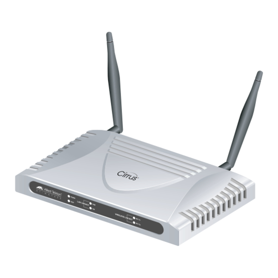
AT-WA7400 Installation Guide Front and Back Panels Figure 1 shows the AT-WA7400 Wireless Access Point. Figure 1. AT-WA7400 Wireless Access Point Figure 2 shows the front and back panels of the wireless access point. System LEDs LAN LEDs Wireless LEDs RESET TO DEFAULT 5V,2.8A... -
Page 22: Leds
Chapter 1: Overview LEDs The system LEDs on the AT-WA7400 Wireless Access Point are described in Table 2. Table 2. System LEDs State Description Power The access point is not receiving power. Green The access point is receiving power. Test No system maintenance in progress. -
Page 23: Table 4. Wireless Leds
AT-WA7400 Installation Guide Table 3. LAN LEDs (Continued) State Description Blinking The access point is sending or receiving data at 10 Mbps. The Wireless LEDs are described in Table 4. Table 4. Wireless LEDs State Description LNK/ACT No link is detected. - Page 24 Chapter 1: Overview...
-
Page 25: Chapter 2: Installation
Chapter 2 Installation This chapter contains the following sections: “Reviewing Safety Precautions” on page 26 “Installation Guidelines” on page 28 “Unpacking the Access Point” on page 30 “Installing the Antennas” on page 31 “Using the Access Point on a Desktop” on page 33 “Mounting an Access Point on a Wall”... -
Page 26: Reviewing Safety Precautions
Chapter 2: Installation Reviewing Safety Precautions Please review the following safety precautions before you begin to install the AT-WA7400 Wireless Access Point. Note When you see the , go to the Allied Telesyn web site for translated safety statements. Warning: To prevent electric shock, do not remove the cover. - Page 27 AT-WA7400 Wireless Access Point Installation Guide Caution: Do not install in direct sunlight, or a damp or dusty place.
-
Page 28: Installation Guidelines
Chapter 2: Installation Installation Guidelines Allied Telesyn recommends that you have an Allied Telesyn-certified RF specialist conduct a site survey to determine the ideal locations for all your Allied Telesyn wireless network devices. To conduct a proper site survey, you need to have special equipment and training. The following general practices should be followed in any installation: Locate access points centrally within areas requiring coverage. -
Page 29: Cordless Telephones
AT-WA7400 Wireless Access Point Installation Guide microwave oven out of range of your access point. Cordless Telephones If you have an 802.11g or 802.11b radio in your access point, the radio may experience interference from some cordless telephones. For optimal performance, consider operating cordless telephones out of range of your access points. -
Page 30: Unpacking The Access Point
Chapter 2: Installation Unpacking the Access Point To unpack the AT-WA7400 Wireless Access Point, perform the following procedure: 1. Remove all components from the shipping pckage. Note Store the packing material in a safe location. You must use the original shipping material if you need to return the unit to Allied Telesyn. -
Page 31: Installing The Antennas
Installing the Antennas To install the antennas, perform the following procedure: 1. Remove the antennas from their package. 2. Locate the antenna connectors in the back of the AT-WA7400 Wireless Access Point, as shown in Figure 3. 5 V ,2 R E S .8 A... - Page 32 Chapter 2: Installation You can point the antennas in the direction that provides the best signal strength.
-
Page 33: Using The Access Point On A Desktop
AT-WA7400 Wireless Access Point Installation Guide Using the Access Point on a Desktop You can place the AT-WA7400 Wireless Access Point on a desktop or other flat surface. To place the AT-WA7400 Wireless Access Point on a desktop, perform the following procedure: 1. -
Page 34: Mounting An Access Point On A Wall
Chapter 2: Installation Mounting an Access Point on a Wall To mount the AT-WA7400 Wireless Access Point on a wall, perform the following procedure: 1. Select a wall location and mark two hole locations for the anchors 98.425 mm (3.875 in.) apart. -
Page 35: Figure 6: Aligning The Access Point For Mounting On The Wall
AT-WA7400 Wireless Access Point Installation Guide 4. Align the keyholds on the back with the screw heads, as shown in Figure 6. Figure 6. Aligning the Access Point for Mounting on the Wall 5. Place the keyhole slots on the bottom of the access point over the screw heads. -
Page 36: Mounting The Access Point On A Metal Surface
Chapter 2: Installation Mounting the Access Point on a Metal Surface To mount the AT-WA7400 Wireless Access Point on a metal surface, perform the following procedure: 1. Select a location for the access point. 2. Turn the access point over and place it on a secure surface. -
Page 37: Connecting The Access Point To The Lan
AT-WA7400 Wireless Access Point Installation Guide Connecting the Access Point to the LAN To connect the AT-WA7400 Wireless Access Point to the LAN, perform the following procedure: 1. Locate the RJ45 cable in the box. 2. Connect one end of the cable to the LAN. -
Page 38: Powering On The Access Point
Chapter 2: Installation Powering On the Access Point To power on the access point, perform the following procedure: 1. Do one of the following: Warning: Do not work on equipment or cables during periods of lightning activity. Warning: Power cord is used as a disconnection device. To de-energize equipment, disconnect the power cord. -
Page 39: Figure 10: Poe Connection
AT-WA7400 Wireless Access Point Installation Guide c. Plug a LAN cable from a unit that supports PoE into the LAN port, as shown in Figure 10. No other power connection is required. 5 V ,2 R E S .8 A... -
Page 40: Starting A Management Session
Ethernet port on the your PC. 2. Insert the AT-WA7400 Wireless Access Point CD into the CD- ROM drive on your computer. The CD starts up and displays a menu, as shown in Figure 11. -
Page 41: Figure 12: Kickstart Welcome Dialog Box
AT-WA7400 Wireless Access Point Installation Guide 3. Click KickStart Utility. The Kickstart Welcome dialog box is displayed, as shown in Figure 12. Figure 12. KickStart Welcome Dialog Box 4. Click Next to search for access points. -
Page 42: Figure 13: Kickstart Search Results Dialog Box
Note The KickStart utility only finds other AT-WA7400 Wireless Access Points. If KickStart does not find the AT-WA7400 Wireless Access Point you just installed, an informational window is displayed with troubleshooting information about your LAN and power connections. 5. Review the list of access points that KickStart found, as shown in the example in Figure 13. -
Page 43: Figure 14: Administration Dialog Box
AT-WA7400 Wireless Access Point Installation Guide 7. Click Next. The Administration dialog box opens, as shown in Figure 14. Figure 14. Administration Dialog Box 8. Click Administration. You are prompted for a user name and password, as shown in Figure 15. -
Page 44: Figure 16: Basic Settings Page
9. Enter the user name and password and click OK. The Basic Settings page opens, as shown in Figure 16. Figure 16. Basic Settings Page Refer to the AT-WA7400 Management Software User’s Guide for information about how to configure the basic settings. -
Page 45: Warranty Registration
AT-WA7400 Wireless Access Point Installation Guide Warranty Registration After installing your access point, you can register your product by completing the enclosed warranty card and sending it to Allied Telesyn,’... - Page 46 Chapter 2: Installation...
-
Page 47: Chapter 3: Troubleshooting
Chapter 3 Troubleshooting If the AT-WA7400 Wireless Access Point is not operating correctly, do one of the following: Press the Reset to Default button once to reboot the access point. You can also reset the access point through the AT-S77 management software. - Page 48 Chapter 3: Troubleshooting...
-
Page 49: Appendix A: Technical Specifications
Appendix A Technical Specifications Physical Specifications Dimensions: 176.34 mm x 103.62 mm x 23.20 mm (W x D x H) (6.94 in. x 4.07 in. x .91 in.) Weight: 250 g (8.81 oz.) Environmental Specifications Operating Temperature: 0 to 85°C Storage Temperature: -20 to 70°C Operating Humidity:... - Page 50 Appendix A: Technical Specifications Immunity: Canada IC; CE Mark; CE Marked, compliant with RTT&E, EMC, LVD Directives; C-Tick Electrical Safety: UL 1950/C22.2#950 IEC; TUV; EN 60950; EN 60593-IP53...
-
Page 51: Federal Communication Commission Interference Statement
Federal Communication Commission Interference Statement This equipment has been tested and found to comply with the limits for a Class B digital device, pursuant to Part 15 of the FCC Rules. These limits are designed to provide reasonable protection agai nst harmful interference in a residential installation.
Need help?
Do you have a question about the AT-WA7400 and is the answer not in the manual?
Questions and answers