Table of Contents
Advertisement
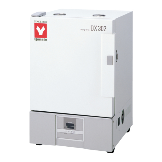
Constant Temperature
Drying Oven
Model DX302/402/602
● Thank you very much for purchasing this Yamato DX
series constant temperature drying oven.
● Please
read
"Warranty" before operating this unit to assure proper
operation. After reading these documents, be sure to
store them securely together with the "Warranty" at a
handy place for future reference.
Warning!
to
read
important
instructions.
Yamato Scientific Co., Ltd.
Fourth edition
the
"Operating
Before operating the unit, be sure
carefully
and
warnings
in
Instructions"
and
fully
understand
the
operating
Advertisement
Table of Contents

Related Manuals for Yamato DX302


Summary of Contents for Yamato DX302
- Page 1 After reading these documents, be sure to store them securely together with the “Warranty” at a handy place for future reference. Warning! Before operating the unit, be sure read carefully fully understand important warnings operating instructions. Yamato Scientific Co., Ltd.
-
Page 2: Table Of Contents
Table of Contents 1. Safety precautions ........................1 Explanation of pictograms........................1 List of symbols ..........................2 Warning・Cautions ..........................3 2. Before operating the unit ......................4 Precautions when installing the unit ....................4 3. Names and functions of parts ......................9 Main body ............................9 Operation panel ..........................10 Explanation of characters.......................11 4. -
Page 3: Safety Precautions
1. Safety precautions Explanation of pictograms About pictograms A variety of pictograms are indicated in this operating instruction and on products to assure safe operation. Possible results from improper operation ignoring them are classified as follows. Be sure to fully understand the descriptions below before proceeding to the text. Indicates a situation which may result in death or serious injury Warning (Note 1) -
Page 4: List Of Symbols
1.Safety precautions List of symbols Warning Danger!: Danger!: Danger!: Danger!:Hazard of General warnings High voltage High temperature Moving part explosion Caution Caution for no Caution for water General cautions Electrical shock! Burning! liquid heating! leak! Poisonous For water only material Prohibitions Do not General bans... -
Page 5: Warning・Cautions
1. Safety precautions Warning・Cautions Warning Never operate the unit in an atmosphere containing flammable or explosive gas Never operate the unit in an atmosphere containing flammable or explosive gas. Otherwise, an explosion or a fire may result since the unit is not explosion-proof. See section “Never operate the unit in an atmosphere containing flammable or explosive gas. -
Page 6: Before Operating The Unit
2. Before operating the unit Precautions when installing the unit 1. Carefully select an installation site. Take special care not to install the unit at a place described below: ・On uneven or dirty floor ・Where combustible gas or corrosive gas exists ・Where the ambient temperature is 35°C or more ・Where temperature fluctuates widely ・Where dust or humidity is excessive... - Page 7 2. Before operating the unit Precautions when installing the unit 3. Never use the unit with an explosive material, a flammable material or a material containing them. Never use the unit with an explosive material, a flammable material or a material containing them.
- Page 8 2. Before operating the unit Precautions when installing the unit 6. Do not overload shelves. 7. Do not place too many samples. Withstand load of each shelf board is Too many samples may prevent proper 15kg in uniform loading. Place samples in temperature control.
- Page 9 11. Be sure to connect the power plug to the dedicated power distribution panel or a wall outlet. Use a power distribution panel or a wall outlet that meets the electrical capacity of the unit. Electrical DX302 AC100V 9.5A capacity:...
- Page 10 2. Before operating the unit Precautions when installing the unit 12. Handling of a power cord Never use electrical power cords bundled. When these are used bundled, they might overheat causing a fire. Do not convert, forcibly bend, twist or pull the power cord. Otherwise, a fire or an electrical shock may result.
-
Page 11: Names And Functions Of Parts
3. Names and functions of parts Main body Front panel Door Rating sticker Standalone overheat Handle protection device (Thermostat) Main switch (Earth leakage breaker) Control panel Rear panel Exhaust port Power cord... -
Page 12: Operation Panel
3. Names and functions of parts Operation panel MEASURED TEMP. ⑥ ⑤ ℃ ⑦ ④ HEATER SET TEMP. ① ③ TIMER STOP SUBMENU ② Name Operation/action RUN/STOP key Used for starting/stoping operation. ① Used for selecting settings. ▼▲ keys ② TIMER key Key for selecting timer operation settings. -
Page 13: Explanation Of Characters
3. Names and functions of parts Explanation of characters Characters on the controller are explained in this section. Characters Identifier Name Application AStP Auto stop setting Used for setting auto stop operation. AStr Auto start setting Used for setting auto start operation. Displayed when timer operation has Time up ended. -
Page 14: Operating Procedures
4. Operating procedures List of operation modes and functions Operation modes of the unit are as shown below: № Name Description Page Turning the ELB on to enter the operation setting mode. Fixed temperature Proceed to temperature setting that uses ▼▲ keys. P.16 operation Pressing the RUN/STOP key longer to start operation, and... - Page 15 4. Operating procedures List of operation modes and functions Functions of the unit are as shown below: Name Description Page № Automatic overheat prevention function: This function is linked to the unit set temperature and has been set to so that it is automatically activated (returned automatically) at a temperature 12℃...
-
Page 16: Operation Mode・Function Setting Keys And Characters
4. Operating procedures Operation mode・function setting keys and characters Key operations and characters in the diagram below are used for operation mode and function settings. ELB ON Fixed temp. Function Timer operation operation setting TIMER Long press MENU Temperature setting ▲... -
Page 17: Operating Procedures (Settings For Standalone Overheat Prevention Device (Thermostat))
4. Operating procedures Operating procedures (settings for Standalone overheat prevention device (Thermostat)) As a safety measure for preventing overheat, a standalone overheat prevention device (Thermostat) hydraulic overheat prevention device (manual return) is installed. Temperature setting range and functions The temperature setting range for the standalone overheat prevention device (Thermostat) is “50 ~ 350 .”... -
Page 18: Operating Procedures (Fixed Temperature Operation)
4. Operating procedures Operating procedures (fixed temperature operation) How to start fixed temperature operation 1.Turn the ELB ON. (Turn the ELB to “ON.”) When the ELB is turned ON, the intial values will be displayed for about four seconds, then the initial screen will appear and the current bath temperature and the previous set temperature are displayed on each of the indicators. -
Page 19: Operating Procedures (Quick Auto Stop Operation)
4. Operating procedures Operating procedures (quick auto stop operation) Used when you want to “stop fixed temperature operation being performed automatically in several hours. Quick auto stop operation is a function to enable auto stop timer setting during operation. Procedures for quick auto 1. - Page 20 4. Operating procedures Operating procedures (quick auto stop operation) When you want to change settings, press the ▼▲ keys on When you want to correct set the current screen to enter the setting mode where you can temperature or set time, or change settings.
-
Page 21: Operating Procedures (Auto Stop Operation)
4. Operating procedures Operating procedures (auto stop operation) This mode automatically stops fixed temperature operation after a certain time from its start set with the timer. Procedures for auto stop 1. Setting a stop time ① After confirming the temperature you want is set, operation Press TIMER... - Page 22 4. Operating procedures Operating procedures (auto stop operation) When you want to change settings, press the ▼▲ keys on When you want to correct set the current screen to enter the setting mode where you can temperature or set time, or change settings.
-
Page 23: Operating Procedures (Auto Start Operation)
4. Operating procedures Operating procedures (auto start operation) This mode automatically starts fixed value operation after a certain time from its start set with the timer. However, operation does not stop automatically but needs to be stopped manually. Procedures for auto start 1. - Page 24 4. Operating procedures Operating procedures (auto start operation) When you want to change the set temperature during timer counting, When you want to press the ▼▲ keys during that status to switch the set temperature correct set tempera- screen to the set temperature input mode, which blinks to enable ture or set time, or change of the set temperature with the ▼▲...
-
Page 25: Useful Functions (Calibration Offset Function)
4. Operating procedures Useful functions (calibration offset function) Calibration offset function compensates any differences Using the calibration offset between the target temperature in the bath and the control function temperature of the controller (sensor temperature.) The function can compensate in parallel to either plus or minus side for the whole temperature band of the unit. -
Page 26: Useful Function (Setting Lock Function)
4. Operating procedures Useful function (setting lock function) This function locks the set operation status. Using the lock function The temperature is set at “off” on shipping from the factory. ① Press the TIMER key (SUB MENU key) long to enter the sub menu mode. -
Page 27: Useful Function (Power Outage Compensation Function)
4. Operating procedures Useful function (power outage compensation function) The power outage compensation function returns the main Using the power outage unit operation to the resume status after recovery from power compensation function outage, or keeps the current stop status. The function is set at “on”... -
Page 28: Cautions On Handling
5. Cautions on handling Warning 1. About handling of flammable or combustible solution The unit is not explosion proof. Take special care for handling samples on which explosive substances, combustible substances or substances containing them. Flammable or combustible solution will evaporate when left at a room temperature (or at a lower temperature for some types of solutions) and may be ignited and explode from switches, lights and other ignitable sources. - Page 29 7. Always operate the unit at a correct ambient temperature. Operational temperature range for the model DX302/402 is room temperature +5 ℃~ 300 ℃ ;DX602 room temperature +5 ℃~ 280 ℃ .
-
Page 30: Maintenance Procedures
6. Maintenance procedures Daily inspection/maintenance Be sure to perform daily inspection and maintenance to assure reliable operation of the unit. Warning Be sure to pull out the power cord unless necessary before trying to do inspection and ● maintenance works. Start these works after the device has returned to the normal temperature. -
Page 31: When The Unit Is Not To Be Used For A Long Time Or When Disposing
7. When the unit is not to be used for a long time or when disposing When the unit is not to be used for a long time or when disposing Caution Warning When the unit is not going to be used for a long When disposing the unit time ●... -
Page 32: Troubleshooting
8. Troubleshooting Safety device and error codes The unit has the self diagnostic function with a controller and a separate safety device. Table below shows possible causes and measures when the safety device is triggered. [Error codes] When a functional or mechanical abnormality occurs, an error code will be displayed on the control panel. -
Page 33: When A Malfunction Is Suspected
8. Troubleshooting When a malfunction is suspected If any of the symptoms below occurs Symptom Check If the power cord is connected to the power supply securely. ● Turning the ELB to on will If power outage is not occurring. ●... -
Page 34: After Sales Service And Warranty
9. After sales service and warranty When requesting a repair When requesting a repair If any trouble occurs, immediately stop operation, turn the ELB off, pull out the power plug and contact your dealer or our sales office. Information necessary for requesting a repair ◆... -
Page 35: Specifications
10. Specifications Model DX302 DX402 DX602 40 ℃~ 300 ℃ 40 ℃~ 280 ℃ Temperature control range At no load and at an ambient temperature of 23 ℃ Temperature ± 1 ℃( setting: 300 ℃ , exhaust port fully opened )... -
Page 36: Wiring Diagram
11. Wiring diagram DX302/402/602 X2-1 X2-2 AC100V CONT Symbol Part name Symbol Part name Standalone overheat prevention Earth leakage breaker device (Thermostat) Temperature sensor H1, H2 Heater (K-thermocouple) Terminal block CONT Planar board Display circuit board X1, X2 Relay... -
Page 37: List Of Replacement Parts
12. List of replacement parts Common parts Symbol Part name Code No. Specifications Manufacturer Temperature sensor 1-16-003-0049 LCK-M1-2000Y K single Yamato CONT Planar board LT00007640 CN40B-Y Yamato Display circuit board LT00007639 CN40B-Y Yamato Tough card 1-13-000-0009 50 ㎜ Yamato Relay LT00032865 FC-0T 1b 100V Fuji... -
Page 38: List Of Dangerous Materials
13. List of dangerous materials Never use an explosive substance a flammable substance or a substance containing them for this device. ① Nitroglycol, glycerine trinitrate, cellulose nitrate and other explosive nitrate esters ② Trinitrobenzen, trinitrotoluenem, picric acid and other explosive nitro compounds ③... -
Page 39: Standard Installation Manual
14. Standard installation manual * Install the product according to the following: (Confirm separately for optional items or special specifications) Installation mgr. Judg Model Serial number Date Installation mgr. (company name) ment TOC No. Reference page of the Judg Item Implementation method №... - Page 40 Be sure to use the unit strictly following the handling and operating instructions in this operating instruction. Yamato Scientific Co., Ltd. assumes no responsibility for an accident or a malfunction caused by use of this product in any way not specified in this operating instruction.
Need help?
Do you have a question about the DX302 and is the answer not in the manual?
Questions and answers