Table of Contents
Advertisement
Quick Links
Constant Temperature
Drying Oven
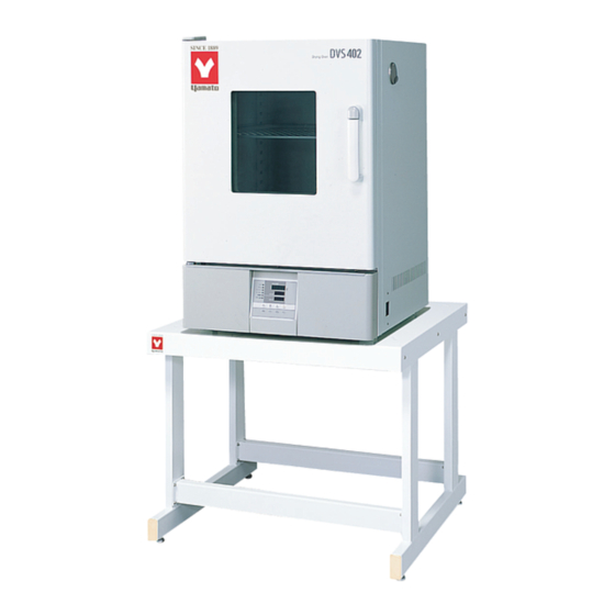
DVS402C/DVS602C
DVS412C/DVS612C
- Second Edition -
Thank you very much for purchasing this Yamato DVS series
constant temperature drying oven.
Please read the "Operating Instructions" and "Warranty"
before operating this unit to assure proper operation. After
reading these documents, be sure to store them securely
together for future reference.
WARNING!
Carefully read and thoroughly understand the important
warning items described in this manual before using this
unit.
Yamato Scientific America Inc.
Model
Advertisement
Table of Contents

Subscribe to Our Youtube Channel
Related Manuals for Yamato DVS402C


Summary of Contents for Yamato DVS402C
- Page 1 Model DVS402C/DVS602C DVS412C/DVS612C - Second Edition - Thank you very much for purchasing this Yamato DVS series constant temperature drying oven. Please read the “Operating Instructions” and “Warranty” before operating this unit to assure proper operation. After reading these documents, be sure to store them securely together for future reference.
-
Page 2: Table Of Contents
Table of contents 1. Safety precautions ........................1 Explanation of symbols........................1 List of symbols..........................2 Warning・Cautions .........................3 2. Before operating the unit ......................4 Precautions when installing the unit ....................4 3. Names and functions of parts ......................9 Main body............................9 Operation panel ..........................10 Explanation of characters ......................11 4. -
Page 3: Safety Precautions
1. Safety precautions Explanation of Symbols About Symbols A variety of symbols are indicated in this operating instruction and on products to assure safe operation. Possible results from improper operation ignoring them are classified as follows. Be sure to fully understand the descriptions below before proceeding to the text. Indicates a situation which may result in death or serious injury Warning (Note 1) -
Page 4: List Of Symbols
1. Safety precautions List of symbols Warning Danger! Danger! Danger! Danger! General warnings High voltage High temperature Moving part Hazard of explosion Caution Caution for no Caution for water General cautions Electrical shock! Burning! liquid heating! leak! Poisonous For water only material Prohibitions Do not... -
Page 5: Warning・Cautions
1. Safety precautions Warning・Cautions Warning Never operate the unit in an atmosphere containing flammable or explosive gas Never operate the unit in an atmosphere containing flammable or explosive gas. Otherwise, an explosion or a fire may result since the unit is not explosion-proof. See section “13. -
Page 6: Before Operating The Unit
2. Before operating the unit Precautions when installing the unit Warning 1. Be sure to connect the ground wire. ・ The DS402C/602C types use a single-phase 115V, DVS412C/612C types use a single-phase 220V power source. Please consult your local electrical contractor for power connecting work. - Page 7 2. Before operating the unit Precautions when installing the unit Warning 3. Never operate the unit in an atmosphere containing explosive or flammable gas Never operate the unit in an atmosphere containing flammable or explosive gas. Since the unit is not explosion-proof, an arc is discharged when turning a switch “ON” and “OFF” and during operation and a fire or an explosion may result.
- Page 8 2. Before operating the unit Precautions when installing the unit Warning 4. Do not alter the product. 5. Install the unit on a level surface The user shall never attempt to alter the Install the unit on a level surface. Flat unit since it may cause a malfunction.
- Page 9 Precautions when installing the unit Caution 8. Be sure to connect the power plug to the dedicated wall outlet. Use a power distribution panel or a wall outlet that meets the electrical capacity of the unit. Electric capacity: DVS402C AC115V 11.5A DVS412C AC220V 6.75A...
- Page 10 2. Before operating the unit Precautions when installing the unit Caution 11. About handling of the power cord Never use electrical power cords bundled. When these are used bundled, they might overheat causing a fire. Do not convert, forcibly bend, twist or pull the power cord. Otherwise, a fire or an electrical shock may result.
-
Page 11: Names And Functions Of Parts
3. Names and functions of parts Main body Front view Observation window Door Cable hole Caution plate Rating plate Handle Power switch(ELB) Control panel Rear View Exhaust port Power cord DVS412C/612C... -
Page 12: Operation Panel
3. Names and functions of parts Operation panel ⑧ ⑭ MEASURED TEMP. HEATER ⑨ ALARM ℃ AUTO STOP ⑩ AUTO START TEMP. ⑮ FIXED TEMP. ⑪ OVER TEMP. PROGRAM PROTECTOR ⑫ ⑯ ⑬ ① ENTER STOP ③ ② FIXED ⑦ TIMER PROGRAM TEMP. -
Page 13: Explanation Of Characters
3. Names and functions of parts Explanation of characters Characters on the VS4 type controller are explained in this section. Characters Identifier Name Application Fixed temperature Means settings for fixed temperature operation setting operation. Temperature setting Used for setting a temperature. AStP Auto stop setting Used for setting auto stop operation. - Page 14 3. Names and functions of parts Explanation of characters Characters Identifier Name Application Used for inputting a calibration offset temperature Calibration offset setting See section “Using the calibration offset function” on page 31. Used setting overheat Setting overheat protection device temperature. protection device See section “...
-
Page 15: Operating Procedures
4. Operating procedures List of operation modes and functions Operation modes of the unit are as shown below: Name Description Page № Pressing FIXED TEMP. enter fixed temperature operation setting mode. Pressing the FIXED TEMP. key again to enter the Fixed temperature temperature setting mode. - Page 16 4. Operating procedures List of operation modes and functions Operating functions of the unit are as shown below: Name Description Page № Automatic overheat prevention function: This function is linked to the unit set temperature and has been set to so that it is automatically activated (returned automatically) at a temperature 12℃...
-
Page 17: Operation Mode・Function Setting Keys And Characters
4. Operating procedures Operation mode・function setting keys and characters Key operations and characters in the diagram below are used for operation mode and function settings. ELB ON FIXED PRO- TIMER TEMP GRAM MENU MENU Fixed temp. Timer Programming operation operation ▼... -
Page 18: Settings For Overheat Prevention Device
4. Operating procedures Settings for overheat prevention device The safety device for preventing overheat has the automatic overheat prevention function for the controller (automatic recovery) and has the power supply, the display and the key input assembly in common with the controller as well as it has an overheat prevention device (manual recovery) as a secondary safety measures that consists of separate temperature measurement circuit, the CPU, the sensor and the output circuit. -
Page 19: Operating Procedures (Fixed Temperature Operation)
4. Operating procedures Operating procedures (fixed temperature operation) 1. Turn power ON. (Turn the ELB to ON.) How to start fixed When power is turned ON, the initial values will be displayed for temperature about four seconds, then the initial screen will appear and the operation current bath temperature, operation mode character and the overheat prevention set temperature are displayed on each of the... -
Page 20: Operating Procedures (Quick Auto Stop Operation)
4. Operating procedures Operating procedures (quick auto stop operation) Used when you want to, for example, “stop fixed temperature operation being performed automatically in several hours. Quick auto Procedures for quick stop operation is a function to enable auto stop timer setting during auto stop operation operation. -
Page 21: Operating Procedures (Auto Stop Operation)
4. Operating procedures Operating procedures (auto stop operation) Used when you want to “set automatic stop after set time has elapsed Procedures for auto from the start of the fixed temperature operation.” stop operation 1. Setting a stop time MEASURED TEMP. HEATER ①... - Page 22 4. Operating procedures Operating procedures (auto stop operation) 3. Stopping and ending timer operation MEASURED TEMP. HEATER Operation stops automatically when the set time comes. ALARM ℃ AUTO STOP The buzzer sounds for about five seconds to indicate operation has AUTO START TEMP.
-
Page 23: Operating Procedures (Auto Start Operation)
4. Operating procedures Operating procedures (auto start operation) Used when you want to “start operation automatically after the set Procedures for auto time.” start operation 1. Setting an operation start time MEASURED TEMP. HEATER ① Press the TIMER key in the initial screen. ALARM ℃... - Page 24 4. Operating procedures Operating procedures (auto start operation) 3. Stopping and ending timer operation MEASURED TEMP. HEATER Operation starts automatically when the set time comes. ALARM ℃ AUTO STOP Press the RUN/STOP key for about one second to start or stop AUTO START TEMP.
-
Page 25: Preparing A Program
4. Operating procedures Preparing a program Used when you want to “operation at an increased or decreased Program temperature according to specific time.” operation Temp △Program operation start △Operation end Time Preparing type Up to six patterns of programs can be stored and input. One pattern of a program consisting of up to 30 steps can PrG1 ―... - Page 26 However, be sure to conduct trial operation to determine a correct time since time required for stabilizing temperature needs to be added after the specific set temperature is reached. Condition: Room temperature:25℃ No load Exhaust port Closed 1/3 [Unit: minute] DVS402C DVS412C DVS602C DVS612C Temp.
- Page 27 4. Operating procedures Preparing a program ② Select a program mode you want and press the ENTER key. MEASURED TEMP. HEATER ALARM ℃ ・When PrG1 is selected, End appears on the AUTO STOP AUTO START TEMP. MEASURED TEMP. display and the number of steps FIXED TEMP.
- Page 28 4. Operating procedures Preparing a program MEASURED TEMP. ⑨ Press the ENTER key. The character t-1 that HEATER ALARM ℃ indicates the set time of the first step is displayed and the AUTO STOP AUTO START TEMP. FIXED TEMP. current set time flashes. OVER TEMP.
- Page 29 4. Operating procedures Preparing a program 6. Terminating the program operation MEASURED TEMP. HEATER When the program operation is terminated, the buzzer sounds for ALARM ℃ AUTO STOP about five seconds to notify it to the user. AUTO START TEMP. FIXED TEMP.
-
Page 30: Program Repeat Operation
4. Operating procedures Program repeat operation This section explains how to register a program pattern to be repeated Using the program (program repeat) during the program operation. repeat function Using the program repeat function MEASURED TEMP. HEATER This section explains how to register a program when you want to ALARM ℃... -
Page 31: Programming Sheet
4. Operating procedures Programming sheet Make duplicates as necessary. Registration PrG1 PrG2 PrG3 PAt1 PAt2 PAt3 Control No. destination Y/M/D Title of test Prepared by Program pattern 250℃ 200℃ 150℃ 100℃ 50℃ Step No. - Page 32 4. Operating procedures Programming sheet Make duplicates as necessary. Registration PrG1 PrG2 PrG3 PAt1 PAt2 PAt3 Control No. destination Y/M/D Title of test Prepared by Program input values Repeat function input Set temperature (℃) Set time (unit: minutes) (Return destination: No.
-
Page 33: Useful Functions (Calibration Offset Function)
4. Operating procedures Useful functions (calibration offset function) Calibration offset function compensates any differences between the Using the calibration target temperature in the bath and the control temperature of the offset function controller (sensor temperature.) The function can compensate in parallel to either plus or minus side for the whole temperature band of the unit. -
Page 34: Useful Function (Lock Function)
4. Operating procedures Useful function (lock function) This function locks the set operation status. Using the lock The lock can be set or released with the SUB MENU key. function ① Press the SUB MENU key, select the character Lock that MEASURED TEMP. -
Page 35: Cautions On Handling
If smoke is emerges on the unit or an odd odor is felt, immediately turn the power supply off, remove the power cord (plug) from the power supply and contact your dealer or a Yamato sales office for inspection. Otherwise, a fire or an electrical shock may result. The user shall never attempt to repair the unit to avoid any possible dangers. - Page 36 5. Cautions on handling Caution 7. About placement of samples Withstand load of the shelf boards included is approx. 15kg. Do not place a sample heavier than this withstand load. When putting samples, arrange them as dispersed as possible. Too many samples may prevent proper temperature control. To assure proper tempera- ture precision, put samples with a space at least 30% of the shelf board area.
-
Page 37: Maintenance Procedures
6. Maintenance procedures Daily inspection/maintenance Warning Be sure to pull out the power cord for the power supply unless necessary before trying to do inspection and maintenance works. Start these works after the device has returned to the normal temperature. Never try to disassemble the unit. -
Page 38: When The Unit Is Not Used For A Long Time Or When Disposing
7. When the unit is not to be used for a long time or when disposing When the unit is not used for a long time or when disposing Caution Warning When the unit is not used for a long When disposing the unit time Do not leave the unit in the area where... -
Page 39: Troubleshooting
8. Troubleshooting Safety device and error codes The unit has the self diagnostic function with a controller and a separate safety device. Table below shows possible causes and measures when the safety device is triggered. [Error codes] When a functional or mechanical abnormality occurs, the alarm lamp on the control panel comes on, an error code will be displayed and the alarm buzzer sounds. -
Page 40: When A Malfunction Is Suspected
8. Troubleshooting When a malfunction is suspected If any of the symptoms below occurs Symptom Check The unit is not activated even Check if the power cord is connected to the power supply or to if the power is turned on an outlet securely. -
Page 41: After Sales Service And Warranty
9. After sales service and warranty When requesting a repair When requesting a repair If any trouble occurs, immediately stop operation, turn the power switch off, pull out the power plug and contact your dealer or our sales office. Information necessary for requesting a repair ●Model name of the product Refer to the warranty card or the nameplate on the unit. -
Page 42: Specifications
Shelf board x 2 (withstand load approx. 15 kg/each) Included items Operating instructions, warranty card *Performance values are for the AC115V (DVS402C/DVS602C) and AC220V (DVS412C/DVS612C) power supply with no load at an ambient temperature of 23℃. *Operating environmental temperature range for this device is 5℃~35℃. -
Page 43: Wiring Diagram
11. Wiring diagram DVS402C/602C DVS412C/612C Symbol Part name Symbol Part name Earth Leakage Breaker CONT Control circuit board Terminal block Display circuit board Heater Temp. sensor AC relay Overheat prevention sensor Solid state relay Current detection element... -
Page 44: List Of Replacement Parts
12. List of replacement parts Common replacement parts for DVS402C/412C/602C/612C Part name Specification Maker Code No. Symbol TH1.2 K thermocouple T0304.01-08 Φ3.2*55*2000 DKN single SJA14012 CONT Control Board 1020000053 Display Board VS3.VS4 1020000051 Signal Cable VS1.VS2 300L 1130000008 DVS402C/602C JQX-116F-2/110AL1HSTFW... -
Page 45: List Of Dangerous Materials
13. List of dangerous materials Never use an explosive material, a flammable material or a material containing them for this device. ① Nitroglycol, glycerine trinitrate, cellulose nitrate and other explosive nitrate esters ② Trinitrobenzen, trinitrotoluenem, picric acid and other explosive nitro compounds ③... -
Page 46: Standard Installation Manual
14. Standard installation manual *Install the product according to the following: (Confirm separately for optional items or special specifications) Installation Judg Model Serial number Date Installation mgr. mgr.(company name) ment TOC No. Reference page of the Judg Item Implementation method №... - Page 47 Responsibility Please follow the instructions in this document when using this unit. Yamato Scientific has no responsibility for the accidents or breakdown of device if it is used with a failure to comply. Never conduct what this document forbids. Unexpected accidents or breakdown may result in.
Need help?
Do you have a question about the DVS402C and is the answer not in the manual?
Questions and answers