Table of Contents
Advertisement
Quick Links
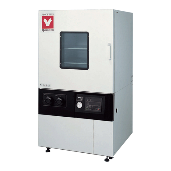
Vacuum Drying Oven
Model DP83C/104C
● Thank you for purchasing "DPC Series Vacuum Drying
Oven" of Yamato Scientific America Co., Ltd.
● To use this unit properly, read this "Instruction Manual"
thoroughly before using this unit. Keep this instruction
manual around this unit for referring at any time.
WARNING: Carefully read and thoroughly understand
the important warning items described in this manual
before using this unit.
Yamato Scientific America Inc.
Third Edition
Advertisement
Table of Contents

Related Manuals for Yamato DPC Series


Summary of Contents for Yamato DPC Series
- Page 1 Vacuum Drying Oven Model DP83C/104C Third Edition ● Thank you for purchasing "DPC Series Vacuum Drying Oven" of Yamato Scientific America Co., Ltd. ● To use this unit properly, read this "Instruction Manual" thoroughly before using this unit. Keep this instruction manual around this unit for referring at any time.
-
Page 2: Table Of Contents
Contents 1. Cautions in using with safety ......................1 Explanation ................1 Table of Illustrated Symbols ............2 Fundamental Matters of "WARNING!" and "CAUTION!" ........3 2. Before using this unit ........................4 Requirements for Installation ............4 3. Description and Function of Each Part ..................9 Main Unit ................ -
Page 3: Cautions In Using With Safety
1. Cautions in using with safety Explanation MEANING OF ILLUSTRATED SYMBOLS Illustrated Symbols Various symbols are used in this safety manual in order to use the unit without danger of injury and damage of the unit. A list of problems caused by ignoring the warnings and improper handling is divided as shown below.Be sure that you understand the warnings and cautions in this manual before operating the unit. -
Page 4: Table Of Illustrated Symbols
1. Cautions in using with safety Table of Illustrated Symbols Warning Warning, Warning, Warning, Warning, Warning, generally high voltage high temperature drive train explosive Caution Caution, Caution, Caution, Caution, Caution, generally electrical shock scald no load heating not to leak Caution, Caution, water only... -
Page 5: Fundamental Matters Of "Warning!" And "Caution
1. Cautions in using with safety Fundamental Matters of "WARNING!" and "CAUTION!" Warning Do not use this unit in an area where there is flammable or explosive gas Never use this unit in an area where there is flammable or explosive gas. This unit is not explosion-proof. An arc may be generated when the power switch is turned on or off, and fire/explosion may result. -
Page 6: Before Using This Unit
2. Before using this unit Requirements for Installation Warning 1. Always ground this unit ・ In order to avoid electric shock caused by electric leakage, be sure to connect the earth wire (the green cable of power cord) to the grounding wire or ground terminal. ・... - Page 7 2. Before using this unit Requirements for Installation Warning 3. Do not use this unit in an area where there is flammable or explosive gas (Refer to page 48 "13. List of Dangerous Substances ".) Never use this unit in an area where there is flammable or explosive gas. This unit is not explosion-proof.
- Page 8 2. Before using this unit Requirements for Installation Warning 4. Do not modify 5. Installation on horizontal surface Modification this unit strictly Set this unit to the flattest place. Setting this prohibited. It may cause a failure. unit on rough or slope place could cause the vibration noise, cause...
- Page 9 2. Before using this unit Requirements for Installation Caution 8. Choose a correct socket Choose a correct power socket that meets the unit’s rated electric capacity. Electric capacity DP83C AC220V 18.5A (not contain vacuum pump current) DP104C 3-phase 480V 17.5A (not contain vacuum pump current) There could be the case that the unit does not run even after turning ON the power.
- Page 10 Model pump ID Ф25mm vacuum rubber hose Vacuum quick-release adapter Clamp (25KF) PD(PX)136 Clamp (40KF) Yamato Ф30mm PD(PX)201 Center ring with O-ring (25KF) Center ring with O-ring (40KF) Vacuum quick-release reducer joint (25-40KF) Stainless steel vacuum rubber hose...
-
Page 11: Description And Function Of Each Part
3. Description and Function of Each Part Main Unit DP83C Door Clasp Observation window Door handle Caution plate Purge valve Power switch (ELB) Pump valve Cable hole Vacuum pressure gauge Caster Operation panel Support foot... - Page 12 3. Description and Function of Each Part Main Unit DP104C Door Observation window Fastening handle Door handle Purge valve Power switch (ELB) Pump valve Cable hole Vacuum pressure gauge Operation panel Support foot...
-
Page 13: Operation Panel
3. Description and Function of Each Part Operation Panel Measured temp. ⑧ ⑭ Heater Alarm ⑨ ℃ Auto stop ⑩ Auto start Set temp. ⑮ Fixed temp. ⑪ Program Over temp. ⑫ protector ⑯ ⑬ ① Start Enter Stop ③ ⑦... -
Page 14: Characters Of The Controller
3. Description and Function of Each Part Characters of the Controller The explanation of VS6 controller characters are as below: Character Identifier Name Purpose Fixed Temperature Used for starting the fixed Setting Mode temperature operation. Temperature Setting Used for setting the temperature. Timer Setting Mode Represents the setting of quick auto AStP... - Page 15 3. Description and Function of Each Part Characters of the Controller Character Identifier Name Purpose Used for inputting the calibration offset Calibration Offset temperature. (Refer to Page 33 "Other Setting Function".) Used for setting temperature for Overheating Prevention overheating prevention device. (Refer Setting to Page 17 "Setting of Overheating Prevention Device ".)
-
Page 16: Operation Method
4. Operation Method Operation Mode and Function List All the operation modes of this unit are as below: Name Description Page Pressing the FIXED TEMP key enters into the fixed temperature operation setting mode. Pressing it again enters into the temperature setting mode. Fixed Temperature The "▲▼"... - Page 17 4. Operation Method Operation Mode and Function List The operation functions of this unit are as below: No. Name Description Page This function is set to be automatically activated (auto Auto overheating reset) when the temperature exceeds the setting prevention function temperature by 12℃.
-
Page 18: Operation Mode, Function Setting Key, And Characters
4. Operation Method Operation Mode, Function Setting Key, and Characters The operation mode and function settings use the operational keys and characters as shown below. -
Page 19: Setting Of Overheating Prevention Device
4. Operation Method Setting of Overheating Prevention Device The unit has the overheating prevention device (manual reset) that consists of independent temperature measurement circuit, CPU, sensor and output circuit (it shares power source, display, and key input with the controller) in addition to the automatic overheating prevention function (auto reset) in the controller. -
Page 20: Fixed Temperature Operation
4. Operation Method Fixed Temperature Operation 1. Turn on the power (turn on the ELB) Fixed temperature The default value is displayed for about 4 seconds after turning on operation procedure the power. The screen then displays the initial setting. The current temperature in furnace, operation mode character and setting temperature of overheating prevention device are displayed on respective screens. -
Page 21: Quick Auto Stop Operation
4. Operation Method Quick Auto Stop Operation Quick auto stop This operation is used to specify the period up to automatic stop, i.e., operation procedure sets the auto stop timer during operation. 1. Set the time up to stop during fixed temperature operation 测... - Page 22 4. Operation Method Quick Auto Stop Operation Change the set temp. If need to change the set temp. during quick auto stop operation, press and set time, confirm FIXED TEMP key to enter the setting mode. the set value If need to change the set time during quick auto stop operation, press TIMER key to enter the setting mode.
-
Page 23: Auto Stop Operation
4. Operation Method Auto Stop Operation Auto stop operation This operation is used to specify the automatic stop time in the fixed procedure temperature operation. 1. Set stop time 测 定 温 度 加热器 故障 ℃ 自动停止 ① Press the TIMER key on the initial screen. 自动开始... - Page 24 4. Operation Method Auto Stop Operation 3. Stop/terminate timer operation 测 定 温 度 加热器 故障 The operation stops automatically at setting time. 自动停止 ℃ 自动开始 设定温度 定值运转 Buzzer continues to sound for about five seconds at operation 程序运转...
-
Page 25: Auto Start Operation
4. Operation Method Auto Start Operation Auto start operation This operation is used to specify the period up to automatic start after procedure power on. 1. Set start time 测 定 温 度 加热器 故障 ℃ 自动停止 ① Press the TIMER key on the initial screen. 自动开始... - Page 26 4. Operation Method Auto Start Operation 3. Stop/terminate timer operation 测 定 温 度 加热器 故障 The operation starts automatically at setting time. ℃ 自动停止 自动开始 设定温度 定值运转 Press the START/STOP key for 1 second to stop or terminate 程序运转...
-
Page 27: Program Operation
4. Operation Method Program Operation Program This operation is used to change the temperature according to the setting operation temperature and time. Temp. △ Start Time △Stop Program types Six patterns of program types maximum can be input. 1 program pattern using 30 steps maximum can ―... - Page 28 4. Operation Method Program Operation DPC type temp. rise The DPC type temp. rise / fall time is as below: / fall time This value is the time needed to reach each temperature (eg. DP83C needs about 15min rising temperature from 100 ℃ to 150 ℃ ). However, the constant temperature time reaching each set temperature needs to be counted separately, so make sure to set proper time to carry on test run.
- Page 29 4. Operation Method Program Operation 3. Select program mode/program pattern 测 定 温 度 加热器 Press the PROGRAM key once. ① 故障 ℃ 自动停止 The measurement temperature display screen displays the 自动开始 设定温度 定值运转 previous program mode. 程序运转 过升防止 Press the PROGRAM key again to display the next program mode. 开始...
- Page 30 4. Operation Method Program Operation The example shown below explains the method of program registration using PrG3. 4. Register program 测 定 温 度 ① Select PrG3 referring to 3 mentioned above.. 加热器 故障 自动停止 ℃ ② Input the number of steps, temperature and time for respective 自动开始...
- Page 31 4. Operation Method Program Operation Make sure to check the setting temperature and time by operating the unit without load before performing actual run with samples. 5. Start program operation 测 定 温 度 加热器 故障 ℃ 自动停止 Press the START/STOP key for about 1 second. The program 自动开始...
-
Page 32: Program Repeat Function
4. Operation Method Program Repeat Function program This section explains how to register the program repeat (repeating repeat function a program pattern) in program operation. This section explains the registration procedure of program using 测 定 温 度 加热器 repeat function in "4. Register program" above. 故障... -
Page 33: Programming Preparation Form
4. Operation Method Programming Preparation Form Please use this form by making copies PrG1 PrG2 PrG3 PAt1 PAt2 PAt3 Register with Date Project Name Programmer Program Pattern... - Page 34 4. Operation Method Programming Preparation Form Please use this form by making copies PrG1 PrG2 PrG3 PAt1 PAt2 PAt3 Register with Date Project Name Programmer Input Value Repeat Function Setting Time (min.) Setting Temperature (℃) To/Times Step 1 : : Step 2 :...
-
Page 35: Other Functions (Calibration)
4. Operation Method Other Functions (Calibration) calibration Calibration offset is a function which corrects the difference between offset function the temperature in furnace and that of controller (sensor temperature) if arises. The function parallel corrects the difference either to the plus or minus side within the whole temperature range of unit. -
Page 36: Other Functions (Lock)
4. Operation Method Other Functions (Lock) This function locks the operation status previously set. The function Use lock function can be set or cancelled by the SUBMENU key. ① Press the SUBMENU key. Select the character" "Lock", which indicates the lock of setting value, using the "▲▼", and then press 测... -
Page 37: Vacuumizing And Air Inflow
4. Operation Method Vacuumizing and air inflow Vacuumizing: PURGE VALVE 1) Turn the purge valve CW to its end (close); 2) Be sure the pump valve is close, turn on the vacuum pump. 3) Turn the pump valve CCW to its end, the exhaust speed is max. here. -
Page 38: Handling Precautions
5. Handling Precautions Warning 1 Substances that cannot be used Never use explosive substances, flammable substances and substances that include explosive or flammable ingredients in this unit. Explosion or fire may occur. (Refer to page47 "13. List of Dangerous Substances ".) 2. - Page 39 5. Handling Precautions Caution 7. Setting of sample Since the withstand load of the attached shelf plate is about 15kg per one plate, do not set heavier sample than 15kg. When setting several sample, set them as dispersed as possible. Too much sample setting could cause the improper control of the temperature. For keeping the proper temperature, keep more than 30% space against whole size of the shelf plate, and set the sample.
-
Page 40: Maintenance Method
6. Maintenance Method Daily Inspection and Maintenance Warning ● Be sure to pull out the power cord except under special circumstances before trying to do inspection and maintenance works. ● Start these works after the device has returned to the normal temperature. ●... -
Page 41: Long Storage And Disposal
7. Long storage and disposal When not using this unit for long term / When disposing Caution Warning When not using this unit for long term When disposing ● Keep out of reach of children. ● Turn off the power and disconnect the power cord. -
Page 42: In The Event Of Failure
8. In the Event of Failure Safety Device and Error Code This unit has an automatic diagnosis function built in the controller and safety devices independent of the controller. The table below shows the cause and the solution method when the safety device operates. -
Page 43: Trouble Shooting
Confirm settings in “Other Functions (Calibration)” on page 32. measurement. ◆ In the case if the error other than listed above occurred, turn off the power switch and primary power source immediately. Contact the shop of your purchase or Yamato Scientific. -
Page 44: After Service And Warranty
9. After Service and Warranty When requesting a repair When requesting a repair If any trouble occurs, immediately stop operation, turn the ELB off, pull out the power plug and contact your dealer or our sales office. Information necessary for requesting a repair ◆Model name of the product ◆Serial number Confirm on the warranty card or the nameplate installed on... -
Page 45: Specification
10. Specification Model DP83C DP104C System Pressure relief and wall heating radiation Temp. control range RT+20℃~200℃ Temp. adjustment ±1℃ (at 200℃) accuracy Temp. rise time Approx. 132min ※1 (RT℃~180℃) Exterior Cold rolled steel plate with coating Insulation materials Glass wool Heater materials Heating plate Heater... - Page 46 10. Specification Model DP83C DP104C Power source AC220V 18.5A 3-phase 480V 17.5A Weight Approx. 450kg Approx. 1000kg Stainless steel SUS304 Shelf plate 2pcs 4pcs Instruction manual, 1 copy for each warranty ※ 1 The performance is under the condition of AC 220V (DP104C is 3-phase 480V) power source, RT 23℃±5℃, humidity 65%RH±5%, unloaded.
-
Page 47: Wiring Diagram
11. Wiring Diagram DP83C AC220V CONT Symbol Part name Symbol Part name Earth Leakage Breaker CONT Control board Terminal block Display board Heater Sensor for control Sensor for overheating AC relay prevention Solid state relay Current transformer... - Page 48 11. Wiring Diagram DP104C AC480V 3 φ4 W 50Hz 3 mm Black 3 mm Black 0.5 mm Black 3P 30A,125mA 480V/220V SSR+ SSR1 SSR2 SSR3 SSR- SSR+ SSR- CONT ~ Heater Control Power Temp. Controller 400WX36 Symbol Part name Symbol Part name Earth Leakage Breaker CONT...
-
Page 49: Replacement Parts Table
12. Replacement Parts Table DP83C/104C Common replacement parts Symbol Part Name Specification Manufacturer Code No. TH1, Sensor T0304.01-16Φ3.2*55*3000 H020401095 Sensor T0304.01-16Φ3.2*55*2000 H020401001 CONT VS6 control board B011401053 VS3, 4 display board VS3,4 B011402007 Signal cable VS1.VS2 300L B011299002 Current transformer URD CTL-6-S-4 B010509001 A011006014... -
Page 50: List Of Dangerous Substances
13. List of Dangerous Substances Never use explosive substances, flammable substances and substances that include explosive or flammable ingredients in this unit. EXPLOSIVE Ethylene glycol dinitrate (nitro glycol), Glycerin trinitrate (nitroglycerine), Cellulose nitrate (nitrocellulose), and other explosive nitrate esters Trinitrobenzene, Trinitrotoluene, Trinitrophenol (picric acid), and other explosive EXPLOSIVE: nitro compounds Acetyl hidroperoxide (peracetic acid), Methyl ethyl ketone peroxide, Benzyl... -
Page 51: Installation Manual
14. Installation Manual ※ Install the product according to the following: (Confirm separately for optional items or special specifications) Serial Installation mgr. Model Date Installation mgr. Judgment number (company name) TOC No. Reference page of the Item Implementation method Judgment operating instruction manual Specifications Included... - Page 52 Responsibility Please follow the instructions in this document when using this unit. Yamato Scientific has no responsibility for the accidents or breakdown of device if it is used with a failure to comply. Never conduct what this document forbids. Unexpected accidents or breakdown may result Note ◆...
Need help?
Do you have a question about the DPC Series and is the answer not in the manual?
Questions and answers