Table of Contents
Advertisement
Quick Links
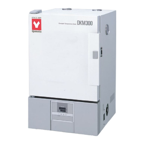
Forced Convection Constant
Temperature Oven
Model: DKM300C/400C/600C
Thank you for purchasing "Forced Convection
Constant Temperature Oven, DKMC Series" of
Yamato Scientific Co., Ltd.
To use this unit properly, read this "Instruction
Manual" thoroughly before using this unit.
Keep this instruction manual around this unit
for referring at anytime.
WARNING!:
Carefully read and thoroughly understand the
important warning items described in this
manual before using this unit.
Yamato Scientific America Inc.
DKM310C/410C/610C
- First Edition -
Advertisement
Table of Contents

Related Manuals for Yamato DKM300C


Summary of Contents for Yamato DKM300C
- Page 1 - First Edition - Thank you for purchasing "Forced Convection Constant Temperature Oven, DKMC Series" of Yamato Scientific Co., Ltd. To use this unit properly, read this "Instruction Manual" thoroughly before using this unit. Keep this instruction manual around this unit for referring at anytime.
-
Page 2: Table Of Contents
Table of Contents 1. Safety precautions............................1 Explanation of pictograms..........................1 List of symbols..............................2 Warning ・ Cautions............................3 2. Before operating the unit..........................4 Precautions when installing the unit......................4 Installation procedures ・ precautions......................7 3. Names and functions of parts......................... 10 Main body............................... -
Page 3: Safety Precautions
1. Safety precautions Explanation of pictograms About pictograms A variety of pictograms are indicated in this operating instruction and on products to assure safe operation. Possible results from improper operation ignoring them are classified as follows. Be sure to fully understand the descriptions below before proceeding to the text. Warning Indicates a situation which may result in death or serious injury (Note 1) -
Page 4: List Of Symbols
1. Safety precautions List of symbols Warning Danger!: Danger!: Danger!: Danger!: Hazard General warnings High voltage High temperature Moving part of explosion Caution Caution for no Caution for water General cautions Electrical shock! Burning! liquid heating! leak! Poisonous For water only material Prohibitions Do not... -
Page 5: Warning ・ Cautions
1. Safety precautions Warning ・ Cautions Warning Never operate the unit in an atmosphere containing flammable or explosive gas Never operate the unit in an atmosphere containing flammable or explosive gas. Otherwise, an explosion or a fire may result since the unit is not explosion-proof. See section “13. -
Page 6: Before Operating The Unit
This might cause unexpected troubles or malfunctions. Weight of the unit are: Model DKM300C/310C:approx 35 kg;Model DKM400C/410C:approx 50 kg;Model DKM600C/610C:approx 65 kg, When lifting the unit for transportation and installation, carefully handle it by at least two people. - Page 7 2. Before operating the unit Precautions when installing the unit 4. Assure sufficient ventilation for the unit. Do not operate the unit when its vent holes on the side and rear panels covered or blocked. Internal temperature of the unit will rise degrading the performance and an accident, a malfunction or a fire may result.
- Page 8 7. Be sure to connect the power plug to the dedicated power distribution panel or a wall outlet. Choose a correct power distribution board or receptacle that meets the unit’s rated electric capacity. Electrical capacity: DKM300C AC115V 7.5A DKM310C AC220V 4.5A...
-
Page 9: Installation Procedures ・ Precautions
2. Before operating the unit Installation procedures ・ precautions Select an installation site. ・ Make sure that all of four legs are securely on a flat surface. Install shelf boards. ・ The lowest shelf board has been secured with screws at the time of shipping from the factory. - Page 10 2. Before operating the unit Installation procedures ・ precautions ・ Put samples with spaces between them. Too many samples may prevent proper temperature control. To assure proper temperature control, put samples with a space at least 30% of the shelf board area. Make at least 30% of space Do not put a sample on the bottom of the internal bath.
- Page 11 2. Before operating the unit Installation procedures ・ precautions About two-tier stacking ・ Use the dedicated optional parts to stack units in two tiers. Contact you dealer or the nearest sales office for the dedicated optional part. Before using the unit for the first time ・...
-
Page 12: Names And Functions Of Parts
3. Names and functions of parts Main body DKM300C/400C/600C/310C/410C/610C Front panel Door Cable port Rating plate Handle Standalone overheat protection device (hydraulic) Power switch (MCB) Operation panel Rear panel Exhaust port Power cord... -
Page 13: Operation Panel
3. Names and functions of parts Operation panel M EASURED TEM P. ⑥ ⑤ ℃ ⑦ ④ HEATER SET TEM P. ③ ① RU N TI M ER STO P SUB M ENU ② Name Operation/action RUN/STOP key Used for starting/stopping operation. ①... -
Page 14: Explanation Of Characters
3. Names and functions of parts Explanation of characters Characters on the controller are explained in this section. Characters Identifier Name Application AStP Auto stop setting Used for setting auto stop operation AStr Auto start setting Used for setting auto start operation Displayed when timer operation has Time up ended. -
Page 15: Operating Procedures
4. Operating procedures List of operation modes and functions Operation modes of the unit are as shown below: Name Description Page № Turning the MCB on to enter the operation setting mode. Proceed to temperature setting that uses ▼▲ keys. Fixed temperature Pressing the RUN/STOP key longer starts operation, P.17... - Page 16 4. Operating procedures List of operation modes and functions Functions of the unit are as shown below: Name Description Page № Automatic overheat prevention function: This function is linked to the unit set temperature and has been set to so that it is automatically activated (returned automatically) at a temperature 12℃...
-
Page 17: Operation Mode ・ Function Setting Keys And Characters
4. Operating procedures Operation mode ・ function setting keys and characters Key operations and characters in the diagram below are used for operation mode and function settings. -
Page 18: Operating Procedures (Settings For Overheat Prevention Device)
4. Operating procedures Operating procedures (settings for overheat prevention device) As a safety measure for preventing overheat, a hydraulic overheat prevention device (manual return) is installed. Temperature setting range and functions The temperature setting range for the standalone overheat prevention device is “50℃~320℃.” When the temperature in the bath keeps rising beyond the controller set temperature and reaches the set temperature of the overheat prevention device, the heater circuit trips and the controller operation is shut off. -
Page 19: Operating Procedures (Fixed Temperature Operation)
4. Operating procedures Operating procedures (fixed temperature operation) How to start fixed 1. Turn the MCB ON. (Turn the MCB to “ON.”) temperature operation When the MCB is turned ON, the initial values will be displayed for about four seconds, then the initial screen will appear and the current bath temperature and the previous set temperature are displayed on each of the indicators. -
Page 20: Operating Procedures (Quick Auto Stop Operation)
4. Operating procedures Operating procedures (quick auto stop operation) Used when you want to “stop fixed temperature operation being performed automatically in several hours. Quick auto stop operation is a function to enable auto stop timer setting during operation. Procedures for quick auto 1. - Page 21 4. Operating procedures Operating procedures (quick auto stop operation) When you want to correct set When you want to change settings, press the ▼▲ keys on the current screen to enter the setting mode where you can temperature or set time, or change settings.
-
Page 22: Operating Procedures (Auto Stop Operation)
4. Operating procedures Operating procedures (auto stop operation) This mode automatically stops fixed temperature operation after a certain time from its start set with the timer. Procedures for auto stop 1. Setting a stop time After confirming the temperature you want is set, press operation the TIMER key to display characters AStP the MEASURED TEMP. - Page 23 4. Operating procedures Operating procedures (auto stop operation) When you want to correct set When you want to change settings, press the ▼▲ keys on the current screen to enter the setting mode where you can temperature or set time, or change settings.
-
Page 24: Operating Procedures (Auto Start Operation)
4. Operating procedures Operating procedures (auto start operation) This mode automatically starts fixed temperature operation after a certain time from its start set with the timer. However, operation does not stop automatically but needs to be stopped manually. Procedures for auto start 1. - Page 25 4. Operating procedures Operating procedures (auto start operation) When you want to When you want to change the set temperature during timer counting, press the ▼ ▲ keys during that status to switch the SET TEMP. correct set screen to the set temperature input mode, which blinks to enable temperature or set change of the set temperature with the ▼▲...
-
Page 26: Useful Functions (Calibration Offset Function)
4. Operating procedures Useful functions (calibration offset function) Using the calibration offset Calibration offset function compensates any differences between the target temperature in the bath and the control function temperature of the controller (sensor temperature.) The function can compensate in parallel to either plus or minus side for the whole temperature band of the unit. -
Page 27: Useful Function (Setting Lock Function)
4. Operating procedures Useful function (setting lock function) Using the lock function This function locks the set operation status. The temperature is set at “off” on shipping from the factory. ① Press the TIMER key (SUB MENU key) long to enter the sub menu mode. -
Page 28: Useful Function (Power Outage Compensation Function)
4. Operating procedures Useful function (power outage compensation function) Using the power outage The power outage compensation function returns the main compensation function unit operation to the resume status after recovery from power outage, or keeps the current stop status. The function is set at “on”... -
Page 29: Cautions On Handling
2. Ban on use/countermeasures when an error occurs If smoke is emerges on the unit or an odd odor is felt, immediately turn the MCB on the main unit off, turn the power supply off and contact your dealer or a Yamato sales office for inspection. - Page 30 5. Cautions on handling Caution 1. Do not step on the unit. Do not step on the unit. Otherwise, the unit may trip over or be damaged resulting a personal injury or a malfunction. 2. Do not put or drop an object on the unit. 2.Do not put or drop an object on the unit.
- Page 31 5. Cautions on handling Caution 9. About installation of shelf boards and samples Install shelf boards and samples correctly according to “Installation procedures ・ precautions” on page 7. Otherwise, an accident or a malfunction may result not only to prevent the unit to operate at its maximum performance. 10.
-
Page 32: Maintenance Procedures
6. Maintenance procedures Daily inspection/maintenance Be sure to perform daily inspection and maintenance to assure reliable operation of the unit. Warning Be sure to pull out the power cord unless necessary before trying to do inspection and ● maintenance works. Start these works after the device has returned to the normal temperature. -
Page 33: When The Unit Is Not To Be Used For A Long Time Or When Disposing
7. When the unit is not to be used for a long time or when disposing When the unit is not to be used for a long time or when disposing Caution Warning When the unit is not going to be used for a long When disposing the unit time ●... -
Page 34: Troubleshooting
8. Troubleshooting Safety device and error codes The unit has the self diagnostic function with a controller and a separate safety device. Table below shows possible causes and measures when the safety device is triggered. [Error codes] When a functional or mechanical abnormality occurs, an error code will be displayed on the control panel. -
Page 35: When A Malfunction Is Suspected
8. Troubleshooting When a malfunction is suspected If any of the symptoms below occurs Symptom Check the power cord is connected to the power supply ● Check if Turning the MCB to on will not securely. activate the unit. ● Check if power outage is occurring. -
Page 36: After Sales Service And Warranty
9. After sales service and warranty When requesting a repair When requesting a repair If any trouble occurs, immediately stop operation, turn the MCB off, pull out the power plug and contact your dealer or our sales office. Information necessary for requesting a repair ●Model name of the product Refer to the warranty card or the nameplate on the unit. -
Page 37: Specifications
10. Specifications Model DKM300C DKM310C DKM400C DKM410 DKM600 DKM610 Operating Room temperature +10℃~260℃ temperature range Temperature control ±1℃(setting: 210℃) precision Temperature ±2.5℃(setting: 210℃) distribution precision Temperature rise time Approx. 90 minutes (room temperature ~260℃) Cable port ID 30 mm x 1 (right side) -
Page 38: Wiring Diagram
11. Wiring diagram DKM300C/400C/600C X2-1 X2-2 AC220V AC115V CONT Symbol Part name Symbol Part name Circuit Breaker Solid state relay Thermostat Terminal block (Standalone overheat prevention device) Heater Temperature sensor (K) X1, X2 Relay CONT Planar board Fan motor Display circuit board... - Page 39 11. Wiring diagram DKM310C/410C/610C X2-1 X2-2 AC220V CONT Symbol Part name Symbol Part name Circuit Breaker Solid state relay Thermostat Terminal block (Standalone overheat prevention device) Heater Temperature sensor (K) X1, X2 Relay CONT Planar board Fan motor Display circuit board...
-
Page 40: List Of Replacement Parts
Motor 220V,10W,CCW Yamato Scientific A011603004 Power cord kit 3×2.08mm2 Yamato Scientific A011210002 DKM310C SUS pipe heater 220V 0.8kW Yamato Scientific SJA04170 Heater DKM410C SUS pipe heater 220V 1.2kW Yamato Scientific SJA04171 DKM610C SUS pipe heater 220V 1.34kW Yamato Scientific SJA04172... -
Page 41: List Of Dangerous Materials
13. List of dangerous materials Never use an explosive material, a flammable material or a material containing them for this device. ①Nitro glycol, glycerin trinitrate, cellulose nitrate and other explosive nitrate esters ②Trinitrobenzen, trinitrotoluene, picric acid and other explosive nitro compounds ③... -
Page 42: Standard Installation Manual
14. Standard installation manual *Install the product according to the following: (Confirm separately for optional items or special specifications) Installation mgr. Judg Model Serial number Date Installation mgr. (company name) ment TOC No. Reference page of the Judg Item Implementation method №... - Page 43 Responsibility Please follow the instructions in this document when using this unit. Yamato Scientific has no responsibility for the accidents or breakdown of device if it is used with a failure to comply. Never conduct what this document forbids. Unexpected accidents or breakdown may result in.
Need help?
Do you have a question about the DKM300C and is the answer not in the manual?
Questions and answers