Table of Contents
Advertisement
Quick Links
Clean Oven
Instruction Manual
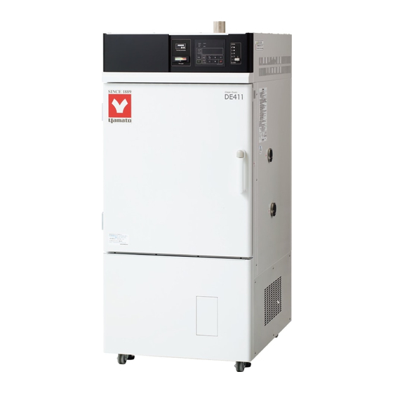
● Thank you for choosing DE411/611 and DT411/611
series Clean Ovens from Yamato Scientific Co., Ltd.
● This
product
applications. For laboratory drying and sterilization
use only.
● For proper equipment operation, please read this
instruction manual thoroughly before use. Always
keep equipment documentation safe and close at
hand for convenient future reference.
Warning
: Read instruction manual warnings
Yamato Scientific America Inc.
Santa Clara,CA
DE411/611
DT411/611
First Edition
is
not
intended
and cautions carefully and
completely before proceeding.
.
for
medical
Printed on recycled paper
Advertisement
Table of Contents
Troubleshooting

Subscribe to Our Youtube Channel
Related Manuals for Yamato DE411


Summary of Contents for Yamato DE411
- Page 1 Clean Oven DE411/611 DT411/611 Instruction Manual First Edition ● Thank you for choosing DE411/611 and DT411/611 series Clean Ovens from Yamato Scientific Co., Ltd. ● This product intended medical applications. For laboratory drying and sterilization use only. ● For proper equipment operation, please read this instruction manual thoroughly before use.
-
Page 2: Table Of Contents
8. TROUBLESHOOTING ......................54 Error Codes ............................54 Troubleshooting Guide ........................56 9. SERVICE AND REPAIR ......................57 10. SPECIFICATIONS ........................58 11. ACCESSORY OPTIONS ......................60 Accessory Item List ........................... 60 12. WIRING DIAGRAM......................... 62 DE411/611 DT411/611 ........................62... - Page 3 Wiring Diagram Glossary ........................63 13. HAZARDOUS SUBSTANCES LIST ..................64 14. SETUP CHECKLIST ....................... 65 APPENDIX 1 ..........................66 Program Planning Worksheet ......................66...
-
Page 4: Safety Precautions
1. SAFETY PRECAUTIONS Explanation of Symbols A Word Regarding Symbols Various symbols are provided throughout this text and on equipment to ensure safe operation. Failure to comprehend the operational hazards and risks associated with these symbols may lead to adverse results as explained below. -
Page 5: Symbol Glossary
1. SAFETY PRECAUTIONS Symbol Glossary Warning Danger!: High Danger!: Danger!: Moving Danger!: General Warning Voltage Extremely Hot Parts Blast Hazard Caution Caution: Do Not Caution: Caution: Caution: May General Caution Heat Without Shock Hazard! Burn Hazard! Leak Water! Water! Caution: Caution: Toxic Water Only Chemicals... -
Page 6: Warnings And Cautions
1. SAFETY PRECAUTIONS Warnings and Cautions Warning NEVER operate equipment near combustible gases/fumes. Do not install or operate DE/DT series unit near flammable or explosive gases/fumes. Unit is NOT fire or blast resistant. Negligent use could cause a fire/explosion. See “List of Hazardous Substances” (P.64). ALWAYS ground equipment. -
Page 7: Pre-Operation Procedures
2. PRE-OPERATION PROCEDURES Installation Precautions & Procedures 1. Choose an appropriate installation site. DO NOT install unit: ・where flammable or corrosive gases/fumes will be generated. ・where ambient temperature will exceed 35ºC, will fall below 5ºC or will fluctuate. ・in excessively humid or dusty locations. ・where there is constant vibration. - Page 8 See “List of Hazardous Substances” (P.64). 10. Connect to a proper power supply terminal. Connect power cable to a suitable facility outlet or terminal, according to the following electrical requirements. Power DE411 AC220V 3 phase 50/60Hz 7.0 A requirements: DE611 AC220V 3 phase 50/60Hz 10.0A...
- Page 9 Turn off main power switch (ELB) immediately and disconnect from facility terminal or outlet, if power cable becomes partially severed or damaged in any way. Failure to do so may result in fire or electric shock. Contact a local dealer or Yamato sales office for assistance in replacing power cable if it is damaged.
- Page 10 2. PRE-OPERATION PROCEDURES Installation Precautions & Procedures 14. DO NOT disassemble or modify. Attempting to disassemble or modifiy this unit in any way may result in malfunction, fire or electric shock. 15. Chamber rack installation and sample placement. Install rack guides in desired position inside chamber before initial use. Placing samples directly on bottom chamber surface may overheat samples, cause spills or lead to other mishaps.
-
Page 11: Component Names & Functions
3. COMPONENT NAMES & FUNCTIONS Main Unit Exterior view Exhaust Port Control Panel Heat Vent Rating & Production Label Door Handle Cable Port Door Intake Port Flow Meter Blank for N Gas Option Heat Vent Louver Leveling Foot Main Power Switch (ELB) HEPA Filter Terminal Block Blank for Access Panel... -
Page 12: Interior Structure
3. COMPONENT NAMES & FUNCTIONS Interior Structure Exhaust Port Temp Control Sensor Rack Support Chamber Rack HEPA Filter Support Post Heater Sirocco Fan Fan Motor Caster Leveling Foot... -
Page 13: Control Panel
3. COMPONENT NAMES & FUNCTIONS Control Panel Name Description Upper Display Readout for chamber temperature, error code, etc. Lower Display Readout for temperature setting, clock, timer, etc Function Indicator Lamps Illuminates (one or more) to show which function is currently running or active Mode Indicator Lamps Illuminates (one at a time) to show which mode is currently running. -
Page 14: Operation Procedure
4. OPERATION PROCEDURE Prior Confirmation 1. Check power supply and ground wire. Confirm unit power cable is connected to a proper power source and grounded. 2. Check main power switch (ELB). Confirm that ELB functions properly. See “Maintenance Procedures” (P.52). Check ELB performance once a month or before extended perpetual operation. -
Page 15: Setting Date & Time
5 years. Replacing battery within the 5-year lifespan is recommended. Contact a local dealer or Yamato sales office to request a replacement battery. If unit has program data in memory, backup these settings before replacing backup battery. See P.42 of this manual for details. -
Page 16: Buzzer Function Selection
4. OPERATION PROCEDURE Setting Date & Time 3 Set the date. 1) Press 2) Set the current year using and press 3) Set month/date using and press Press to move cursor position. 4 Set clock. 1) Press 2) Press and set clock using Press ... - Page 17 4. OPERATION PROCEDURE Mode & Function Flow...
-
Page 18: Constant Temperature Operation
3 Set temperature. 1) Press . Changeable digits flash in lower display. 2) Change digit positions using increase or decrease value using Operating temperature ranges: DE411/611: 0~260ºC DT411/611: 0~360ºC 3) Press when temperature setting has been entered. - Page 19 4. OPERATION PROCEDURE Constant Temperature Operation 4 Start operation. Press to start operation. OPERATE and HEATER lamps light and temperature begins building. Lower display in heat build phase: Lower display in temperature stabilization: Lower display in cooling phase: 5 Pause/stop operation Press to manually terminate operation.
- Page 20 4. OPERATION PROCEDURE Constant Temperature + Quick Auto Stop Operation 6 Set timer The quick auto stop function is used to automatically stop constant temperature operation at a certain time (by clock) or after a desired duration (by timer). (decided during operation).
- Page 21 4. OPERATION PROCEDURE Constant Temperature + Quick Auto Stop Operation 6) When timer runs out or when stop time is reached operation stops, lower display reads 7) Press to clear from display. When operation stops and is cleared, start screen is restored.
-
Page 22: Auto Stop Operation
4. OPERATION PROCEDURE Auto Stop Operation AUTO STOP (Automatic Stop) utilizes timer or clock to automatically stop an operation. Operation must be started manually. See below. Auto stop mode set to timer: When auto stop mode is set to the timer, unit enters a wait period, and remains “waiting”... - Page 23 4. OPERATION PROCEDURE Auto Stop Operation 2 Select auto stop mode Press key repeatedly until both FIXED TEMP and AUTO STOP lamps light. Fixed Temperature mode is factory default. Once mode has been changed, the last mode run will be selected on subsequent startups. 3 Set temperature and stop timer/clock 1) Press 2) Select stop TIME or CLOCK (lamp in upper-left...
- Page 24 4. OPERATION PROCEDURE Auto Stop Operation 4 Start operation Press to start operation. OPERATE and HEATER lamps light and temperature begins building. Press at any time during operation to monitor remaining time in the lower display. emaining time display (timer): ...
-
Page 25: Auto Start Operation
4. OPERATION PROCEDURE Auto Start Operation AUTO START (Automatic Start) mode utilizes timer or clock to automatically begin an operation. Operation must be stopped manually. Timer launch Operation start (automatic) SV: Temperature setting, t: Auto start time (time) Set Auto Start mode 1 Turn on power. - Page 26 4. OPERATION PROCEDURE Auto Start Operation Example 1. Auto Start mode set to timer: Operation automatically begins 35 hours and 30 minutes after is pressed. Example 2. Auto Start mode set to clock: Press and operation begins automatically at 15:00 (3:00PM). Start operation 1) Press to enter standby mode (wait) until...
- Page 27 4. OPERATION PROCEDURE Auto Start Operation 3) When start timer runs out or when clock and start time agree, the OPERATE lamp changes from flashing to lighted; HEATER lamp lights and temperature begins building. The quick auto stop function is inoperable during auto start mode.
-
Page 28: Programmed Operation
4. OPERATION PROCEDURE Programmed Operation PROGRAM mode runs a combination of times and temperatures in a series of programmed steps as one operation. See below. Running programs 1 Turn power ON Turn main power switch ON (|) (idle). Press and hold to turn control panel power on (standby). - Page 29 4. OPERATION PROCEDURE Programmed Operation 3 Select program number Press . The program number in lower display will begin flashing. Select desired program number using and press 4 Start programmed operation Press to start programmed operation. Do not attempt to run a cycle if has not been set at the end step in a program.
- Page 30 4. OPERATION PROCEDURE Programmed Operation 5 Operation end 1) When selected program cycle ends, lower display shows and operation stops. 2) Clear by pressing Initial screen is restored. Fan continues running regardless of whether operation is stopped. Press and hold to turn off control panel and stop fan.
- Page 31 4. OPERATION PROCEDURE Programming Procedure Sample program In this example, there are 8 steps in program pattern 2. Steps from 4 to 7 are repeated 5 times and the program ends with step 8. Note: Steps 4 to 7 are run a total of 6 times. Repeat Pattern No Step...
- Page 32 4. OPERATION PROCEDURE Programming Procedure The following outlines the procedure for building the example program on P.28: (This procedure assumes unit is set to factory defaults) Screen status Procedure flashes. III. PROGRAM lamp flashes. - “ ” appearing in upper display indicates that steps for selected program have already been entered and finalized.
- Page 33 4. OPERATION PROCEDURE Programming Procedure Enter program pattern - TEMP flashes in bottom left of lower display. Enter (°C). - Last “ ” in “ ” flashes. Enter “ ” (0 hours and 0 minutes - default). - TIME flashes in bottom left of lower display.
- Page 34 4. OPERATION PROCEDURE Programming Procedure Set “ ” setting to (default). (to program next step, set to ; to enter current step as final, set to All program lamps flash. 1-10 Press and hold setting complete. Input program pattern STEP02 Enter parameters for 2 ~ 6 in the STEPS...
- Page 35 4. OPERATION PROCEDURE Programming Procedure Enter “ ” (repeat begins at Enter “ ” (repeats steps five times) Repeat count may be set between 1 and 99 or to indefinite setting, “ ” (infinity). Turn wait function “ ”. WAIT lamp flashes.
- Page 36 4. OPERATION PROCEDURE Programming Procedure Enter “ ” (0 hours, 30 minutes) Entering “ ” on final step makes time setting indefinite (must be stopped manually). Enter “ ” (No repeat destination) Enter “ ” (No repeats) Set wait function to Wait lamp flashes.
-
Page 37: Copying & Deleting Programs
4. OPERATION PROCEDURE Copying & Deleting Programs Copying programs Press repeatedly until appears, flashing in lower display. Press shows with the “ ” flashing in lower display. Enter the program number to be copied using and press “ ” flashes in upper display. while the lowest available program number (i.e. - Page 38 4. OPERATION PROCEDURE Copying & Deleting Programs Deleting programs Press repeatedly until shows, flashing in lower display. Press shows with the “ ” flashing in lower display. Select a pattern number to delete using , or select (ALL) using then press and hold When “...
-
Page 39: Wait Function
4. OPERATION PROCEDURE Wait Function When the wait function is set to ON, the system “waits”, without counting down time, until chamber temperature (reading) is within the deviation zone of between -3°C and +6°C of the temperature setting. When time is set to 0 minutes, the system will build heat at full power to reach setting as quickly as possible. When time is set longer than system normally takes to heat or cool to selected temperature, unit will automatically control heating and cooling so that temperature setting is reached (staying within the deviation range) at the time setting. -
Page 40: Keypad Lock Function
4. OPERATION PROCEDURE Keypad Lock Function Set keypad lock. 1 Turn control power off (idle) Turn main power switch ON (|). Lower display shows current time. If unit is in standby, press and hold to turn control panel power off (idle). 2 Enter password 1) Press and hold shows in lower display while... -
Page 41: Calibration Offset Function
The -2°C calibration in the example above is applied over the entire temperature setting range (DE411/611: 0~260°C, DT411/611: 0~360°C). Note that offset values may change slightly depending on sample/specimen arrangement in the chamber and/or temperature setting. -
Page 42: Recovery Function
4. OPERATION PROCEDURE Recovery Function Select recovery mode for the event of a power failure. 1 Turn control panel off (idle) Turn main power switch ON (|). Lower display shows the current time. If unit is in standby, press and hold to turn control panel power off (idle). -
Page 43: Co 2 Emissions & Power Consumption Settings
4. OPERATION PROCEDURE Emissions & Power Consumption Settings Setting CO conversion factor & resetting total CO emissions/power consumption. 1 Turn control panel power off Turn main power switch ON (|). Lower screen shows current time. If unit is in standby, press and hold to turn control panel power off (idle). - Page 44 4. OPERATION PROCEDURE Emissions & Power Consumption Settings :CO emission factor. The factory default setting of (0.000550t /kWh) reflects the Environmental Ministry Press Release on 6 November 6, 2013. Applicable value varies by utility company. Contact the servicing utility authority to confirm what value should be used.
-
Page 45: Data Backup, Data Recovery & Reset
4. OPERATION PROCEDURE Data Backup, Data Recovery & Reset Back up data, recover data from backup or reset data to factory default. 1 Turn control panel off Turn main power switch ON (|). Lower screen shows the current time. If unit is in standby, press and hold to turn control panel power off (idle). -
Page 46: Monitoring Data
4. OPERATION PROCEDURE Monitoring Data Current power consumption, accumulated hours of operation, etc. may be viewed by using the data monitoring feature. Setting information shown in upper display cannot be modified. 1 Applicable value shows in upper Monitoring items may be viewed in standby or while display operation is in progress. - Page 47 OPERATION PROCEDURE Monitoring Data Heater Output Heater output shows heater power output ratio in a percentage of rated capacity. Output is controlled by a PID operation value between 100 and 0% until temperature setting is reached. Example If upper display shows , ouput is at 45.6% of rated heater capacity.
-
Page 48: Independent Overheat Prevention Device
Likewise, it is NOT intended for protection against accident or injury resulting from the negligent use of explosives and flammables. Factory defaults and setting ranges are shown below: Model Factory default setting Setting range 0℃~300ºC DE411 280ºC 0℃~300ºC DE611 280ºC 0℃~400ºC DT411 380ºC... -
Page 49: Handling Precautions
In the event that a foreign object accidentally falls inside, turn off main power (ELB) immediately, disconnect power cable and contact a local dealer, or Yamato sales office for assistance. Continuing to operate unit without removing object may cause fire or electric shock resulting in serious injury or death. -
Page 50: Caution
ALWAYS run equipment within specified temperature range. Working temperature range is room temperature +15°C~260°C (DE411/611) and +15°C~ 360°C (DT411/611). Never attempt to operate unit outside of specification range. Equipment malfunction or damage may result. - Page 51 Table 5.1. Do not process test samples which contain any of the substances shown in this table. For further assistance, contact a Yamato sales office or dealer. Table 5.1 - Substances that are harmful to chamber door seal...
- Page 52 5. HANDLING PRECAUTIONS Caution Material Silicon Rubber Fluoro-rubber Classification Ether Diethyl Ether, Dibutyl Ether, Diethyl Ether, Isopropyl Ether, Ethylene Oxide, Dioxane, Dibutyl Ether, Dibenzyl Ether, Epichlorohydrin, Tetrahydrofuran Ethylene Oxide、Dioxane, Epichlorohydrin, Furfural, Tetrahydrofuran Alcohol Amyl alcohol Multiple Alcohol Cellosolve Acetate, Butyl Cellosolve, Derivative Triacetin Acetic Anhydride, Oleic Acid,...
- Page 53 5. HANDLING PRECAUTIONS Caution 11. Temperature control. The temperature sensor for this unit is installed on the inside wall of the chamber and used to control chamber temperature. Chamber temperature reading, as detected by the sensor, may not always agree with the temperature of test specimens. More often than not, chamber and test sample temperatures will differ largely immediately after opening or closing chamber door.
- Page 54 5. HANDLING PRECAUTIONS Caution 17. Cable port precaution. Whenever a manual temperature gauging sensor or probe is inserted through the cable port, close the port cover as fully as possible and completely seal any gaps with heat-resistant insulation or sealant. If the seal is inadequate, temperature characteristics or other performance properties will be degraded and inaccurate.
-
Page 55: Maintenance Procedures
HEPA filter sooner, rather than later, is therefore recommended ・ Utmost care must be taken when replacing HEPA filter and should be done by Yamato or other certified technician. ◆Contact local Yamato dealer or Yamato Customer Service Center for service or questions. -
Page 56: Storage And Disposal
Dispose of or recycle this unit in a responsible and environmentally friendly manner. Yamato Scientific Co., Ltd. strongly recommends disassembling unit, as far as is possible, in order to separate parts and recycle them in contribution to preserving the global environment. -
Page 57: Troubleshooting
8. TROUBLESHOOTING Error Codes All possible error codes are shown in Table 8.1 below. On DE/DT series units, operation stops and a sounding alarm accompanies occurring errors. Pressing any key (except ) will pause the alarm. After three minutes alarm will sound again. Upper display shows error code and error source source appears in lower display. - Page 58 8. TROUBLESHOOTING Error Codes Error Error Code Name Causes and their solutions Display Turn ELB OFF, then back ON (reset) and confirm whether backup battery capacity is decreased or is dead. RAM Failure, Replace backup battery backup battery capacity reduced or dead If error cannot be cleared by ELB reset or battery replacement, Contact original dealer of purchase...
-
Page 59: Troubleshooting Guide
8. TROUBLESHOOTING Troubleshooting Guide Table 8.2 - Troubleshooting Guide Symptom Possible Causes Possible Solutions ・ Check connection to power Unit does not turn ・ No power from power supply supply and confirm power supply on/operate when main ・ ELB failure voltage. -
Page 60: Service And Repair
9. SERVICE AND REPAIR Requests for Repair When a problem occurs, terminate operation immediately, turn off main power switch (ELB) and disconnect power cable. Contact original dealer of purchase. The following information is required for all repairs. ● Model name ●... -
Page 61: Specifications
10. SPECIFICATIONS Product Clean oven Model DE411 DE611 DT411 DT611 System Forced air circulation and ventilation External temperature range 5℃~35℃ Triple phase Triple phase Triple phase Triple phase 220V AC 7A 220V AC10A 220V AC 10A 220V AC 14A Power supply Common to 50/60Hz, operating voltage range:±10%... - Page 62 10. SPECIFICATIONS Model DE411 DE611 DT411 DT611 Constant temperature operation Programmed operation (Maximum 99 steps, up to 99 patterns, repeat operation Operation modes function) Duration/time select operation function (auto start/auto stop/quick auto stop, program operation) Variable fan speed Accumulated on time, operation time function (up to 65,535 hours); calibration Additional offset;...
-
Page 63: Accessory Options
11. ACCESSORY OPTIONS Accessory Item List Clean Ovens DE411/61, DT411/611 are compatible with a wide variety of available options as shown in Tables 11.1. and 11.2. Options listed in Table 11.2 are required to be installed at theYamato manufacturing facility. - Page 64 Duct 212927 ODT18 DE/DT611 external fan unit not included. Hi-performance filter maintains 212954 ODT68 DE411 clean level class 100 in all heating conditions (stabilization, increase, Hi-performance HEPA filter decrease). 212955 ODT70 DE611 Max resistance temp: 200℃.
-
Page 65: Wiring Diagram
12. WIRING DIAGRAM DE411/611 DT411/611... -
Page 66: Wiring Diagram Glossary
12. WIRING DIAGRAM Wiring Diagram Glossary Symbol Component Symbol Component ELB1 Earth Leakage Breaker (ELB) Photo coupler Wiring terminal 1 Door switch Wiring terminal 2 Spark eliminator Main relay Fan motor Thermal relay Type V planar board Phase reversal relay Type V display board Independent Overheat Prevention SSR1, 2... -
Page 67: Hazardous Substances List
13. HAZARDOUS SUBSTANCES LIST Never attempt to process explosives, flammables or any items which contain explosives or flammables. ①Nitroglycol, Glycerine trinitrate, Cellulose Nitrate and other explosive nitrate esters ②Trinitrobenzen, Trinitrotoluene, Picric Acid and other explosive nitro compounds ③Acetyl Hydroperoxide, Methyl Ethyl Ketone Peroxide, Benzoyl Peroxide and other organic peroxides ④Metallic Azide, including Sodium Azide, etc. -
Page 68: Setup Checklist
14. SETUP CHECKLIST Setup DE/DT series units using the following procedure: Installed by (company or Installation approved Assessed Model Serial number Installation Date personnel) Assessed Item Procedure Section & Reference Page Specifications Verify inlcuded accessories against Accessories 10. Specifications accessories column. ・Check site visually. -
Page 69: Program Planning Worksheet
APPENDIX 1 Program Planning Worksheet Control № Preparation Model name (Y) (M) (D) date Prepared by Program number Temperature setting Program pattern (℃) (℃) Step № Repeat Program Repetition *Damper Temperature Step Time Wait *Event Setting Dstn Count Speed Aperture TEMP WAIT EVENT... - Page 70 Always operate equipment in strict compliance to the handling and operation procedures set forth by this instruction manual. Yamato Scientific Co., Ltd. assumes no responsibility for malfunction, damage, injury or death resulting from negligent equipment use. Never attempt to disassemble, repair or perform any procedure on DE/DT series units which are not expressly mandated by this manual.
Need help?
Do you have a question about the DE411 and is the answer not in the manual?
Questions and answers