Table of Contents
Advertisement
Quick Links
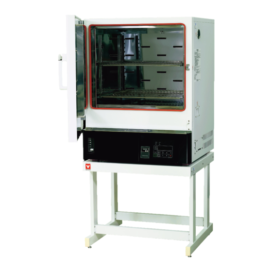
Variable wind-speed constant-temperature
Instruction Manual
● Thank you for purchasing "Variable wind-speed
constant-temperature drying oven (2in1 oven)DNF301/
DNF401/411/ DNF601/611" of Yamato Scientific Co., Ltd.
● In order to use this Equipment properly, please read
this Instruction Manual and Warranty Card thoroughly
before use.
Equipment so that you can refer to them any time.
Warning
Yamato Scientific America Inc.
drying oven
(2in1 oven)
DNF301
DNF401/411
DNF601/611
First Edition
Keep them in safe place close to this
: Please read the important warning
notes in this Manual carefully and
thoroughly, and get the good
understanding of their contents
before using this Equipment.
Santa Clara,CA
Ovens Available From:
For Information and to Order
Contact Us At:
323-770-0634 800-574-2748
Email: sales@LRE.com Web Site:
www.LRE.com
Printed on recycled paper
Advertisement
Table of Contents

Subscribe to Our Youtube Channel
Related Manuals for Yamato DNF301 DNF401


Summary of Contents for Yamato DNF301 DNF401
- Page 1 First Edition ● Thank you for purchasing “Variable wind-speed constant-temperature drying oven (2in1 oven)DNF301/ DNF401/411/ DNF601/611” of Yamato Scientific Co., Ltd. ● In order to use this Equipment properly, please read this Instruction Manual and Warranty Card thoroughly before use.
-
Page 2: Table Of Contents
Contents 1. Safety Precautions ..............1 Explanation of symbols ..............1 List of symbols .................2 Residual risk map ..............3 Warnings・Cautions..............4 List of residual risks ..............5 2. Before operating the Equipment ............ 6 Precautions when installing the Equipment ..........6 3. Names and functions of each part ..........11 External view .................11 3. - Page 3 Matters to consider when scrapping the Equipment ........63 8. When a trouble occurs ............64 Message error table ..............64 Troubleshooting ..............66 9. After sales service and warranty ..........67 Request to repair parts ..............67 10. Specifications ..............68 Specifications ................68 11.
-
Page 4: Safety Precautions
1. Safety Precautions Explanation of symbols About symbols Various symbols are provided in this Instruction Manual and on the product to ensure safe operation. Improper handling of this Equipment without understanding their contents will lead to the results classified below. Be sure to fully understand the description of symbols below before proceeding to the text of this Manual. -
Page 5: List Of Symbols
1. Safety Precautions List of symbols Warning General Danger!: High Danger!: High Danger!: Moving Danger!: Warnings Voltage Temperature Part Explosion Hazard Caution Caution: Heating Caution: Caution: Water General Cautions Caution: Burns! Container without Electrical Shock! Leak! water! Caution: For Caution: Toxic water only Chemicals Prohibitions... -
Page 6: Residual Risk Map
1. Safety Precautions Residual risk map The figure shows the position to apply the caution seal. The numbers shown in the figure represent the numbers of residual risk relevant to the location concerned, which are provided in the List of Residual Risks for this product. For details of individual residual risks, see the List of Residual Risks. -
Page 7: Warnings・Cautions
1. Safety Precautions Warnings・Cautions List of residual risks (Instructions for avoiding risks) This list summarizes residual risks to avoid personal injuries or damages to properties during or related to the use of the product. Be sure to fully understand or receive instructions on how to use, maintain and inspection of the product before starting operation. -
Page 8: List Of Residual Risks
1. Safety Precaution List of residual risks During operation Degree of Protective measures to be implemented Relevant № Details of risks risks by the machine users sections Injury ㉑ Caution Do not attempt to climb on the unit. ㉒ Injury Caution Do not put any objects on the unit. -
Page 9: Before Operating The Equipment
2. Before operating the Equipment Precautions when installing the Equipment 1. Choose proper place for installation Do not install this Equipment in the place where: ・the location is rough, dirty or un-leveled. ・flammable gas, explosive gas or corrosive gas will be generated. ・ambient temperature will be more than 35℃... - Page 10 2. Before operating the Equipment Precautions when installing the Equipment 2.For Ventilation When the product is used (with the damper opened) for ventilation, take such measures as to ensure sufficient ventilation around the installation location. When ventilation around the product is not sufficient, hot air discharged through the exhaust port may cause increase in temperature of the location or fume and gas generated from the sample may fill the space.
- Page 11 Technical Standards Section 19-calss D in ● Insert grounded power plug into ground adaptor. Japan. Please contact with local dealer, local Connect grounding wire(green) of ground electrician, or Yamato Customer Service adaptor to ground terminal on switch board of Center. facilities.
- Page 12 Require to ground by Electrical Equipment Technical Standards Section 19-calss D(Grounding Resistance Max. 100Ω) in Japan, if grounding terminal is not provided. Please contact with local dealer, local electrician, or Yamato Customer Service Center. Connect the terminals firmly to switch board of facilities or appropriate power plug.
- Page 13 2. Before operating the Equipment Precautions when installing the Equipment 15. Always use the stacking attachment when stacking one main body on the other. (DNF301/401/411/601/611) When stacking one main body on the other for use, be sure to use the attachment (optional) and never stack more than two units.
-
Page 14: Names And Functions Of Each Part
3. Names and functions of each part External view Cable port Caution rating Door nameplate Suction port Louver Handle Damper Control panel Independent overheat preventive device Exhaust port Louver Power cord (with plugl) ※DNF301/401 only Power cord (with round terminal) -
Page 15: Names And Functions Of Each Part
3. Names and functions of each part System The product has the variable wind-speed function. This function enables change of wind speed in 11 stages (FAN: 0 to FAN 10). At “FAN: 0”, the fan stops completely. This mode is appropriate for the use of readily spattering sample. -
Page 16: Structure Diagram
3. Names and functions of each part Structure diagram This product has the damper function. The damper mechanism can change the damper opening in five stages; 0~100.With the damper opening, the air is discharged from the inside through the exhaust port. This function is appropriate for efficient sample drying by changing the internal air or for rapid lowering of the internal temperature. -
Page 17: Control Panel
3. Names and functions of each part Control Panel Name Description Top screen Display read temperature in Chamber and error numbers. Bottom screen Display target temperature and various information. Program setting item display Illuminate one of lamps selected from different settings. Comes on during duration/time setting and in the Monitoring Illuminate one of lamps selected from 3(three) different settings. -
Page 18: Operating Procedure
4. Operating procedure Prior confirmation 1. Check the power supply and the ground wire. Make sure to connect with this Equipment Power Cord/Power Cable to appropriate power source and to ground definitely. 2. Check the ELB. Check if the ELB functions properly. See “Maintenance method”... -
Page 19: Date & Time Setting
(Battery life will change depending on specific operating conditions.) ※ Contact with Yamato local dealer or Yamato Customer Service Center in case of replacing this battery. Make backup data file of the existing program data in case of being processed program mode. - Page 20 2 Display year/month/date and time on each Screen by MENU key. ① Press key. FUNC] ② Press key few times until [ is indicated on Bottom Screen and then press key. ③ Press key to display year on Top Screen and month/date/time on Bottom Screen, When Bottom BUZZ Screen show [...
-
Page 21: Buzzer Function Selection
4 Set clock time (described according to 24-hour time). ① Press key. ② Press key, set clock time with keys, and then press key. Enter clock time in accordance with 24-hour time. ※Press key to shift setting position. ③ Press key twice to get back to initial screen after completion of those settings. - Page 22 4. Operating procedure Operating procedure Earth Leakage Breaker (ELB) Press and hold FIX TEMP FIX TEMP FIX TEMP PROGRAM PROGRAM AUTO START AUTO STOP AUTO START Running time [TIME] * Setting target temp Waiting time to start [TIME] Waiting time to start [T I M E ] Selecting program Starting time [CLOCK] End time [CLOCK]...
-
Page 23: Fixed Temperature Operation
4. Operating procedure Fixed temperature operation FIXED TEMP(Fixed Temperature) mode is to keep running at target temperature. It will keep running until operation stops. t ▲ ▲ Stop operation (manually) Start operation (manually) SV: Set Value (Target Temperature), t:Time Set Fixed Temperature mode. 1 Turn on the controller. - Page 24 4. Operating procedure Fixed temperature operation 4 Starting operation Use the key to start operation. The OPERATE (operating) lamp and the HEATER (heater) lamp will come on and temperature control starts. ※ Bottom screen during heating ※ Bottom screen while temperature is stable ※...
- Page 25 4. Operating procedure Fixed temperature operation 6 Stop running Fixed Temperature Quick Automatic Stop Function is to stop Operations with timer setting. automatically running Fixed Temperature (Quick Automatic Stop Function) Operation. ① Press key at running Fixed Temperature operation. QSTOP] ②...
- Page 26 4. Operating procedure Fixed temperature operation ⑥ When the set time duration elapses or the time comes, the Bottom screen will indicate [ ] and operation will stop. ⑦ Use the key to eliminate the [ indication. ※ When you stop operation, the screen will return to the one before starting operation.
-
Page 27: Auto Stop Operation
4. Operating procedure Auto stop operation This operation mode is used to automatically stop operation by setting the timer. The operation mode where operation is automatically stopped by setting an operation duration.(when you set an operation duration) ※ When you set a time, the Temperature Lower limit of the wait wait function will be activated,... - Page 28 4. Operating procedure Auto stop operation 2 Selecting Automatic stop Operation Press key to turn FIXED TEMP (Fixed Temperature mode) and AUTO STOP (Automatic Stop mode) lamp on. ※ Fixed Temperature mode would be selected at first time operation. After that, the latest operated mode is selected.
- Page 29 4. Operating procedure Auto stop operation 4 Starting operation ① Use the key to start operation. The OPERATE (operating) lamp and the HEATER (heater) lamp will come on and temperature control starts. ※ You can use the key to check the remaining operation time/stop time information on the Bottom screen.
-
Page 30: Operating Procedure
4. Operating procedure 4. Operating procedure AUTO START (Automatic Start) mode is to start operation automatically with timer. This operation does not stop automatically once its start. Stop manually, if required. t Timer activate Operation start (automatically) SV;Target temperature t;Auto start setting time (time) Set Automatic Start mode 1 Turn on the controller. - Page 31 4. Operating procedure Auto start operation Example 1. Setting wait time to start: Press key to count timer for 35 hours and 30 minutes, and then start automatically operation to reach to 250℃ of target temperature in Example 2. Setting clock time to start: Press key to start automatically operation to reach to 250℃...
- Page 32 4. Operating procedure Auto start operation ③ When the set time duration elapses or the time comes, the OPERATE (Operating) lamp will change its status from flashing to staying on as well as the HEATER (Heater) lamp comes on and temperature control will start.
-
Page 33: Operation Of The Variable Wind-Speed Function And The Method Of Entry
4. Operating procedure Operation of the variable wind-speed function and the method of entry The variable wind-speed function is convenient for operation while changing the ventilation rate and the internal wind speed. The fan motor speed can be set in 11 stages; 0~10. The wind speed setting of 1~9 may not be enough to achieve the specified temperature performance. - Page 34 4. Operating procedure Operation of the variable wind-speed function and the method of entry 4 Setting the wind speed during During operatio, “R” of “FAN:R” in the wind speed operation. screen flashes. Enter “0 to 10” in the main screen with keys and acknowledge with the key.
-
Page 35: Program Operation
4. Operating procedure Program operation PROGRAM mode is to run programmed cycle such as figure below. Target temp. Repeat Setting time Start programmed cycle End programmed Repeat cycle Setting the program operation 1 Turning on the controller Turn the ELB on the right side of the main unit[ON(|)]. Pressing the key longer will turn the controller power on. - Page 36 4. Operating procedure Program operation 3 Select program patter number Press key. , a part of [ , is flashing on Bottom Screen. Select particular number of desired program pattern with keys and then press key. 4 Start program mode Press key to start programmed cycle operation.
- Page 37 4. Operating procedure Program operation 5 Cancelling program operation ① When the set program ends, the Bottom screen shows [ ] and operation will stop. ② You can eliminate the [ ] indication using the key. ※ For the wind speed setting when the “END” display has been canceled, refer to the operation of variable wind-speed function and the method of entry (P.29 and 30).
-
Page 38: Programming Method
4. Operating procedure Programming Method Sample program setting In this example, 8 steps are registered in the program pattern 2, steps from 4 to 7 will be repeated 5 times and the whole session will end at the step 8. Note: Steps 4 to 7 will be repeated 6 times. -
Page 39: Programming Method
4. Operating procedure Programming Method When the setting of wind speed at “0” is effective, wind-speed setting may be restricted depending on the set temperature. (DNF301/401/411/601/611) ex) The wind speed may be set at 1 through 10 when the set temperature is above 130℃. The wind speed may be set at 0 through 10 when the set temperature is 130℃... - Page 40 4. Operating procedure Programming Method Indication Operating procedure Ⅰ Ⅱ PROG ] flashes. ○ The PROGRAM lamp flashes. Ⅲ USED ] means that the program has already been registered. P01:01 ] of flashes. P01:01 flash. Makes [ ] of Input as [P02:01 1-1 Inputting [ P02: *...
- Page 41 4. Operating procedure Programming Method STEP Input pattern 02, TEMP flashes. Input 100℃. ] flashes 00 hour 00 minute TIME flashes Repeat:0(No repeat destination) REP flashes. Number of repetition:0(No repetitions) REP flashes. Wait function setting ( Set time counts down when the indicated temperature is-3℃...
- Page 42 4. Operating procedure Programming Method Press the key longer. If a setup of STEP1 is completed STEP Input pattern 02, STEP02 Input parameters from #2 to #6 STEP in accordance with setting conditions ※ Press key while registering program. with same process inputting...
- Page 43 4. Operating procedure Programming Method Input repeat destination (Repeat dstn:4) REP flashes Input the number of repetitions(Number of repetitions: ※ Number of repetitions may be set between 1 and 99 or [ ], limitless. REP flashes Set the wait function to (Set time counts down when the indicated temperature is-3℃...
- Page 44 4. Operating procedure Programming Method Input 150℃. Input 00 hour 30 minutes. ※ Inputting [ ] for the final step makes its time limitless. TIME flashes Input repeat [ ] (No repeat dstn) REP flashes Input a repeat number of [ ] (No repetitions) REP flashes Set the wait function to...
- Page 45 4. Operating procedure Programming Method All of the program setting items flash ↓ flashes Setting ※ Be sure to set the step for the final step of a program pattern. Any operation programs without an step will not be recognized as a complete program.
-
Page 46: How To Copy Or Delete Programs
4. Operating procedure How to copy or delete programs ※ Copying a program COPYP Use the key to flash [ ] on the Bottom screen and press the key. PGM:01 When [ ] of flashes, input the patter number to copy from with the keys and then determine using the key. - Page 47 4. Operating procedure How to copy or delete programs ※ Deleting a program You cannot delete a program during operation. Carry out deletion while the stand-by screen is displayed. DELP Use the key to flash [ ] on the Bottom screen and then press the key.
-
Page 48: About The Wait Function
4. Operating procedure About the wait function ], the mode will remain “waiting” without counting down the time When the wait function is set to [ until temperature in the chamber (indication) will be within the wait deviation range between -3℃ and +6℃... -
Page 49: Setting Key Lock Mode
4. Operating procedure Setting key lock mode ※ Set a type of key lock. 1 Turn the controller power off Turn the ELB on the right side of the main unit [ON(|)]. The Bottom screen will show the current time. While the unit is being operated, press the longer to turn the controller power off. -
Page 50: Calibration Offset
4. Operating procedure Calibration offset Calibration Offset Function offset the difference between read temperature by this Controller and actual measured temperature of Chamber. This Function enable parallel compensation in minus or plus direction over the whole Controller Temperature Setting Range of this Equipment. Example When the measured Chamber temperature is lower than read temperature by 2℃: The read temperature can be calibrated by inputting “Calibration Offset value -2.0”... -
Page 51: Calibration Offset
4. Operating procedure Calibration offset 3 Set Calibration Offset value. ① Press key to display [ ] on Bottom Screen then press key. ② Input offset value by keys and then press key. You can enter an offset amount up to ±15.0℃ Example Read temperature:... -
Page 52: Setting The Recovery Mode
4. Operating procedure Setting the recovery mode ※ Describe the recovering operation at power failure. 1 Turning the controller power off Turn the ELB on the right side of the main unit [ON(|)]. The Bottom screen will show the current time. While the unit is being operated, press the longer to turn the controller power off. -
Page 53: Resetting Integrated Co2 Volume And Co2 Emission Factor
4. Operating procedure Resetting integrated CO2 volume and CO2 emission factor ※ Explaine how to set conversion factor for CO2 emission and how to reset the integrated CO2 volume on Top Screen. 1 Turning the controller power off Turn the ELB on the right side of the main unit [ON(|)]. The Bottom screen will show the current time. - Page 54 4. Operating procedure Resetting integrated CO2 volume and CO2 emission factor KG.K :(CO2) discharge coefficient Quoted from the substitutive values, factory setting (0.000550t-CO2/kWh), the Environmental Ministry Press Release on 6 November 20013. Confirm the discharge coefficient of different utility companies with each company. Pressing the key will result in: (lit)→...
-
Page 55: Backup Data Saving / Reading Out / Resetting
4. Operating procedure Backup data saving / reading out / resetting ※ Back up, read out and reset controller for various setting information. 1 Turning the controller power off Turn the ELB on the right side of the main unit [ON(|)]. The Bottom screen will show the current time. -
Page 56: Monitoring Data
4. Operating procedure Monitoring data “Monitor ※Check Integrated Power Consumption, integrated Operating hours and so forth by this Item Display” function of this Equipment. Can not modify any setting information shown on Top Screen. 1 View integrated value on Top Screen ※Monitor Items can be checked at Controller POWER key ON or during operation state. - Page 57 Operating procedure Monitoring data PID:MV Heater Operation Output Heater Operation Output is the parameter to control output power ratio in percent of heater rated capacity. Heater output will be controlled by PID operation value between100 to 0% till reaching to Target Temperature. 【Sample indication】...
-
Page 58: Independent Overheat Prevention Device
4. Operating procedure Independent Overheat Prevention Device This Equipment have redundant safety devices-1) Automatic Overheat Prevention (automatic reset) function on the Controller, and -2) Independent Overheat Prevention Device (IOPD) with independent power, circuit and sensor away from the Controller. Main Relay of this Controller will be shut heater output power off when one of safety devices is activated at Chamber internal temperature beyond its setting temperature. -
Page 59: Handling Precautions
Contact with local dealer or Yamato sales office and/or Yamato Customer service Center and ask them to inspect it. If nothing is done to it, fire or electrical shock may result. -
Page 60: Warnings And Cautions
5. Handling precautions Warnings and Cautions 8. Do not climb on the Equipment. Do not climb on this Equipment. May cause personal injury and/or its failure by tipping it over and being damaged. 9. Do not place any stuff on the Equipment Do not place any stuff on this Equipment. - Page 61 5. Handling precautions Warnings and Cautions 15. Never set samples on bottom of Chamber. Never set samples on bottom of Chamber. If samples will be processed at setting on bottom of it, this Equipment may be not given as its full performance and become high temperature unlikely and also cause failure.
- Page 62 (special specification) for Chamber Gasket on Table 5.1. Never process samples that will be contained these substances showing on its Table. Please contact with Yamato Scientific Customer Service Center for applicability of substances other than those listed below. Table 5.1 - Typical substances eroding Gasket on Chamber...
- Page 63 5. Handling precautions Warnings and Cautions Material Silicon Rubber Fluoro-rubber Classification Acetic Anhydride, Oleic Acid, Formic Acid、Acetic Anhydride, Fatty Acid, Phenol Phenol Palmitate Hydroquinone Nitrogen Chemical Nitromethane, Nitroethane, Nitromethane, Nitroethane, Compounds Nitropropane Nitropropane, Ethylenediamine, Dimethylaniline, Ethanol amine, Hydrazine, Triethanol Amine, Dimethyl Formamide, Pyridine, Piperidine Sulfur and...
- Page 64 5. Handling precautions Warnings and Cautions 26. Take extreme care during operation at a higher temperature When you attempt to open the door during operation at a higher temperature, never touch the door since the internal chamber or the inside of the door are hot. Note that if a fire alarm is installed around the unit, it may go off erroneously.
-
Page 65: Maintenance Method
*Must check ELB and IOPD mentioned above prior to operate this Equipment for continuous long hours or unmanned operation during night time before starting operation. ◆Contact immediately with local dealer, Yamato sales office, or Yamato Customer Service Center for any questions. -
Page 66: Long Storage And Scrap
Pay attention always to the preservation of the global environment. We, as Yamato Scientific Co., Ltd. highly recommend taking this Equipment apart as far as possible for separation or recycling to contribute to the preservation of the global environment according to the specified garbage collection method stipulated by each local government. -
Page 67: When A Trouble Occurs
8. When a trouble occurs Message error table Show the error codes on Table 8.1 below. Buzz and stop its operation at occurring errors on this Equipment. Pressing any key (except for the key) will stop the buzzer sound. When three minutes have passed as it is, the buzzer starts to sound again. - Page 68 8. When a trouble occurs Message error table Error Error Code Name Causes and their solutions Display EEPROM Failure Check at turning ELB on again: Change its data code on EEPROM. ER15 Contact the general customer service center, if this error EPROM cannot be reset by ELB on.
-
Page 69: Troubleshooting
・ Replace Temperature Sensor. ・ Fail Temperature Sensor ・ See “P.57 17. Take care for ・ Be affected by samples. processing of powder and small samples”. Contact with local dealer or Yamato Customer Service Center phenomena other than Table 8.2 above. -
Page 70: After Sales Service And Warranty
● Repair this Equipment for free of charge according to the contents on Warranty Card. Warranty period is 1(one) year from date of purchase. ● Consult with local dealer, one of Yamato sales office or Yamato CSC for any repair after warranty ended. -
Page 71: Specifications
10. Specifications Specifications Variable wind-speed constant-temperature drying oven Product Name (2in1 oven) Model Name DNF301 DNF401 DNF411 DNF601 DNF611 System Forced wind circulation and natural convection Operating environment 5℃~35℃ temperature range Single phase Single phase Single phase AC115V Single phase AC220V AC115V AC220V... - Page 72 10. Specifications Specifications Model DNF301 DNF401 DNF411 DNF601 DNF611 Internal bath Stainless steel plate Insulation Material Glass wool Door Single swing door Heater Stainless steel pipe heater Heater capacity 0.8kW 0.6kW×2 0.83kW×2 DC brushless motors Fan (motor) Sorpcco fan/ Variable wind speed Variable in 10 stages (600~1500rpm) + Wind speed “0”...
- Page 73 10. Specifications Specifications Model DNF301 DNF401 DNF411 DNF601 DNF611 Self-diagnosis Functions (Temp. Sensor Failure Detection, TRIAC Short Circuit, Heater Line Disconnection, Main Relay Failure Detection, Automatic Controller Overheat Prevention), Key Lock Function, Door switch, Independent , ELB for Over-current, Fan Failure overheat preventive device Internal dimensions 300mm...
-
Page 74: Accessory
11. Accessory List of accessories Show the list of optional accessories for this Equipment on Tables 11.1 and 11.2. Variable wind-speed constant-temperature drying oven (2in1 oven) DNF301/ DNF401/411/ DNF601/611 support a wide variety of optional parts. ※Note that some optional parts may not be installed after delivery. Table 11.1 List of Options (installation possible after delivery) Product Model... - Page 75 11. Accessory List of accessories Table 11.2 List of options (installation not possible after delivery) Product Model Applicable Option Remarks Code No. Name model Cable hole For the installation location (Inside diameter: 281454 ODM36 Common to and quantity, contact us. φ25mm)...
-
Page 76: Wiring Diagram
12. Wiring diagram DNF301 Wiring diagram... -
Page 77: Dnf401 Wiring Diagram
12. Wiring diagram DNF401 Wiring diagram... -
Page 78: Dnf411 Wiring Diagram
12. Wiring diagram DNF411 Wiring diagram... -
Page 79: Dnf601 Wiring Diagram
12. Wiring diagram DNF601 Wiring diagram... -
Page 80: Dnf611 Wiring Diagram
12. Wiring diagram DNF611 Wiring diagram... -
Page 81: Wiring Diagram Part Symbols
12. Wiring diagram Wiring diagram part symbols Symbol Nomenclature Symbol Nomenclature ELB1 Earth Leakage Breaker(ELB) V type Display Board Independent Overheat Prevention Terminal Block for wiring Device Terminal Block for wiring Noise filter SSR1 Solid State Relay Door Switch Heater Sensor for temperature control Heater Sensor for Overheat Prevention... -
Page 82: List Of Dangerous Substances
13. List of dangerous substances Never process any explosive, flammable samples and also samples contained with those substances. able 13.1 List of dangerous substances ①Nitroglycol, Glycerine trinitrate, Cellulose Nitrate and other explosive nitrate esters ②Trinitrobenzen, Trinitrotoluene, Picric Acid and other explosive nitro compounds ③Acetyl Hydroperoxide, Methyl Ethyl Ketone Peroxide, Benzoyl Peroxide and other organic peroxides ④Metallic Azide, including Sodium Azide, etc. -
Page 83: Standard Setup Manual
14. Standard setup manual *Install this Equipment according to following format (Check the format for options or customized specifications) Charged Personnel or Installation Installation Model Serial number Company Name for Judgment Date proved by Installation Chapter No. & Reference page of Judg- №... -
Page 84: Reference Data
15. Reference data DNF301 ※ The data shown below is for reference only and not the guaranteed value. ① DNF301 temperature rise curve (Forced wind) Damper fully closed Damper fully opened 時間(min) Time (min) ② DNF301 temperature lowering curve (Forced wind) Damper fully closed Damper fully opened 時間(min) -
Page 85: Dnf301
15. Reference data DNF301 ③ DNF301 temperature rise curve (Natural convection) Damper fully closed 時間(min) Time (min) ④ DNF301 temperature lowering curve (Natural convection) Damper fully closed 時間(min) Time (min) -
Page 86: Dnf401
15. Reference data DNF401 ※ The data shown below is for reference only and not the guaranteed value. ① ① DNF401 temperature rise curve (Forced wind) Damper fully closed Damper fully opened 時間(min) Time (min) ② DNF401 temperature lowering curve (Forced wind) Damper fully closed Damper fully opened 時間(min) -
Page 87: Dnf401
15. Reference data DNF401 ③ DNF401 temperature rise curve (Natural convection) Damper fully closed 時間(min) Time (min) ④ DNF401 temperature lowering curve (Natural convection) Damper fully closed 時間(min) Time (min) -
Page 88: Dnf601
15. Reference data DNF601 ※ The data shown below is for reference only and not the guaranteed value. ① DNF601 temperature rise curve (Forced wind) Damper fully closed Damper fully opened 時間(min) Time (min) ② DNF601 temperature lowering curve (Forced wind) Damper fully closed Damper fully opened 時間(min) -
Page 89: Dnf601
15. Reference data DNF601 ③ DNF601 temperature rise curve (Natural convection) Damper fully closed 時間(min) Time (min) ④ DNF601 temperature lowering curve (Natural convection) Damper fully closed 時間(min) Time (min) - Page 90 Control № Programming sheet Date Model name (Y) (M) (D) preparation Program pattern number Prepared by Set temperature Program pattern (℃) (℃) Step № Wind Wind Repeat Pattern Number of Step Time Wait Event speed in speed at temperatu number repetitions dstn operation...
- Page 91 Operation Manual Variable wind-speed constant-temperature drying oven (2in1 oven) DNF301 DNF401/411 DNF601/611 First Edition April 10, 2017 Revised Visit Our Web Site To View Our Inventory of NEW Yamato Lab Ovens www.LRE.com Or Call 323-770-0634 800-574-2748...
Need help?
Do you have a question about the DNF301 DNF401 and is the answer not in the manual?
Questions and answers