Table of Contents
Advertisement
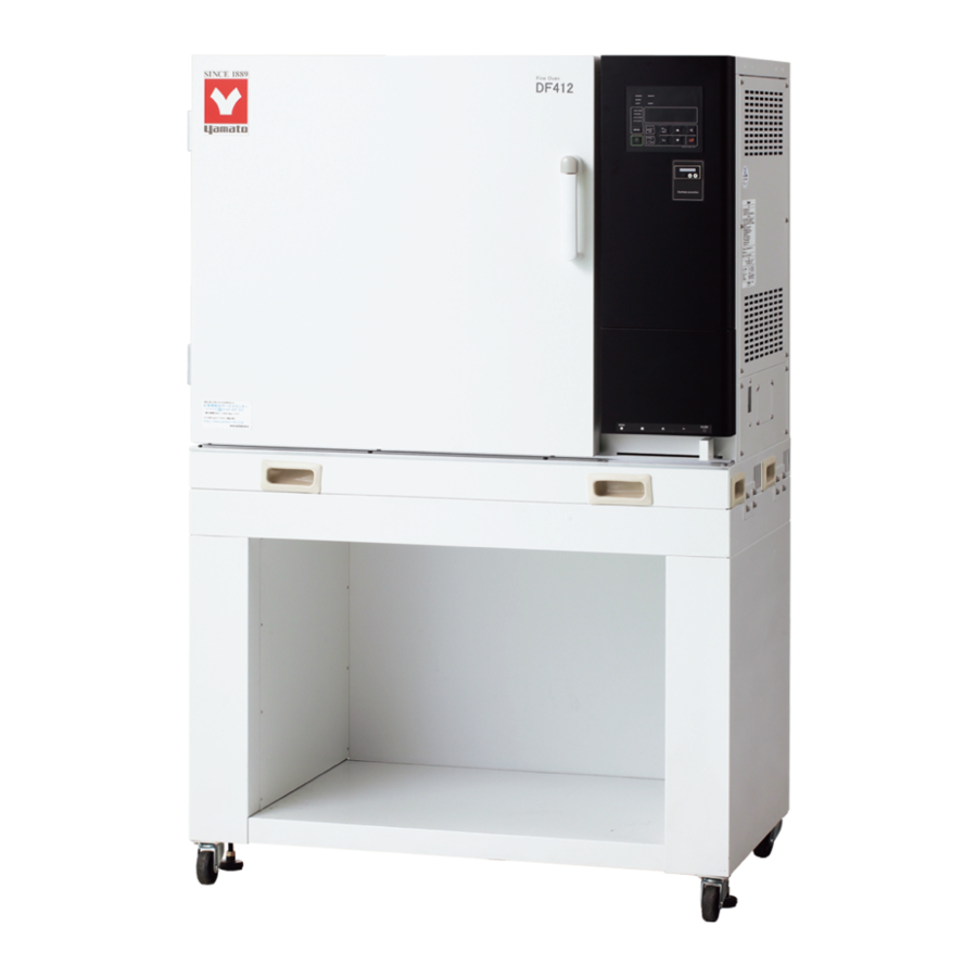
Constant Temperature Precision Oven
(High Accuracy Fine Oven)
Instruction Manual
● Thank you for choosing DF/DH series Precision
Ovens from Yamato Scientific Co., Ltd.
● This
product
applications. For laboratory drying sterilization
only.
● For proper equipment operation, please read this
instruction manual thoroughly before use. Always
keep equipment documentation safe and close at
hand for convenient future reference.
Warning
Yamato Scientific America Inc.
Santa Clara,CA
DF412/612
DH412/612
First Edition
is
not
designed
: Read instruction manual warnings
and cautions carefully and
completely before proceeding.
Ovens Available From:
For Information and to Order
Contact Us At:
323-770-0634 800-574-2748
Email: sales@LRE.com
Web Site: www.LRE.com
for
medical
Printed on recycled paper
Advertisement
Table of Contents
Troubleshooting

Related Manuals for Yamato DF412/612


Summary of Contents for Yamato DF412/612
- Page 1 Constant Temperature Precision Oven (High Accuracy Fine Oven) DF412/612 DH412/612 Instruction Manual First Edition ● Thank you for choosing DF/DH series Precision Ovens from Yamato Scientific Co., Ltd. ● This product designed medical applications. For laboratory drying sterilization only. ● For proper equipment operation, please read this instruction manual thoroughly before use.
-
Page 2: Table Of Contents
Contents 1. SAFETY PRECAUTIONS ............1 Explanation of Symbols ........................1 Symbol Glossary ..........................2 Warnings & Cautions .......................... 3 2. PRE-OPERATION PROCEDURES ........... 4 Installation Precautions & Procedures ....................4 3. COMPONENT NAMES AND FUNCTIONS ..........8 Unit Exterior ............................8 Interior Structure .......................... - Page 3 Accessory Item List ........................... 62 12. WIRING DIAGRAMS ............. 65 DF412/612 Wiring Diagram ......................65 DH412/612 Wiring Diagram ......................66 Wiring Diagram Glossary ........................67 13. LIST OF HAZARDOUS SUBSTANCES ..........68 14. SETUP CHECKLIST ............. 69 Appendix 1 ................ 70 Temperature Build Times By Model ....................
-
Page 4: Safety Precautions
1. SAFETY PRECAUTIONS Explanation of Symbols A Word Regarding Symbols Various symbols are provided throughout this text and on equipment to ensure safe operation. Failure to comprehend the operational hazards and risks associated with these symbols may lead to adverse results as explained below. -
Page 5: Symbol Glossary
1. SAFETY PRECAUTIONS Symbol Glossary Warning Danger!: High Danger!: Danger!: Moving Danger!: General Warning Voltage Extremely Hot Parts Blast Hazard Caution Caution: Do Not Caution: Caution: Caution: May General Caution Heat Without Shock Hazard! Burn Hazard! Leak Water! Water! Caution: Caution: Toxic Water Only Chemicals... -
Page 6: Warnings & Cautions
1. SAFETY PRECAUTIONS Warnings & Cautions Warning NEVER operate equipment near combustible gases/fumes. Do not install or operate DF/DH series unit near flammable or explosive gases/fumes. Unit is NOT fire or blast resistant. Negligent use could cause a fire/explosion. See “List of Hazardous Substances” (P.67) ALWAYS ground equipment. -
Page 7: Pre-Operation Procedures
2. PRE-OPERATION PROCEDURES Installation Precautions & Procedures 1. Choose an appropriate installation site. DO NOT install unit: ・where flammable or corrosive gases/fumes will be generated. ・where ambient temperature will exceed 35ºC, will fall below 5ºC or will fluctuate. ・in excessively humid or dusty locations. ・where there is constant vibration. - Page 8 2. PRE-OPERATION PROCEDURES Installation Precautions & Procedures 4. Check stability. Unit may tip over or fall, causing injury or death during an earthquake or other unforseen incident. Be sure to stabilize unit properly (adjustable leveling feet securely positioned, etc.) to assure safe operation and a safe work area.
- Page 9 Turn off main power switch (ELB) immediately and disconnect from facility terminal or outlet, if power cable becomes partially severed or damaged in any way. Failure to do so may result in fire or electric shock. Contact a local dealer or Yamato sales office for assistance in replacing power cable if it is damaged.
- Page 10 Likewise, smoke and other harmful fumes may be emitted into work area from samples in process. Implement proper ventillation, such as by installing an exhaust hood or by running a proper duct from the exhaust port. Contact Yamato regarding ventilation options for DF/DH series units. Also see Accessory Options on P.62.
-
Page 11: Component Names And Functions
3. COMPONENT NAMES AND FUNCTIONS Unit Exterior Exhaust duct flange (option) Control panel Heat vents Observation window (option – DF only) Door Warning/rating labels Door handle Emergency stop switch (option) Terminal block access for optional output items Chart recorder (option) Power switch (ELB) Stand w/casters... -
Page 12: Interior Structure
3. COMPONENT NAMES AND FUNCTIONS Interior Structure & Configuration Temp control Cable port sensor Axial fan Rack Fan motor Rack support Heater Exhaust port Damper Intake port Damper fully closed Damper Exhaust port Intake port Damper fully open... -
Page 13: Control Panel
3. COMPONENT NAMES AND FUNCTIONS Control Panel Panel Item Description Upper Display Readout for chamber temperature, error code, etc. Lower Display Readout for temperature setting, clock, timer, etc Function Indicator Lamps Illuminates (one or more) to show which function is currently running or active Mode Indicator Lamps Illuminates (one at a time) to show which mode is currently running. -
Page 14: Operation Procedure
4. OPERATION PROCEDURE Prior Confirmation 1. Check power supply and ground wire. Confirm unit power cable is connected to a proper power source and grounded. 2. Check main power switch (ELB). Confirm that ELB functions properly. See “Maintenance Procedure” (P.54). Check ELB performance once a month or before extended perpetual operation. -
Page 15: Setting Date & Time
5 years. Replacing battery within the 5-year lifespan is recommended. Contact a local dealer or Yamato sales office to request a replacement battery. If unit has program data in memory, make a data backup file before replacing backup battery. See “Data Backup”... -
Page 16: Keypad Tone Setting
4. OPERATION PROCEDURE Setting Date & Time 3 Set the date. 1) Press 2) Set the current year using and press 3) Set month/date using and press Press to move cursor position. 4 Set clock. 1) Press 2) Press and set clock using Press ... - Page 17 4. OPERATION PROCEDURE Operation & Function Flow...
-
Page 18: Constant Temperature Operation
3 Set temperature. 1) Press . Changeable digits flash in lower display. 2) Change digit positions using increase or decrease value using Operating temperature ranges: DF412/612: 0~270ºC DH412/612: 0~370ºC 3) Press when temperature setting has been entered. - Page 19 4. OPERATION PROCEDURE Constant Temperature Operation 4 Start operation. Press to start operation. OPERATE and HEATER lamps light and temperature begins building. Lower display in heat build phase: Lower display in temperature stabilization: Lower display in cooling phase: 5 Pause/stop operation Press to manually terminate operation.
- Page 20 4. OPERATION PROCEDURE Quick Auto Stop Operation 6 Set timer The quick auto stop function is used to automatically stop constant temperature operation at a certain time (by clock) or after a desired duration (by timer). (decided during operation). 1) Press with constant temperature operation in progress.
- Page 21 4. OPERATION PROCEDURE Quick Auto Stop Operation 6) When timer runs out or when stop time is reached operation stops, lower display reads 7) Press to clear from display. When operation stops and is cleared, start screen is restored. ...
-
Page 22: Auto Stop Operation
4. OPERATION PROCEDURE Auto Stop Operation AUTO STOP (Automatic Stop) utilizes timer or clock to automatically stop an operation. Operation must be started manually. See below. Auto stop mode set to timer: When auto stop mode is set to the timer, unit enters a wait period, and remains “waiting”... - Page 23 4. OPERATION PROCEDURE Auto Stop Operation 2 Select auto stop mode Press key repeatedly until both FIXED TEMP and AUTO STOP lamps light. Fixed Temperature mode is factory default. Once mode has been changed, the last mode run will be selected on subsequent startups. 3 Set temperature and stop timer/clock 1) Press 2) Select stop TIME or CLOCK (lamp in upper-left...
- Page 24 4. OPERATION PROCEDURE Auto Stop Operation 4 Start operation Press to start operation. OPERATE and HEATER lamps light and temperature begins building. Press at any time during operation to monitor remaining time in the lower display. emaining time display (timer): ...
-
Page 25: Auto Start Operation
4. OPERATION PROCEDURE Auto Start Operation AUTO START (Automatic Start) mode utilizes timer or clock to automatically begin an operation. Operation must be stopped manually. Timer launch Operation start (automatic) SV: Temperature setting, t: Auto start time (time) Set Auto Start mode 1 Turn on power. - Page 26 4. OPERATION PROCEDURE Auto Start Operation Example 1. Auto Start mode set to timer: Operation automatically begins 35 hours and 30 minutes after is pressed. Example 2. Auto Start mode set to clock: Press and operation begins automatically at 15:00 (3:00PM). Start operation 1) Press to enter standby mode (wait) until...
- Page 27 4. OPERATION PROCEDURE Auto Start Operation 3) When start timer runs out or when clock and start time agree, the OPERATE lamp changes from flashing to lighted; HEATER lamp lights and temperature begins building. The quick auto stop function is inoperable during auto start mode.
-
Page 28: Variable Fan Speed
4. OPERATION PROCEDURE Variable Fan Speed The variable fan speed function is beneficial for changing circulation speed to match ventilation flow using 10 different fan motor speeds. Fan speed is the same between settings 1 (about 650rpm) and 9 (about 1400rpm), regardless of whether unit is operating at 50Hz or 60Hz. - Page 29 4. OPERATION PROCEDURE Variable Fan Speed 4 Setting fan speed during operation 1) From 3-1 above, press so that “ ” appears with the “ ” flashing in the lower display. so that current speed setting ( ~ 2) Press ) shows flashing in the upper display.
-
Page 30: Programmed Operation
4. OPERATION PROCEDURE Programmed Operation PROGRAM mode runs a combination of times and temperatures in a series of programmed steps as one operation. See below. Running programs 1 Turn power ON Turn main power switch ON (|) (idle). Press and hold to turn control panel power on (standby). - Page 31 4. OPERATION PROCEDURE Programmed Operation 3 Select program number Press . The program number in lower display will begin flashing. Select desired program number using and press 4 Start programmed operation Press to start programmed operation. Do not attempt to run a cycle if has not been set at the end step in a program.
- Page 32 4. OPERATION PROCEDURE Programmed Operation 5 Operation end 1) When selected program cycle ends, lower display shows and operation stops. 2) Clear by pressing Initial screen is restored. Fan continues running regardless of whether operation is stopped. Press and hold to turn off control panel and stop fan.
-
Page 33: Programming Procedure
4. OPERATION PROCEDURE Programming Procedure Sample program In this example, there are 8 steps in program pattern 2. Steps from 4 to 7 are repeated 5 times and the program ends with step 8. Note: Steps 4 to 7 are run a total of 6 times. Repeat Variable Step... - Page 34 4. OPERATION PROCEDURE Programming Procedure The following outlines the procedure for building the example program on P.30: (This procedure assumes unit is set to factory defaults) Screen status Procedure flashes. III. PROGRAM lamp flashes. - “ ” appearing in upper display indicates that steps for selected program have already been entered and finalized.
- Page 35 4. OPERATION PROCEDURE Programming Procedure Enter program pattern - TEMP flashes in bottom left of lower display. Enter (°C). - Last “ ” in “ ” flashes. Enter “ ” (0 hours and 0 minutes - default). - TIME flashes in bottom left of lower display.
- Page 36 4. OPERATION PROCEDURE Programming Procedure Set “ ” setting to (default). (to program next step, set to ; to enter current step as final, set to All program lamps flash. 1-10 Press and hold setting complete. Input program pattern STEP02 Enter parameters for 2 ~ 6 in the STEPS...
- Page 37 4. OPERATION PROCEDURE Programming Procedure Enter “ ” (repeat begins at Enter “ ” (repeats steps five times) Repeat count may be set between 1 and 99 or to indefinite setting, “ ” (infinity). Turn wait function “ ”. WAIT lamp flashes.
- Page 38 4. OPERATION PROCEDURE Programming Procedure Enter “ ” (0 hours, 30 minutes) Entering “ ” on final step makes time setting indefinite (must be stopped manually). Enter “ ” (No repeat destination) Enter “ ” (No repeats) Set wait function to Wait lamp flashes.
-
Page 39: Copying & Deleting Programs
4. OPERATION PROCEDURE Copying & Deleting Programs Copying programs Press repeatedly until appears, flashing in lower display. Press shows with the “ ” flashing in lower display. Enter the program number to be copied using and press “ ” flashes in upper display. while the lowest available program number (i.e. - Page 40 4. OPERATION PROCEDURE Copying & Deleting Programs Deleting programs Press repeatedly until shows, flashing in lower display. Press shows with the “ ” flashing in lower display. Select a pattern number to delete using , or select (ALL) using then press and hold When “...
-
Page 41: Wait Function Explanation
4. OPERATION PROCEDURE Wait Function Explanation Examples of estimated heating/cooling times with settings designated to WAIT “ON” and WAIT “OFF”. Step Set temp(°C) 0 min 0 min 0 min 5 min 0min 5 min 2 hr Set time Heating and cooling times for steps (1), (3), (5) and (7) are set to 0 min. (full power). Heating time for step (9) is set beyond capacity. -
Page 42: Keypad Lock Function
4. OPERATION PROCEDURE Keypad Lock Function Set keypad lock. 1 Turn control power off (idle) Turn main power switch ON (|). Lower display shows current time. If unit is in standby, press and hold to turn control panel power off (idle). 2 Enter password 1) Press and hold shows in lower display while... -
Page 43: Calibration Offset Function
The -2°C calibration in the example above is applied over the entire temperature setting range (DF412/612: 0~260°C, DH412/612: 0~360°C). Note that offset values may change slightly depending on sample/specimen arrangement in the chamber and/or temperature setting. -
Page 44: Recovery Function
4. OPERATION PROCEDURE Recovery Function Select recovery mode for the event of a power failure. 1 Turn control panel off (idle) Turn main power switch ON (|). Lower display shows the current time. If unit is in standby, press and hold to turn control panel power off (idle). -
Page 45: Co 2 Emissions & Power Consumption Settings
4. OPERATION PROCEDURE Emissions & Power Consumption Settings Setting CO conversion factor & resetting total CO emissions/power consumption. 1 Turn control panel power off Turn main power switch ON (|). Lower screen shows current time. If unit is in standby, press and hold to turn control panel power off (idle). - Page 46 4. OPERATION PROCEDURE Emissions & Power Consumption Settings :CO emission factor. The factory default setting of (0.000550t /kWh) reflects the Environmental Ministry Press Release on 6 November 6, 2013. Applicable value varies by utility company. Contact the servicing utility authority to confirm what value should be used.
-
Page 47: Data Backup, Data Recovery & Reset
4. OPERATION PROCEDURE Data Backup, Data Recovery & Reset Back up data, recover data from backup or reset data to factory default. 1 Turn control panel off Turn main power switch ON (|). Lower screen shows the current time. If unit is in standby, press and hold to turn control panel power off (idle). -
Page 48: Monitoring Data
4. OPERATION PROCEDURE Monitoring Data Current power consumption, accumulated hours of operation, etc. may be viewed by using the data monitoring feature. Setting information shown in upper display cannot be modified. 1 Applicable value shows in upper Monitoring items may be viewed in standby or while display operation is in progress. - Page 49 4. OPERATION PROCEDURE Monitoring Data Heater Output Heater output shows heater power output ratio in a percentage of rated capacity. Output is controlled by a PID operation value between 100 and 0% until temperature setting is reached. Example If upper display shows , ouput is at 45.6% of rated heater capacity.
-
Page 50: Independent Overheat Prevention Device
4. OPERATION PROCEDURE Independent Overheat Prevention Device DF/DH series units feature redundant safety devices: 1) The internal automatic overheat prevention (automatic reset) feature, and 2) the Independent Overheat Prevention Device (IOPD) with discrete power supply, circuit and sensor; completely independent of the CPU board. The IOPD main relay functions to activate and cut power to the heater when chamber temperature goes too far beyond objective temperature. -
Page 51: Handling Precautions
In the event that a foreign object accidentally falls inside, turn off main power (ELB) immediately, disconnect power cable and contact a local dealer, or Yamato sales office for assistance. Continuing to operate unit without removing object may cause fire or electric shock resulting in serious injury or death. -
Page 52: Caution
6. ALWAYS run equipment within specified temperature range. Working temperature range is room temperature +15°C~260°C (DF412/612) and +15°C~ 360°C (DH412/612). Never attempt to operate unit outside of specification range. Equipment malfunction or damage may result. - Page 53 Table 5.1. Do not process test samples which contain any of the substances shown in this table. For further assistance, contact a Yamato sales office or dealer. Table 5.1 - Substances harmful to chamber door seal...
- Page 54 5. HANDLING PRECAUTIONS Caution Material Silicon Rubber Fluoro-rubber Classification Ether Diethyl Ether, Dibutyl Ether, Diethyl Ether, Isopropyl Ether, Ethylene Oxide, Dioxane, Dibutyl Ether, Dibenzyl Ether, Epichlorohydrin, Tetrahydrofuran Ethylene Oxide、Dioxane, Epichlorohydrin, Furfural, Tetrahydrofuran Alcohol Amyl alcohol Multiple Alcohol Cellosolve Acetate, Butyl Cellosolve, Derivative Triacetin Acetic Anhydride, Oleic Acid,...
- Page 55 5. HANDLING PRECAUTIONS Caution 11. Temperature control. The temperature sensor for this unit is installed on the inside wall of the chamber and used to control chamber temperature. Chamber temperature reading, as detected by the sensor, may not always agree with the temperature of test specimens. More often than not, chamber and test sample temperatures will differ largely immediately after opening or closing chamber door.
- Page 56 5. HANDLING PRECAUTIONS Caution 17. Cable port precaution. Whenever a manual temperature gauging sensor or probe is inserted through the cable port, close the port cover as fully as possible and completely seal any gaps with heat-resistant insulation or sealant. If the seal is inadequate, temperature characteristics or other performance properties will be degraded and inaccurate.
-
Page 57: Maintenance Procedures
“Er07” will appear in the upper display. An alarm will also sound and ERROR lamp will illuminate. Main power switch (ELB) and overheat prevention device must be inspected, as prescribed above, prior to every instance of extended or overnight operation. ◆Contact a local dealer or Yamato sales office for further assistance. -
Page 58: Storage And Disposal
Dispose of or recycle this unit in a responsible and environmentally friendly manner. Yamato Scientific Co., Ltd. strongly recommends disassembling unit, as far as is possible, in order to separate parts and recycle them in contribution to preserving the global environment. -
Page 59: Troubleshooting
8. TROUBLESHOOTING Error Codes All possible error codes are shown in Table 8.1 below. On DF/DH series units, operation stops and a sounding alarm accompanies occurring errors. Pressing any key (except ) will pause the alarm. After three minutes alarm will sound again. Upper display shows error code and error source source appears in lower display. - Page 60 8. TROUBLESHOOTING Error Codes Error Error Code Name Causes and their solutions Display Turn ELB OFF, then back ON (reset) and confirm whether backup battery capacity is decreased or is dead. RAM Failure, Replace backup battery backup battery capacity reduced or dead If error cannot be cleared by ELB reset or battery replacement, call for service.
-
Page 61: Troubleshooting Guide
・ Control board failure needing special attention”. ・ Temperature sensor failure (*) Call for service If problem(s) persists , turn off power immediately, disconnect power cable from outlet or terminal and c ontact a local dealer or Yamato sales office for further assistance. -
Page 62: Service And Repair
Requests for Repair When a problem occurs, terminate operation immediately, turn off main power switch (ELB) and disconnect power cable. Contact a local dealer or Yamato sales office for assistance. The following information is required for all repairs. ● Model name ●... -
Page 63: Specifications
10. SPECIFICATIONS Specification Table Product Name Precision Oven DF412 DF612 DH412 DH612 Model Name Forced air circulation and ventilation System Working ambient 5°C~35°C temperature range Single-phase Single-phase Singe-phase Single-phase 220V AC 12.5A 220V AC 17.5A 220V AC 15.5A 220V AC 21.5A Power supply 50/60Hz, voltage variation tolerance: ±10%... - Page 64 10. SPECIFICATIONS Specifications Table (continued from previous page) DF412 DF612 DH412 DH612 Model Name Variable Air Flow Function Power-on Time and Operation Time Accumulation Monitor (up to 65,535 Additional functions hours); Calibration Offset; Monitoring Display for Accumulated Power Consumption, Total CO2 Emissions, and Heater Operation Output; Power Recovery Mode;...
-
Page 65: Accessory Options
DF412/612, DH412/612 Precision Ovens are compatible with a wide variety of available options, shown in Tables 11.1, 11.2.1 and 11.2.2. Options listed in Table 11.2.1 and 11.2.2 are required to be installed at the Yamato manufacturing facility or to be retrofitted by a qualified technician. - Page 66 11. ACCESSORY OPTIONS Accessory Item List Table 11.2 List of options (retrofit required) Option Product Code Option Model Compatible Description Models Remote Terminal installed on main unit for Communications 213712 ODF72 controlling and monitoring operation status Terminal (RS485) from remote PC workstation. Adapter kit for connecting unit to remote External PC workstation.
- Page 67 11. ACCESSORY OPTIONS Accessory Item List Emergency 213708 ODF64 DF/DH412 Button to shut main power off in the event Stop Button of an emergency. 213709 ODF66 DF/DH612 Integrated into main unit. Paperless (inputs: 6), sensor optional (may be used with ODT48). The following three Chart 213707 ODF62...
-
Page 68: Wiring Diagrams
12. WIRING DIAGRAMS DF412/612 Wiring Diagram... -
Page 69: Dh412/612 Wiring Diagram
12. WIRING DIAGRAMS DH412/612 Wiring Diagram... -
Page 70: Wiring Diagram Glossary
12. WIRING DIAGRAMS Wiring Diagram Glossary Symbol Component Symbol Component ELB1 Earth Leakage Breaker (ELB) Model V Motherboard Wiring Terminal Block Model Display Board Independent Overheat Prevention Wiring Terminal Block Device SSR1,2 Solid State Relay Photo Coupler H1,2,3 Heater Door Switch CT1,2,3 Current Sensing Element TH1-1... -
Page 71: List Of Hazardous Substances
13. LIST OF HAZARDOUS SUBSTANCES Never attempt to process explosives, flammables or any items which contain explosives or flammables. ①Nitroglycol, Glycerine trinitrate, Cellulose Nitrate and other explosive nitrate esters ②Trinitrobenzen, Trinitrotoluene, Picric Acid and other explosive nitro compounds ③Acetyl Hydroperoxide, Methyl Ethyl Ketone Peroxide, Benzoyl Peroxide and other organic peroxides ④Metallic Azide, including Sodium Azide, etc. -
Page 72: Setup Checklist
14. SETUP CHECKLIST Setup DF/DH series units using the following procedure: Installed by (company or Installation approved Assessed Model Serial number Installation Date personnel) Assessed Item Procedure Section & Reference Page Specifications Verify inlcuded accessories against Accessories 10. Specifications accessories column. ・Check site visually. -
Page 73: Temperature Build Times By Model
Appendix 1 Temperature Build Times By Model Data shown below is for reference only. Individual results may vary. 1. DF412 DF612... -
Page 74: Temperature Fall Times By Model
Appendix 1 Temperature Build Times By Model Data shown below is for reference only. Individual results may vary 3. DH412 4. DH612... - Page 75 Appendix 2 Temperature Fall Times By Model Data shown below is for reference only. Individual results may vary 1. DF412 2. DF612...
- Page 76 Appendix 2 Temperature Fall Times By Model Data shown below is for reference only. Individual results may vary 3. DH412 4. DH612...
-
Page 77: Program Planning Worksheet
Appendix 3 Program Planning Worksheet Control No. Preparation Model name (Y) (M) (D) date Prepared by Program number Temperature setting Program pattern (℃) (℃) Step № Repeat Program Repetition *Damper Temperature Step Time Wait *Event Setting Dstn Count Speed Aperture TEMP WAIT EVENT... - Page 78 Yamato Scientific Co., Ltd. will replace flawed instruction manuals (pages missing, pages out of order, etc.) upon request. Instruction Manual Precision Oven DF412/612 DH412/612 First Edition April 9, 2015 Revised Visit Our Web Site To View Our Inventory of NEW Yamato Lab Ovens www.LRE.com Or Call 323-770-0634 800-574-2748...
Need help?
Do you have a question about the DF412/612 and is the answer not in the manual?
Questions and answers