Table of Contents
Advertisement
INSTRUCTION MANUAL
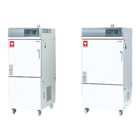
DE410/DE610/DT410/DT610
Model
DE410U/610U
● Thank you very much for buying Yamato Scientific
DE,DT,DEU series.
● For proper use of this unit, please read the instruction
manual and warranty thoroughly before operation. Keep
both for any future references.
Warning:Read and apprehend the important warning
signs in this instruction prior to use.
FOR
CLEAN OVEN
Version 7
Yamato Scientific
This paper has been printed on recycled paper.
Advertisement
Table of Contents

Subscribe to Our Youtube Channel
Related Manuals for Yamato DE410


Summary of Contents for Yamato DE410
- Page 1 CLEAN OVEN DE410/DE610/DT410/DT610 Model DE410U/610U Version 7 ● Thank you very much for buying Yamato Scientific DE,DT,DEU series. ● For proper use of this unit, please read the instruction manual and warranty thoroughly before operation. Keep both for any future references.
-
Page 2: Table Of Contents
Table of Contents For Safety Use ............................1 Explanation of illustrated symbols ....................1 Table of Symbol Mark........................2 Safety Precautions ..........................3 Installation and Preparation for Use ....................4 About the inhalation port........................8 Precautions in Handling ........................9 Emergent Troubleshooting .........................13 Identification of “TROUBLE” and Error Code/Causes..............13 Identification of Parts...........................14 Main unit ............................14 Control Panel ..........................15... -
Page 3: For Safety Use
For Safety Use Explanation of illustrated symbols MEANING OF ILLUSTRATED SYMBOLS Illustrated Symbols Various symbols are used in this safety manual in order to use the unit without danger of injury and damage of the unit. A list of problems caused by ignoring the warnings and improper handling is divided as shown below. -
Page 4: Table Of Symbol Mark
For Safety Use Table of Symbol Mark Warning Warning of High Warning of High Warning of drive Warning of General Warning Potential voltage Temperature section explosion Caution Caution of Caution of low- Caution of water General Caution Caution of scald electric shock water boiling leak... -
Page 5: Safety Precautions
Safety Precautions WARNING Do not use the unit in an area where there is flammable or explosive gas. ■ Never use the unit in an area where there is flammable or explosive gas. For the unit is not explosion-proof, fire/explosion may result. Always ground the unit. -
Page 6: Installation And Preparation For Use
Contact an electrician if you have no equipment for grounding. DE410/DE610, DT410/DT610, DE410U/610U is AC200V three-phase specification. Connect the unit certainly with AC200V outlet or power distribution switchboard. 2.Choose a proper place for installation. - Page 7 3.Choose a correct power distribution board or receptacle. Choose a correct power distribution switchboard or receptacle that meets the oven’s rated electric capacity. Electric capacity : DE410 AC200V three-phase 8.3A DE610 AV200V three-phase 11.5A DT410 AV200V three-phase 11.5A DT610 AV200V three-phase 16.0A DE410U AV200V three-phase 8.3A...
- Page 8 Safety Precautions Installation and Preparation for Use Warning 6. Do not remodel the oven 7. Install the Oven on a level area. Unauthorized modification will be hazardous Do not installation the oven on a non level surface. and cause problems in the operation of the This will cause hazards to the operator and create Oven.
- Page 9 Safety Precautions Installation and Preparation for Use Warning Handling of power code. ● Do not use the power cord if it is bundled or tangled. If it is used in this manner, it can overheat and fire may be caused. ●...
-
Page 10: About The Inhalation Port
Safety Precautions About the inhalation port Warning Ventilating ● When forwarding the unit, the intake port is closed. If you use the unit with the exhaust damper opened to ventilate more effectively, you should remove the cover of the intake port in advance as follows. 1. -
Page 11: Precautions In Handling
Precautions in Handling Warning Substance that can be used Never use explosive substances, flammable substances (shown on page 42 “hazardous Material”), and substances that include explosive or flammable ingredients in the unit. explosion or fire may occur. Do not use this unit if malfunction occurs. You should: If smoke or strange odor should come out of the unit some reason, turn off the power key right away, the turn off the earth leakage breaker and the main power. - Page 12 Precautions in Handling Caution 1. When you use the oven for the first time During the initial operation, the oven may occasionally generate an odor especially when high temperature are reached. This odor is normal and deose not signal a problem with the oven.
- Page 13 Precautions in Handling Caution 7. Do not put anything on the oven. Do not put anything on top pf the oven because they will fall and result in injury to a person. 8. During a thunderstorm. During a thunderstorm, immediately turn off the earth leakage beraker and main power. 9.
- Page 14 Precaution in Handling Caution 12. Do not place any samples on the bottom of the chamber Do not place any samples on the bottom of the chamber to heat, because it may cause that the unit does not work correctly, that the temperature become extraordinary high, and that machine trouble occurs.
-
Page 15: Emergent Troubleshooting
Emergent Troubleshooting Identification of “TROUBLE” and Error Code/Causes blinks blinks blinks TROUBLE lamp flashes. TROUBLE lamp flashes. TROUBLE lamp flashes. Trouble in temperature Trouble in heater control Heater circuit is sensor. materials. disconnected. 、 、 blinks blinks etc. blinks TROUBLE lamp flashes. TROUBLE lamp flashes. -
Page 16: Identification Of Parts
Identification of Parts Main unit Exhaust duct Exhaust damper knob Differential pressure gage Control panel Cable hole Door Door handle Power code Earth leakage breaker... -
Page 17: Control Panel
Identification of Parts Control Panel The Control Panel is shown at Fig.3.3, and the identification of Parts is shown as below. If you need detailed explanation about the specification, function, and operation about controller, refer to the attached instruction manual. ⑪d ⑯... - Page 18 Identification of Parts ⑧ ESCAPE key: Key to cancel the latest entry and recover the status was valid prior to the making the selection. ⑨ Main display: It displays temperature measurements, set values (temperature time, hour, etc.), program information, error information, etc. ⑩...
-
Page 19: Safety Precaution And Check
Safety Precaution and Check Warning If you do not ground the unit, the earth leakage circuit breaker would not work in case of electric leakage. Be sure to connect the ground lead (green core line of the power cord) to the ground wire o terminal of the power source. -
Page 20: Operating Procedure
Operating Procedure Operating Procedure When prepared completely, proceed as follows: 1. Turning of power supply 2. Selection of operation menu Turn on the earth leakage breaker. Press the MENU key several times to select desired operating method. The present time is shown on the sub Press MENU key several times display. -
Page 21: Fixed Temperature Operation Instructions
Fixed temperature operation instructions Selection of operation menu Input of set temperature Changing the set temperature when fixed temp operation is in progress Push either the ▲key or Push the MENU key and Push the ENTER key after select the fixed making a sub-display the ▼key to display the temperature operation... -
Page 22: Auto Start Operation Instruction
Auto start operation instruction Selection of operation menu Input of set temperature Inputting the desired set time Push either the ▲key or Push either the ▲key or Select Auto START mode by pushing the MENU key. the ▼key to display the the ▼key to blink start desired temperature on the time (or the hour) on the... -
Page 23: Auto Stop Operation Method
Auto stop operation method Selection of operation menu Input of set temperature Inputting the desired set time Push either the ▲key or Push either the ▲key or Press the MENU key and select the auto stop the ▼key to blink the the ▼key to blink your operation. - Page 24 Auto stop operation method Selection of wait function Working conditions of timer Press either the ▲key or Auto stop timer activates when: the ▼key to indicate the wait function (ON or OFF) on the main display. Then The wait function is on, press ENTER key.
-
Page 25: Programmed Operation Method
Programmed operation method Selection of operation menu Input of set temperature Input of time Push either the ▲key or Push either the ▲key or Press the MENU key and select the programmed the ▼key to indicate an the ▼key to blink your operation. -
Page 26: Switching From One Operation To Another
Switching from one operation to another This instrument can switch to a different operation mode without stopping the current program no matter what mode it is in, fixed temperature operation, auto-start/stop operation, and program operation. Selection of operation menu Press the MENU key several times unit the desired operation menu lamp flashes on the Operation Menu. -
Page 27: Method Of Using Display Key
Method of using DISPLAY key The display content of the sub display can be changed over by turns when pushed the DISPLAY key. Operation mode Set temperature Fixed temperature operation Hour Remaining time Standby Hour Auto sart operation Set temperature During operation Remaining time(*1) Hour... -
Page 28: How To Use The Mode
How to use the MODE Content of function menu This controller has the other functions bellow. you can choose the function by using the mode key and the ▲key or the ▼key. Press the mode key. Press the MODE key and display your desired function on the main display by pushing either the ▼... -
Page 29: Calibration Offset Function
Calibration Offset Function Outline of Function In the controller, the relationship between the temperature T detected by the sensor and the display temperature of the operation panel D is expressed by the equation of the line which passes the two points (T ) and (T ) shown in Fig.1. -
Page 30: Setting The Calibration Offset Function
Setting the calibration offset function This function can be activated when the controller is in the condition of accepting the MODE key. Bring the oven to the target set temperature 100℃ and allow it to reach the steady state. After then, measure the temperature at a point in the chamber. If it shows 97℃ when the main display shows 100℃, you can conform your measuring value to the one on the display by using calibration offset function. -
Page 31: Safety Devices And Error Codes
9. POST function* POST function is running (See the attached TROUBLE lamp flashes instruction manual “Programmable controller high-tech Ⅳ type”) Contact Yamato Scientifics’ Technical flashes Service Department. 10. Door switch The door is opened. flashes It is not the fault. -
Page 32: Independent Overheat Prevention
2. The purpose of overheating prevention device is to protect the unit from overheating. It does not intend to protect the sample, or to protect them from the accident caused by the use of explose or inflammability.The temperature is set to 280℃ DE410/610,to 220℃ DE410U/610U,to 375℃ DT410/610 at factory shipment. -
Page 33: Behavior After Power Restoration
Behavior after Power Restoration In case of power failure during operation, the controller resumes the following operations after the power restoration. In case of power failure during the program operation 1. The controller automatically resumes the program operation when it left at the power shutdown. 2. -
Page 34: Maintenance And Inspection
Replace the HEPA filter with a new one if the differential pressure comes up to the values shown as below while running in the standby state. Contact our sales or service representative. 50Hz Area 60Hz Area DE410/DT410/DE410U 250 Pa 290 Pa DE610/DT610/DE610U... -
Page 35: Long Storage
Long Storage Long storage and disposal Caution Warning When you do not use the oven for a long When you dispose of the oven. period of time. Do not leave it where children can access. Disconnect the power cable from the power switchboard. -
Page 36: After Service And Warranty
After service and WARRANTY If a Service Call is required Warranty Card (attached to your Oven) If a problem occurs with the Drying Oven, The warranty card is given from the sales or record the error code on the display and stop service representative. -
Page 37: Specifications
Specifications Model DE410 DE610 DT410 DT610 Performance: Operating temperature Room temperature +30~260℃ Room temperature +30~360℃ ±0.3℃ (at 260℃) ±0.3℃ (at 360℃) Temperature stability *1 ±2.5℃ (at 260℃) ±4.0℃ (at 360℃) Temperature uniformity About 70 min About 60 min About 80 min Time to reach max. - Page 38 Specifications Model DE410U DE610U Performance: Operating temperature Room temperature +50~200℃ ±0.3℃ (at 200℃) Temperature stability *1 ±4℃ (at 200℃) Temperature uniformity About 60 min (to 200℃) Time to reach max. Temp. *1 Degree of clean. *1 Class 100 during temperature stability Function / Structure: Temperature control method PID control by microprocessor...
-
Page 39: Wiring Diagram
Wiring Diagram DE410/610/410U/610U・DT410... - Page 40 Wiring Diagram DT610...
-
Page 41: Replacement Parts Table
Replacement parts table DE410 Code № Symbol Part Name Specifications CT1,2,3,4 Current Transformer 2-17-001-0002 CTL-6-S-400 Earth leakage breaker 2-06-008-0004 BJC3-15-3N AC200V Fan motor 2-14-001-0018 MLH2075Z AC200V H1,2,3 Heater DE42S-30010 AC200V 830W DoorSW Door switch LT00035254 OMRON LAB1(recreation) PCB1 PIO board... - Page 42 Replacement parts table DT410 Code № Symbol Part Name Specifications CT1,2,3,4 Current Transformer 2-17-001-0002 CTL-6-S-400 Earth leakage breaker 2-06-008-0004 BJC3-15-3N AC200V Fan motor 2-14-001-0018 MLH2075Z AC200V H1,2,3 Heater DT42S-30430 AC200V 830W DoorSW Door switch LT00035254 OMRON LAB1(recreation) PCB1 PIO board 1-24-000-0024 PCB2 PLANAR board...
- Page 43 Replacement parts table DE410U Code № Symbol Part Name Specifications CT1,2,3,4 Current Transformer 2-17-001-0002 CTL-6-S-400 Earth leakage breaker 2-06-008-0004 BJC3-15-3N AC200V Fan motor 2-14-001-0018 MLH2075Z AC200V H1,2,3 Heater DE42S-30430 AC200V 830W DoorSW Door switch LT00035254 OMRON LAB1(recreation) PCB1 PIO board 1-24-000-0024 PCB2 PLANAR board...
-
Page 44: Hazardous Material
Hazardous Material 1.Nitroglycol, Nitroglycerin, Nitrocellulose, and other explosive nitric esters. Explosives 2.Trintrobenzens, Trinitrotoluene, Picric acid, and other explosive Explosives nitro compounds. Substances 3.Peracetic acid, Methyl ethyl ketone peroxide, Benzoyl peroxide, and other organic peroxides. Metallic lithium, Metallic potassium, Metallic sodium, Yellow phosphorus, Phosphorus sulfide, Red phosphorus, Celluloid, Combustible Calcium carbide, Lime phosphate, Magnesium powder, Aluminum... -
Page 45: List Of Symbols In The Display
List of Symbols in the display The oven has the controller with the 7-digit LED display. The meaning of symbols in the display is as follows: Besides some symbols are not displayed in type of ovens. Capital Symbol Meaning of Abbreviation Meaning of Symbol in the display abnd Abnormal end... - Page 46 List of Symbols in the display Capital Symbol Meaning of Abbreviation Meaning of Symbol in the display End: Setting mode for program end er.** Error (abnormal) code number** error Escape function (The function at the time when you stop escape selecting mode on the way or you redo to input/edit the program) fn.**...
- Page 47 p.tmp Preset temperature preset temperature List of Symbols in the display Capital Symbol Meaning of Abbreviation Meaning of Symbol in the display pump Pump r.cnt Repeat frequency setting mode repeat count Ready: The condition that is able to transfer to ready the printer real...
- Page 48 wt.** Wait function of Segment** wait.** year The Christian era...
-
Page 49: Operational Procedures Of Type Ⅳ Controller
Operational Procedures of Type Ⅳ Controller Run “MENU” Menu key Fixed temperature Program operation operation When you run the oven in a programmed operation, proceeds as follows. A feasible program number will appear on Select the program number the main display by using either the ▲key or Displays set the ▼key and then press the... -
Page 50: Program "Mode
Program “MODE” MODE Main display See the programming flowchart Inputting and deliting programs(ProG) Programming NOTE:If there are no programs, this will not appear ▼ ▲ ENTER key ENTER key Deleting programs *The number of existing Select the programs programs will appear on the sub number that you want display delete... -
Page 51: Flowchart For Programming
Flowchart for programming Segment condiguration : Segments are made up of the At the following step, when you want to return the previous MODE key following items, and must be input step, push the "ESCAPE key" in this order Press ▼... - Page 52 Be sure to use the unit strictly following the handling and operating instructions in this operating instruction. Yamato Scientific Co., Ltd. assumes no responsibility for an accident or a malfunction caused by use of this product in any way not specified in this operating instruction.
Need help?
Do you have a question about the DE410 and is the answer not in the manual?
Questions and answers