Table of Contents
Advertisement
Quick Links
High temp oven
Instruction Manual
Thank you for choosing High Temp oven DR201 from
Yamato Scientific Co., Ltd.
●For proper equipment operation, please read and
become thoroughly familiar with this instruction
manual before use. Always keep equipment
documentation safe and close at hand for convenient
future reference.
Warning: Read instruction manual warnings
and cautions carefully and
completely before proceeding.
Yamato Scientific Co. Ltd.
DR201
First Edition
Printed on recycled paper
Advertisement
Table of Contents
Troubleshooting

Subscribe to Our Youtube Channel
Related Manuals for Yamato DR201


Summary of Contents for Yamato DR201
- Page 1 High temp oven DR201 Instruction Manual First Edition Thank you for choosing High Temp oven DR201 from Yamato Scientific Co., Ltd. ●For proper equipment operation, please read and become thoroughly familiar with this instruction manual before use. Always keep equipment documentation safe and close at hand for convenient future reference.
-
Page 3: Table Of Contents
WARNING / CAUTION ......................3 Residual Risk Map ......................... 5 1. SAFETY PRECAUTIONSList of Residual Risks ..............6 2. COMPONENT NAMES AND FUNCTIONS ................9 This product (DR201) ......................9 Control panel ........................10 Display Characters ......................11 3. PRE-OPERATION PROCEDURES ..................12 Installation Precautions ...................... - Page 4 7. MAINTENANCE PROCEDURES .................... 48 Precautions before Inspection ..................... 48 Precautions in Daily Maintenance ..................48 Maintenance and Inspection ....................48 8. EXTENDED STORAGE AND DISPOSAL................49 Extended storage ......................... 49 Disposal Considerations ...................... 49 9. TROUBLESHOOTING ......................50 Reading Error Codes ......................
-
Page 5: Safety Precautions
1. SAFETY PRECAUTIONS Explanation of Symbols... -
Page 6: Symbol Glossary
1. SAFETY PRECAUTIONS Symbol Glossary WARNING / CAUTION Danger! Danger! Danger! Danger! General High Voltage Extremely Hot Moving Parts Blast Hazard Caution: Caution: Caution: Caution: Caution: Do Not Heat Water Only Shock Hazard! Burn Hazard! May Leak Water! Without Water! Caution: Toxic Chemicals RESTRICTION... -
Page 7: Warning / Caution
1. SAFETY PRECAUTIONS WARNING / CAUTION WARNING Install in a location free of flammables and explosives. Never install or operate unit in a flammable or explosive gas atmosphere. Unit is NOT fire or blast resistant. Simply switching earth leakage breaker (ELB) "ON" or "OFF" can produce a spark, which can then be relayed during operation, causing fire or explosion when near flammable or explosive fluids, chemicals or gases/fumes. - Page 8 1. SAFETY PRECAUTIONS WARNING / CAUTION Handle power cable with care. ・Do not operate unit with power cable bundled or tangled. Operating unit with the power cable bundled or otherwise tangled, may cause power cable to overheat and/or catch fire. ・Do not modify, bend, forcibly twist or pull on power cable.
-
Page 9: Residual Risk Map
1. SAFETY PRECAUTIONS Residual Risk Map These figures indicate positions of caution labels. The numbers shown in the figure indicate the numbers listed in the "List of Residual Risks" in this manual. For details of individual residual risks, see the List of Residual Risks. Caution label-HOT Rating label 2,3,6,7,10,14,19,20,22,26,28,29,30... -
Page 10: Safety Precautionslist Of Residual Risks
1. SAFETY PRECAUTIONS 1. SAFETY PRECAUTIONSList of Residual Risks List of residual risks (instructions for risk avoidance) This list summarizes residual risks to avoid personal injuries or damages to properties during or related to the use of equipment. Be sure to fully understand or receive instructions on how to use, maintain and inspect equipment before starting operation. - Page 11 1. SAFETY PRECAUTIONS List of Residual Risks Degree of Risk Protective measures taken by the user Relevant risks description page DO NOT process explosive or flammable P.45 WARNING Explosion/fire substances When using resin containers for processing, use P.45 WARNING Fire caution not to exceed their heat-resistant temperature.
- Page 12 1. SAFETY PRECAUTIONS List of Residual Risks Daily inspection/maintenance Degree of Risk Protective measures taken by the user Relevant risks description page Be sure to disconnect power cable before daily P.48 Fire/Electri WARNING inspection and maintenance. c shock Perform inspections and maintenance when unit is P.48 WARNING Burn...
-
Page 13: Component Names And Functions
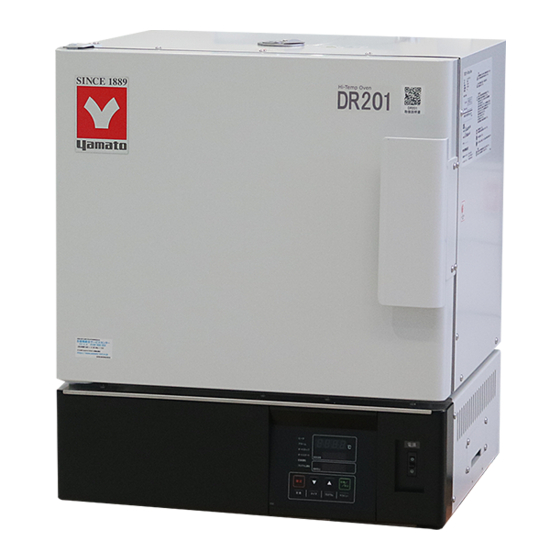
2. COMPONENT NAMES AND FUNCTIONS This product (DR201) ◆ Front QR code label Instruction manual can be downloaded from Yamato website. Chamber rack Standard attachment: 2 pcs Serial No./Rating label Vents Intake open air Door Rack support Earth Leakage Breaker (15 A) Number of rack tiers: 3 tiers ON: "|"... -
Page 14: Control Panel
2. COMPONENT NAMES AND FUNCTIONS Control panel ⑧ ⑭ ⑨ ⑩ ⑮ ⑪ ⑫ ⑯ ⑬ ③ ② ② ① ④ ⑤ ⑥ ⑦ No Panel Item Description RUN/STOP Key Press one second to start or stop an operation ① ▼▲keys Press to increase or decrease the setting value ②... -
Page 15: Display Characters
2. COMPONENT NAMES AND FUNCTIONS Display Characters All characters displayed when making settings and during operation are defined as follows: Character Letters Panel Item Purpose Fixed temperature Appears during Fixed temperature operation operation Temperature Appears while entering temperature settings for Fixed setting temperature operation and timed operations AStP... -
Page 16: Pre-Operation Procedures
3. PRE-OPERATION PROCEDURES Installation Precautions Choose an appropriate installation site. DO NOT install unit: ・ where installation surface is not completely level, not even or not clean. ・ where flammable or corrosive gases/fumes may be present ・ where external temperature will exceed 35°C, will fall below 5°C or will fluctuate largely. - Page 17 Connect power cable to a suitable facility outlet or terminal, according to the electrical requirements. DR201: 115 V AC single phase 50/60 Hz 11.5A (ELB capacity 15 A) : 220 V AC single phase 50/60 Hz 6.0A (ELB capacity 10 A) Operational voltage range is ±10 % of power rating, performance guarantee voltage...
- Page 18 3. PRE-OPERATION PROCEDURES Installation Precautions Install in a dry location. Install unit where it will be free from liquid spray and other moisture. Failure to do so may result in control mechanisms becoming wet, causing malfunction, electrical shock and/or fire. Please do not use it in two layers.
-
Page 19: Pre-Operative Preparations
4. PRE-OPERATIVE PREPARATIONS Operation Modes and Functions Operation modes for this unit are defined in the table below Description Page P.21 Fixed temperature operation This mode runs unit at a constant selected temperature. Auto stop operation P.23 This mode is used to automatically terminate an operation when a specified time period has passed (decided before operation). - Page 20 4. PRE-OPERATIVE PREPARATIONS Operation Modes and Functions Operation functions for this unit are defined in the table below: Description Page Automatic overheat prevention This function is set to automatically activate when chamber temperature exceeds the temperature setting by 12 °C. -...
-
Page 21: Mode & Function Flow
4. PRE-OPERATIVE PREPARATIONS Mode & Function Flow The following chart illustrates operation flow of Fixed temperature operation and timed operations. - Page 22 4. PRE-OPERATIVE PREPARATIONS Mode & Function Flow The following chart illustrates operation flow of Program operation and Submenu.
-
Page 23: Overheat Prevention Device Setup
4. PRE-OPERATIVE PREPARATIONS Overheat Prevention Device Setup Setting range/function The overheat prevention device temperature setting range is from 0 °C to 50 °C (750 °C)beyond the maximum temperature setting of this unit. When chamber temperature exceeds objective temperature setting and reaches that of the overheat prevention device, the heater circuit is shut off and error code "Er19"... -
Page 24: Installing Chamber Racks
4. PRE-OPERATIVE PREPARATIONS Installing chamber racks Chamber rack in the chamber interior can be set at any position on the three-tiered rack support plate depending on the size and amount of the sample. This unit includes two chamber rack. Set it on the rack support plate in the Chamber interior. -
Page 25: Operation Procedures
5. OPERATION PROCEDURES Fixed Temperature Operation 1. Turn ON (|) power (ELB) Run a Fixed temperature operation Initial values will be shown for about five seconds after power-on, then displays will switch to the initial settings screen, showing current chamber temperature (top), operation mode character (center) and overheat prevention setting (bottom). -
Page 26: Quick Auto Stop Operation
5. OPERATION PROCEDURES Quick Auto Stop Operation ・Run a Quick auto stop operation 1. Set timer during Fixed temperature operation ① Make sure that unit is running Fixed temperature operation by confirming that FIXED TEMP lamp is illuminated, then press the TIMER key. -
Page 27: Auto Stop Operation
5. OPERATION PROCEDURES Auto Stop Operation ・Run an Auto stop operation 1. Set stop time ① Press the TIMER key on the initial settings screen. Mode used in the previous session will be shown in center display. ② Press the TIMER key again and center display will begin flashing. - Page 28 5. OPERATION PROCEDURES Auto Stop Operation ・Wait mode for Auto stop operation Timer will start counting down after chamber temperature reaches the target temperature. When Wait is set to “on” and temperature reading comes outside the range of target temperature ±3 °C, timer will stop counting. When set to “oFF”, timer continues counting regardless of the deference between temperature reading and temperature setting.
- Page 29 5. OPERATION PROCEDURES Auto Start Operation ・Run an Auto start operation 1. Set start time ① Press the TIMER key on the initial settings screen. Mode used in the previous session will be shown in center display. ② Press the TIMER key again and center display will begin flashing.
- Page 30 5. OPERATION PROCEDURES Auto Start Operation 2. Start operation ⑧ Press the RUN/STOP key for about one second after setting the timer. FIXED TEMP and AUTO START lamps will illuminate, indicating Auto start operation has started. Operation begins automatically when timer reaches 0.00. 3.
-
Page 31: Program Operation Auto Start
5. OPERATION PROCEDURES Program Operation Auto Start ・Run a Program auto start operation 1. Set start time For details on entering programs, see "Program Operation” (P.29) ① Press the TIMER key on the initial settings screen. Mode used in the previous session will be shown in center display. - Page 32 5. OPERATION PROCEDURES Program Operation Auto Start 2. Start operation ⑧ Press the RUN/STOP key for about one second after setting the timer. AUTO START and PROGRAM lamps will illuminate, indicating Program auto start mode has started. Program operation starts automatically when timer reaches 0.00.
-
Page 33: Program Operation
5. OPERATION PROCEDURES Program Operation ・Program operation This operation is used to run a combination of temperatures, times and modes as one operation. In the figure below, the line pattern which indicates time variation of the set temperature is called "program", and each straight line which is a combination of set temperature and set time is called "step". - Page 34 5. OPERATION PROCEDURES Program Operation ・Temperature rise/fall time The temperature rise and fall times for each temperature difference of 100 ° C are as follows. Numeric values signify time needed (in minutes) for temperature to rise or fall. [Example: Approximately 47 minutes to increase from 400 °C to 500°C].Time for temperature rise and fall varies depending on the exhaust air volume and load.
- Page 35 5. OPERATION PROCEDURES Program Operation 2. Enter program ③ Press the ENTER key. Top display will show , signifying the total number of program steps. The number of steps already entered will flash in center display. ※ Program steps can be set up to 30 steps for PrG1, 15 steps for PrG2 and PrG3, and 10 steps for PrG4 to PrG6.
- Page 36 5. OPERATION PROCEDURES Program Operation ⑦ Press the ENTER key. , indicating timer setting for step 1, will be shown in top display. Current timer setting will also be shown flashing in center display. ⑧ Set the timer for step 1 using the ▲▼ keys. Before setting the timer, be sure to confirm temperature ...
- Page 37 5. OPERATION PROCEDURES Program Operation 4. End Program operation ⑪ A buzzer sounds for about five seconds when program ends. Top display will show , indicating that program has finished. Press the RUN/STOP key to finish Program operation. Displays will return to initial settings screen. Pressing the RUN/STOP key for about one second during ⑪...
-
Page 38: Wait Function
5. OPERATION PROCEDURES Wait Function ・Wait Function Wait mode for Program operation is to prevent operation to proceed next step, or to pause timer count while chamber temperature is outside the range of target temperature ±3 °C. This setting can be made on each step. With this mode “on”, unit will not move to the next step unless the temperature reaches the target temperature ±3 °C, even when the preset time has... -
Page 39: Repeat Function
5. OPERATION PROCEDURES Repeat Function ・Repeat function This section illustrates how to use the repeat function (repeat a program pattern) in a programmed operation. Repeat setting Set the step number to be repeated "PS_n", and number of times to repeat "Pc_n" (n = step number) for the example in “2. Enter program”... -
Page 40: Program Planning Worksheet
5. OPERATION PROCEDURES Program Planning Worksheet Do not write in this manual. Please make copies. Input PrG1 PrG2 PrG3 PrG4 PrG5 into: PrG6 Date Project Name Programmer Program pattern... - Page 41 5. OPERATION PROCEDURES Program Planning Worksheet Do not write in this manual. Please make copies. PrG1 PrG2 PrG3 PrG4 PrG5 Input into: PrG6 Date Project Name Programmer Input value Repeat function Temperature Wait setting Time (h:m) (Point of return (°C) (ON/OFF) :number of times) Step 1...
-
Page 42: Other Functions: Calibration Offset
5. OPERATION PROCEDURES Other Functions: Calibration Offset The calibration offset feature makes it possible to compensate for ・Using calibration any difference between temperature reading on the control panel offset and actual chamber temperature (taken manually). This enables parallel compensation in either direction (+ or -) over the entire temperature setting range. -
Page 43: Other Functions: Keypad Lock
5. OPERATION PROCEDURES Other Functions: Keypad Lock This function locks all the keys that may change setting values. ・Using keypad lock With the keypad lock function ON, all keys become unresponsive except the RUN/STOP and SUBMENU keys. ( will show in top display) Default setting is “oFF”. -
Page 44: Other Functions: Auto-Resume Function
5. OPERATION PROCEDURES Other Functions: Auto-resume Function Unit may restart operation or may be switched into standby state ・Auto-resume mode after power failure, by selecting “on” or “oFF” of this mode. select With this setting “on” unit automatically resume operation, and remain standby when set to “oFF”. -
Page 45: Options (Output Terminal)
5. OPERATION PROCEDURES Options (Output Terminal) ・Before use Operate this unit according to the procedure described in this Instruction manual. Failure to follow the operation procedure described herein may result in a problem. The guarantee will not apply if you operate the unit in a wrong manner. CAUTION 1. - Page 46 5. OPERATION PROCEDURES Options (Output Terminal) ・Specifications External communications Connection: M4 screw terminal block terminal See next page for overview of the standards. (RS-485) Outputs the voltage (DC) corresponding to the measured temperature Output temperature range: 0 to 700 °C, this is default setting and Temperature output terminal can be changed.
-
Page 47: Options (External Communications Terminal)
・ Optional accessory "External communications adapter (RS485-USB) OA017" permits the following connections. (PC not included) Sample program → http://www.yamato-net.co.jp/support/program/index.htm USB-RS485 converter unit: System Sacom USB-485I RJ45-T4P Communication cable: UL2464TASB 2-lead AWG20 cable 3 m, with Y terminal on main unit side. USB cable: 1.8 m, included with USB-485I... - Page 48 5. OPERATION PROCEDURES Options (External Communications Terminal) 1.4 Communication settings Setting items and parameters for this controller is defined in the table below. Item Communication settings Default values Communication Toho (0)/Modbus-RTU (1)/ Toho (0) protocol Modbus-ASCII (2) BCC check Enable (b)/Disable (n) Enable (b) Data length 7/8 bits...
-
Page 49: Handling Precautions
6. HANDLING PRECAUTIONS Warnings and Cautions WARNING NEVER process explosive or flammable substances Never attempt to process explosives, flammables or any items which contain explosives or flammables. Fire or explosion may result. See " LIST OF HAZARDOUS SUBSTANCES" (P.56) Resin container advisory. When using resin containers for processing, confirm that they conform to the heating specifications of this unit. - Page 50 6. HANDLING PRECAUTIONS Warnings and Cautions CAUTION Opening/Closing door When opening or closing the door keep hands and face away from area that the door swings. The door may impact with them causing an injury. DO NOT process corrosive items. Do not process items containing corrosive chemicals of any kind.
- Page 51 6. HANDLING PRECAUTIONS Warnings and Cautions Exercise caution when processing heat-generating substances. Note that temperature reading may not be consistent when processing heat- generating samples. (samples mentioned herein shall not have risk of explosion or ignition) Use calibration offset function to correct temperature reading. If there is a discrepancy between temperature reading and actual chamber temperature, refer to "Calibration Offset"...
-
Page 52: Maintenance Procedures
7. MAINTENANCE PROCEDURES Precautions before Inspection WARNING Be sure to disconnect power cable before daily inspection and maintenance. Perform inspections and maintenance when unit is at room temperature. Never attempt to disassemble unit. Precautions in Daily Maintenance CAUTION ... -
Page 53: Extended Storage And Disposal
Dispose of this unit in accordance with local laws and regulations. Dispose of or recycle this unit in a responsible and environmentally friendly manner. Yamato Scientific Co., Ltd. strongly recommends disassembling unit, as far as is possible, in order to separate parts and recycle them in contribution to preserving the global environment. Major... -
Page 54: Troubleshooting
9. TROUBLESHOOTING Reading Error Codes Unit has a self-diagnostic function built into the CPU board. The table below shows possible causes when safety function is triggered. If unit does not reset by turning OFF (◯) and ON (|) ELB, contact original dealer of purchase. -
Page 55: Troubleshooting Guide
9. TROUBLESHOOTING Troubleshooting Guide Troubles Symptom Possible causes Unit does not turn on when Power cable is not connected securely to power terminal or main power switch is turned outlet. "ON" Power failure in progress No power from power supply, or supply voltage is low. Temperature does not rise. -
Page 56: Service & Repair
Warranty card (attached separately) Warranty card will be handed by dealer or Yamato personnel upon delivery and installation, or will be attached to equipment if no one from dealer or Yamato is to be present at delivery and installation. Register warranty card at https://www.yamato-net.co.jp/support/warranty.htm https://www.yamato-net.co.jp/support/warranty.htm... -
Page 57: Specifications
11. SPECIFICATIONS Model DR201 System Natural convection Operating ambient 5 to 35 °C temperature range Temperature setting 0 to 700 °C range Temperature 300°C~700 °C control range Temperature control accuracy ±5 °C(at700 °C JTM K05) Temperature 10 °C (at 700 °C JIS) - Page 58 11. SPECIFICATIONS Model DR201 Self-diagnostic functions (Automatic overheat prevention, Temperature sensor failure, Heater disconnection, SSR short circuit, main relay failure, Safety devices memory error, internal communication error, abnormal temperature reading), Overcurrent ELB, Overheat prevention device Internal 250 x 250 x 220 dimensions *2 (W ×...
-
Page 59: Optional Accessories
Table 12.1 and Table 12.2 show the option setting list. Options are available for the DR201 type. * Some options are required to be installed at the Yamato manufacturing facility. Table 12.1 list of Options (can be installed after delivery) -
Page 60: List Of Hazardous Substances
13. LIST OF HAZARDOUS SUBSTANCES Never attempt to process explosives, flammables or any items which contain explosives or flammables. Table 13.1 List of hazardous substances ①Nitroglycol, Glycerine trinitrate, Cellulose Nitrate and other explosive nitrate esters ②Trinitrobenzen, Trinitrotoluene, Picric Acid and other explosive nitro compounds ③Acetyl Hydroperoxide, Methyl Ethyl Ketone Peroxide, Benzoyl Peroxide and other organic peroxides ④Metallic Azide, including Sodium Azide, etc. -
Page 61: Standard Installation Manual
14. STANDARD INSTALLATION MANUAL Install this equipment according to following format (check options and special specifications separately). Charged Personnel or Installation Installation Model Serial Number Company Name for Judgment Date proved by Installation Chapter No. & Reference page of instruction Judg №... - Page 62 Doing so may result in equipment malfunction, serious personal injury or death. Notice ● Instruction manual descriptions and specifications are subject to change without notice. ● Yamato Scientific Co., Ltd. will replace flawed instruction manuals (pages missing, pages out of order, etc.) upon request. Instruction Manual...
Need help?
Do you have a question about the DR201 and is the answer not in the manual?
Questions and answers