Sun Microsystems Sun Fire X4150 Service Manual
For 1u systems
Hide thumbs
Also See for Sun Fire X4150:
- Administration manual (150 pages) ,
- Installation manual (107 pages) ,
- Product notes (74 pages)

Subscribe to Our Youtube Channel
Related Manuals for Sun Microsystems Sun Fire X4150


Summary of Contents for Sun Microsystems Sun Fire X4150
-
Page 1: Service Manual
Sun Fire X4150 Server Service Manual For 1U Systems Sun Microsystems, Inc. www.sun.com Part No. 820-1852-13 November 2009, Revision 01 Submit comments about this document by clicking the Feedback[+] link at: http://docs.sun.com... - Page 2 PREALABLE DE SUN MICROSYSTEMS, INC. Cette distribution peut des éléments développés par des tiers. Sun, Sun Microsystems, le logo Sun, Java, Solaris, et Sun Fire sont des marques de fabrique ou des marques déposées de Sun Microsystems, Inc., ou ses filales, aux Etats-Unis et dans d’autres pays. Intel est une marque de fabrique ou une marque déposée de Intel Corporation ou de sa filiale aux Etats-Unis et dans d’autres pays.
-
Page 3: Table Of Contents
Infrastructure Boards 1–4 1.2.2 Dimensions 1–5 1.2.3 System Cables 1–5 Sun Fire X4150 Server Front Panel Features 1–6 Sun Fire X4150 Server Rear Panel Features 1–7 Illustrated Parts Breakdown 1–8 Preparing to Service the System 2–1 Safety Information 2–1 Required Tools 2–2 Obtaining the Chassis Serial Number 2–2... - Page 4 Detecting Fan Module Failure 3–10 3.3.4 Removing a Fan Module 3–11 3.3.5 Installing a Fan Module 3–12 Servicing Power Supplies 3–14 3.4.1 Detecting Power Supply Failure 3–14 3.4.2 Power Supply LED Reference 3–14 Sun Fire X4150 Server Service Manual • November 2009...
- Page 5 To Remove a PCIe Riser 14 ▼ To Install a PCIe Riser 16 Servicing PCIe Cards 4–17 4.4.1 Sun Fire X4150 Server PCIe Card Guidelines 4–18 ▼ To Remove PCIe Cards 18 ▼ To Install PCIe Cards 19 Servicing the Battery 4–20 ▼...
- Page 6 Installing the Front Control Panel Light Pipe Assembly 5–13 Servicing the Power Distribution Board (PDB) 5–13 5.5.1 Removing the Power Distribution Board 5–13 5.5.2 Installing the Power Distribution Board 5–15 Servicing the Paddle Card 5–16 Sun Fire X4150 Server Service Manual • November 2009...
- Page 7 5.6.1 Removing the Paddle Card 5–17 5.6.2 Installing the Paddle Card 5–17 Servicing Cables 5–18 5.7.1 Removing Drive Cables in a SAS Configuration 5–19 5.7.2 Installing Drives Cables in a SAS Configuration 5–20 5.7.3 Removing Drive Cables in a SATA Configuration 5–22 5.7.4 Installing Drive Cables in a SATA Configuration 5–24 5.7.5...
- Page 8 BIOS Advanced Menu Screens C–7 C.2.3 BIOS Boot Menu Screens C–15 C.2.4 BIOS Server Menu Screens C–19 C.2.5 BIOS Security Menu Screens C–24 C.2.6 BIOS Exit Menu Screens C–26 Index Index–1 viii Sun Fire X4150 Server Service Manual • November 2009...
-
Page 9: Preface
Preface The Sun Fire X4150 Server Service Manual provides detailed procedures for removing and replacing replaceable parts in the Sun Fire™ X4150 Server. This manual also includes information about the use and maintenance of the server. This document is written for technicians, system administrators, authorized service providers (ASPs), and users who have advanced experience troubleshooting and replacing hardware. -
Page 10: Related Documentation
BIOS Screens contains examples of typical BIOS screens. Related Documentation To view the latest Sun Fire X4150 server documentation online, go to , and then navigate to Sun Fire X4150 server documentation. http://docs.sun.com The following table lists the available documents. -
Page 11: Index
Before You Read This Document To fully use the information in this document, you must have thorough knowledge of the topics discussed in the Sun Fire X4150 Server Product Notes. Sun Online The following table shows where to find Sun documents online. -
Page 12: Safety Symbols
To submit your comments, go to: http://www.sun.com/hwdocs/feedback Please include the title and part number of your document with your feedback: Example: Sun Fire X4150 Server Service Manual, part number 820-1852-13. Sun Fire X4150 Server Service Manual • November 2009... -
Page 13: Sun Fire X4150 Server Overview
C H A P T E R Sun Fire X4150 Server Overview This chapter provides an overview of the features of the Sun Fire X4150 Server. The following information is included: Section 1.1, “Product Description” on page 1-1 ■ Section 1.2, “Sun Fire X4150 Server Chassis Overview” on page 1-3 ■... - Page 14 (x8 electrical/x16 mechanical) Power • AC power: 100–120/200–240 V AC, 12/6 A, 50–60 Hz • 1 or 2 hot-swappable 650W power supply units (PSUs) to provide N+N redundancy, with energy efficient design Sun Fire X4150 Server Service Manual • November 2009...
-
Page 15: Sun Fire X4150 Server Chassis Overview
Java™ Enterprise System with a 90-day trial license See the Product Release Notes for additional items. Sun Fire X4150 Server Chassis Overview The Sun Fire X4150 Server is based on an all-new chassis family. Chapter 1 Sun Fire X4150 Server Overview... -
Page 16: Infrastructure Boards
1.2.1 Infrastructure Boards The Sun Fire X4150 Server has the following boards installed in the chassis. The boards are listed in TABLE 1-2 Infrastructure Boards TABLE 1-2 Board Description Reference The motherboard includes CPU modules, slots for 16 DIMMs, Section 4.6, “Servicing... -
Page 17: Dimensions
Depth 711.2 mm/28.0 inches Weight Minimum: 13.9 kg/30.6 lbs. Maximum: 18.4 kg/40.6 lbs. 1.2.3 System Cables The Sun Fire X4150 Server internal cables are listed in TABLE 1-4 Sun Fire X4150 Server Cables TABLE 1-4 Cable Connects... Top cover interlock... -
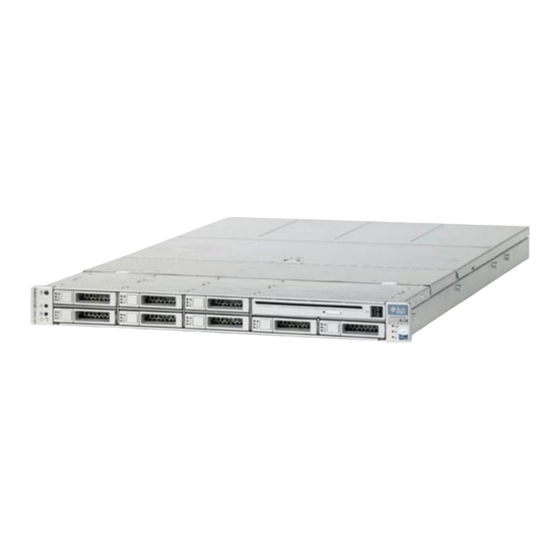
Page 18: Sun Fire X4150 Server Front Panel Features
Sun Fire X4150 Server Front Panel Features shows front panel features on the Sun Fire X4150 Server. FIGURE 1-1 Front Panel Features FIGURE 1-1 Figure Legend Locator LED/Locator button (white) Drives map Service Action Required LED (amber) Power Supply Service Required LED (amber) -
Page 19: Sun Fire X4150 Server Rear Panel Features
Sun Fire X4150 Server Rear Panel Features shows rear panel features on the Sun Fire X4150 Server. For more detailed FIGURE 1-2 information about ports and their uses, see the Sun Fire X4150 Server Installation Guide. Panel Features Rear FIGURE 1-2... -
Page 20: Illustrated Parts Breakdown
Illustrated Parts Breakdown The following illustrations provide exploded views of Sun Fire X4150 Server system components. Use these illustrations, and the accompanying tables, to identify parts in your system. I/O Components (Sun Fire X4150 Server) FIGURE 1-3 Figure Legend Top Cover... - Page 21 Power Distribution/Fan Module Components (Sun Fire X4150 Server) FIGURE 1-4 Figure Legend Power Distribution Board/Bus Bar Assembly Air Baffle Paddle Card Fan Modules Power Supplies Fan Boards Chapter 1 Sun Fire X4150 Server Overview...
- Page 22 Cables 1 (Sun Fire X4150 Server with SATA) FIGURE 1-5 Figure Legend SATA Drive Data Cable Motherboard to Power Distribution Board Cable Top Cover Interlock 1-10 Sun Fire X4150 Server Service Manual • November 2009...
- Page 23 Cables 2 (Sun Fire X4150 Server with SAS) FIGURE 1-6 Figure Legend SAS Drive Data Cable Motherboard to Power Distribution Board Cable Top Cover Interlock Chapter 1 Sun Fire X4150 Server Overview 1-11...
- Page 24 1-12 Sun Fire X4150 Server Service Manual • November 2009...
-
Page 25: Preparing To Service The System
C H A P T E R Preparing to Service the System This chapter describes how to prepare the Sun Fire X4150 Server for servicing. The following topics are covered: Section 2.1, “Safety Information” on page 2-1 ■ Section 2.2, “Required Tools” on page 2-2 ■... -
Page 26: Required Tools
Follow the electrostatic discharge safety practices as described in this chapter. ■ Required Tools The Sun Fire X4150 Server can be serviced with the following tools: Antistatic wrist strap ■ Antistatic mat ■... -
Page 27: Powering Off The Server
Chassis Serial Number Label FIGURE 2-1 Powering Off the Server To remove main power from the server, use one of the methods shown in the following table. Shutdown Procedures TABLE 2-1 Shutdown Method Graceful shutdown Use a pen, or other pointed object, to press and release the Power button on the front panel. -
Page 28: Powering Off The Server Using The Service Processor Command Line
Refer to your application documentation for specific information. 4. Shut down all logical domains. 5. Shut down the Solaris™ Operating System. 6. Open an SSH session. 7. Log into the Service Processor. Sun Fire X4150 Server Service Manual • November 2009... -
Page 29: Extending The Server To The Maintenance Position
8. Type: stop /SYS cd /SP/CtrlInfo set powerctrl=off Extending the Server to the Maintenance Position The following components can be serviced with the server in the maintenance position: Hard drives/SSDs ■ Fan modules ■ Power supplies ■ DVD/USB module ■ Fan power boards ■... -
Page 30: Removing A Server From The Rack
The server must be removed from the rack to service the following components: Motherboard ■ Power distribution board ■ Paddle card ■ Disk cage ■ Drives backplane ■ Front panel light-pipe assemblies ■ Sun Fire X4150 Server Service Manual • November 2009... - Page 31 Caution – If necessary, use two people to dismount and carry the chassis. To remove a server from the rack: 1. Disconnect all the cables and power cords from the server. 2. Extend the server to the maintenance position. Section 2.5, “Extending the Server to the Maintenance Position” on page 2-5.
-
Page 32: Performing Electrostatic Discharge And Antistatic Prevention Measures
5. Set the server on a sturdy work surface. Performing Electrostatic Discharge and Antistatic Prevention Measures 2.7.1 Electrostatic Discharge Safety Measures Electrostatic discharge (ESD) sensitive devices, such as the motherboards, PCI cards, drives, and memory cards, require special handling. Sun Fire X4150 Server Service Manual • November 2009... -
Page 33: Using An Antistatic Wrist Strap
Caution – Circuit boards and drives contain electronic components that are extremely sensitive to static electricity. Ordinary amounts of static electricity from clothing or the work environment can destroy the components located on these boards. Do not touch the components along their connector edges. Caution –... -
Page 34: Removing The Top Cover
3. Lift up and remove the top cover. [3] Caution – If the top cover is removed before the server is powered off, the server will immediately go into Standby mode. 2-10 Sun Fire X4150 Server Service Manual • November 2009... - Page 35 Removing the Sun Fire X4150 Server Top Cover FIGURE 2-6 Chapter 2 Preparing to Service the System 2-11...
- Page 36 2-12 Sun Fire X4150 Server Service Manual • November 2009...
-
Page 37: Servicing Customer Replaceable Devices
C H A P T E R Servicing Customer Replaceable Devices This chapter describes how to replace the hot-swappable and hot-pluggable customer replaceable units (CRUs) in the Sun Fire X4150 Server. The following topics are covered: Section 3.1, “Hot-Pluggable or Hot-Swappable Devices” on page 3-1 ■... -
Page 38: Hot-Pluggable Devices
(for example, mounting a drive). In the Sun Fire X4150 Server, hard drives and SSD drives are hot-pluggable. To hot-plug a drive you must take the drive offline (to prevent any applications from accessing it, and to remove the logical software links to it) before you can safely remove it. -
Page 39: Sun Fire X4150 Server Drive Guidelines
Sun Fire X4150 with on-board controller: Up to 4 SSDs can be installed. ■ Sun Fire X4150 with both HBA and on-board controller: 0 to 4 SSDs can be installed into the system for the X4150. ■ The remaining slots can be filled with up with hard drives that can equal up to 4. -
Page 40: Ssd Minimum Required Firmware
LSI FW: 1.27.02, MPTBIOS: 6.26.00 ■ SSD firmware Intel SSD FW: 845C8626 ■ 3.2.3 Drive Status LED Reference shows the hard drive and SSD LED status indicators. FIGURE 3-2 Drive Status LEDs FIGURE 3-2 Sun Fire X4150 Server Service Manual • November 2009... -
Page 41: Removing A Hard Drive Or Ssd
To remove a drive from a Sun Fire X4150 Server: 1. Identify the drive you wish to remove. The amber Service Required LED might be lit. For specific drive locations, see Section 3.2.1, “Sun Fire X4150 Server Drive Guidelines”... - Page 42 Caution – The latch is not an ejector. Do not bend it too far to the right. Doing so can damage the latch. Locating the Drive Release Button and Latch FIGURE 3-3 Sun Fire X4150 Server Service Manual • November 2009...
-
Page 43: Installing An Hard Drive Or Ssd
3.2.5 Installing an Hard Drive or SSD Installing a hard drive or SSD drive into the Sun Fire X4150 Server is a two-step process. You must first install a drive into the drive slot, and then configure that drive to the server. -
Page 44: Using Drive Fillers
6-6. 3.2.6 Using Drive Fillers All drive slots in the Sun Fire X4150 Server must have drive fillers in place during operation to maintain airflow. To remove fillers, pull the ejector and pull the filler out of the chassis. Servicing Fan Modules The following topics are covered: Section 3.3.1, “About Sun Fire X4150 Server Fans”... -
Page 45: Fan Module Led Reference
3.3.2 Fan Module LED Reference Each fan module contains LEDs that are visible when you open the fan tray access door. describes fan tray module LEDs and their functions. shows TABLE 3-4 FIGURE 3-6 fan tray module LED locations. Fan Module Status LEDs TABLE 3-4 Color Lights when... -
Page 46: Detecting Fan Module Failure
Fan Module Status LEDs FIGURE 3-5 Section 1.2, “Sun Fire X4150 Server Chassis Overview” on page 1-3 for more information about system status LEDs. 3.3.3 Detecting Fan Module Failure The following LEDs are lit when a fan module fault is detected: Front and rear Service Required LEDs ■... -
Page 47: Removing A Fan Module
The system Overtemp LED might be lit if a fan fault causes an increase in system operating temperature. See Section 1.3, “Sun Fire X4150 Server Front Panel Features” on page 1-6 for more information about identifying and interpreting system LEDs. -
Page 48: Installing A Fan Module
1. With the top cover door open, install the replacement fan module into the server FIGURE 3-7 The fan modules are keyed to ensure that they are installed in the correct orientation. 3-12 Sun Fire X4150 Server Service Manual • November 2009... - Page 49 4. Close the top cover door. 5. Verify that the Top Fan LED, Service Required LEDs, and the Locator LED/Locator button are not lit. Section 1.2, “Sun Fire X4150 Server Chassis Overview” on page 1-3 for more information about identifying and interpreting system LEDs.
-
Page 50: Servicing Power Supplies
Servicing Power Supplies Some versions of the Sun Fire X4150 Servers are equipped with redundant hot-swappable power supplies. Redundant power supplies enable you to remove and replace a power supply without shutting the server down, provided that the other power supply is online and working. -
Page 51: Removing A Power Supply
Power Supply Status LEDs FIGURE 3-8 Figure Legend Legend Symbol Color Lights when OK to Remove Green A power supply can be removed safely during a hot–swap operation. Service Required Amber The power supply is faulty. The front and rear panel Service Required LEDs are also lit if the system detects a power supply fault. - Page 52 4. Disconnect the power cord from the faulty power supply. 5. Grasp the power supply handle and press the release latch ( FIGURE 3-10 6. Pull the power supply out of the chassis. 3-16 Sun Fire X4150 Server Service Manual • November 2009...
-
Page 53: Installing A Power Supply
Power Supply Release Handle FIGURE 3-10 3.4.4 Installing a Power Supply 1. If you are installing a second power supply in a one power supply system, remove the filler panel. Grasp the vertical wall, and pull the filler panel straight out. - Page 54 Rear Service Required LED ■ Note – See Section 1.3, “Sun Fire X4150 Server Front Panel Features” on page 1-6 Section 1.4, “Sun Fire X4150 Server Rear Panel Features” on page 1-7 for more information about identifying and interpreting system LEDs.
-
Page 55: Servicing The Dvd/Usb Module
Section 2.7, “Performing Electrostatic Discharge and Antistatic Prevention Measures” on page 2-8. 4. Remove the Sun Fire X4150 Server HD7 hard drive. Section 1.2, “Sun Fire X4150 Server Chassis Overview” on page 1-3 for drives locations. 5. Release the DVD/USB module from the drives backplane (... -
Page 56: Installing The Dvd/Usb Module
1. Slide the DVD/USB module into the front of the chassis until it seats FIGURE 3-13 2. Install the drive you removed during the DVD/USB module removal procedure. 3. Power on the server. Section 6.4, “Powering On the Server” on page 6-6. 3-20 Sun Fire X4150 Server Service Manual • November 2009... - Page 57 Installing the DVD/USB Module FIGURE 3-13 Chapter 3 Servicing Customer Replaceable Devices 3-21...
- Page 58 3-22 Sun Fire X4150 Server Service Manual • November 2009...
-
Page 59: Servicing Motherboard Components
C H A P T E R Servicing Motherboard Components This chapter describes how to replace the motherboard and its components in the Sun Fire X4150 Server. Note – Before performing any of the procedures in this chapter, perform the procedures described in... -
Page 60: Servicing Fb-Dimms
Electrostatic Discharge and Antistatic Prevention Measures” on page 2-8. ▼ To Identify Faulty FB-DIMMs The Sun Fire X4150 Server Service Required LED is lit if the system detects a FB-DIMM fault. To use the rear panel Locator button to identify faulty FB-DIMMs: 1. -
Page 61: Fb-Dimm Guidelines
Remind Button FIGURE 4-1 3. Note the location of faulty FB-DIMMs. Faulty FB-DIMMs are identified with a corresponding amber LED on the motherboard. 4. Ensure that all FB-DIMMs are seated correctly in their slots. If re-seating the FB-DIMM does not fix the problem, remove and replace the faulty FB-DIMM. 4.1.1 FB-DIMM Guidelines Use the FB-DIMM guidelines,... - Page 62 All FB-DIMMs must be the same density (same type). ■ The Sun Fire X4150 Server supports the following configurations, such as: ■ 2 FB-DIMMs (minimum configuration) ■ 4 FB-DIMMs ■ 8 FB-DIMMs ■ 16 FB-DIMMs (fully populated configuration) ■ Any even number of DIMM's is allowed. The DIMMs must be populated in matched pairs.
- Page 63 FB-DIMM Layout FIGURE 4-2 FB-DIMM Branch Number, Channel Number, ILOM Address, and Connector TABLE 4-1 Motherboard FB-DIMM Branch Number Channel Number ILOM Address Connector Branch 0 Channel A /SYS/Memory/DIMM_A0 J1001 /SYS/Memory/DIMM_A1 J1101 /SYS/Memory/DIMM_A2 J1101 /SYS/Memory/DIMM_A3 J1101 Channel B /SYS/Memory/DIMM_B0 J1201 /SYS/Memory/DIMM_B1 J1301 /SYS/Memory/DIMM_B2...
- Page 64 /SYS/Memory/DIMM_C3 J1101 Channel D /SYS/Memory/DIMM_D0 J1201 /SYS/Memory/DIMM_D1 J1301 /SYS/Memory/DIMM_D2 J1301 /SYS/Memory/DIMM_D3 J1301 Note – FB-DIMM names in ILOM messages are displayed with the full name, such /SYS/Memory/DIMM_D0 Memory Organization FIGURE 4-3 Sun Fire X4150 Server Service Manual • November 2009...
-
Page 65: To Remove Fb-Dimms
▼ To Remove FB-DIMMs Caution – Ensure that all power is removed from the server before removing or installing FB-DIMMs. You must disconnect the power cables before performing this procedure. 1. Review Section 4.1.1, “FB-DIMM Guidelines” on page 4-3 for memory configuration information. -
Page 66: To Install Fb-Dimms
2. Ensure that the ejector tabs are in the open position. 3. Line up the replacement FB-DIMM with the connector ( FIGURE 4-5 Align the FB-DIMM notch with the key in the connector. This ensures that the FB-DIMM is oriented correctly. Sun Fire X4150 Server Service Manual • November 2009... - Page 67 4. Push the FB-DIMM into the connector until the ejector tabs lock the FB-DIMM in place. If the FB-DIMM does not easily seat into the connector, verify that the orientation of the FB-DIMM is as shown in . If the orientation is reversed, damage FIGURE 4-5 to the FB-DIMM might occur.
-
Page 68: To Install Additional Fb-Dimms
Verify that the AC Present LED is lit. Section 6.4, “Powering On the Server” on page 6-6. d. Power on the server. Section 6.4, “Powering On the Server” on page 6-6. 4-10 Sun Fire X4150 Server Service Manual • November 2009... -
Page 69: Servicing The Air Baffle
Servicing the Air Baffle You must remove the air baffle when removing and installing the motherboard. Note – This is a customer-replaceable unit. Caution – To prevent the system from overheating, ensure that the air baffle is correctly installed before powering on the server. ▼... -
Page 70: To Install The Air Baffle
Reconnect the power cord (or cords) to the power supply (or supplies). Verify that the AC Present LED is lit. Section 6.4, “Powering On the Server” on page 6-6. 4-12 Sun Fire X4150 Server Service Manual • November 2009... - Page 71 d. Power on the server. Section 6.4, “Powering On the Server” on page 6-6. Installing the Air Baffle FIGURE 4-7 Chapter 4 Servicing Motherboard Components 4-13...
-
Page 72: Servicing Pcie Risers
2. Disconnect any data cables connected to the cards on the PCIe riser being removed. Label the cables to ensure proper connection later. 3. Slide the server out of the rack. Section 2.5, “Extending the Server to the Maintenance Position” on page 2-5. 4-14 Sun Fire X4150 Server Service Manual • November 2009... - Page 73 4. If you are servicing a PCIe card, locate its position in the system. 5. Remove the back panel crossbar. a. Loosen the captive Phillips screw on each end of the back panel crossbar. b. Lift the crossbar up and back to remove it from the chassis. ( FIGURE 4-8 c.
-
Page 74: To Install A Pcie Riser
5. Slide the server into the rack. See Section 6.3, “Returning the Server to the Normal Rack Position” on page 6-5. 6. Connect any data cables you removed to service the PCIe cards. 4-16 Sun Fire X4150 Server Service Manual • November 2009... -
Page 75: Servicing Pcie Cards
Installing a PCIe riser FIGURE 4-10 Servicing PCIe Cards Section 4.4.1, “Sun Fire X4150 Server PCIe Card Guidelines” on page 4-18 PCIe card configuration guidelines. Note – This is a customer-replaceable unit. Caution – This procedure requires that you handle components that are sensitive to static discharge. -
Page 76: Sun Fire X4150 Server Pcie Card Guidelines
1. Locate the PCIe card that you want to remove, and note its corresponding riser board. Section 1.4, “Sun Fire X4150 Server Rear Panel Features” on page 1-7 for more information about PCIe slots and their locations. 2. If necessary, make a note of where the PCIe cards are installed. -
Page 77: To Install Pcie Cards
2. Locate the proper PCIe slot for the card you are replacing. 3. If necessary, review the PCIe Card Guidelines to plan your installation. Section 4.4.1, “Sun Fire X4150 Server PCIe Card Guidelines” on page 4-18 additional information. 4. Remove the PCIe riser board. -
Page 78: Servicing The Battery
If the server fails to maintain the proper time when powered off and not connected to a network, replace the battery. You need a small (No. 1 flat-blade) screwdriver. 4-20 Sun Fire X4150 Server Service Manual • November 2009... -
Page 79: To Remove The Battery
1. Remove PCIe riser 0. “To Remove a PCIe Riser” on page 4-14. Section 4.4.1, “Sun Fire X4150 Server PCIe Card Guidelines” on page 4-18. 2. Using a small (No. 1 flat-blade) screwdriver, press the latch and remove the battery from the motherboard. -
Page 80: To Install The Battery
“Performing Electrostatic Discharge and Antistatic Prevention Measures” on page 2-8. Caution – This procedure requires removing the server from the rack. The server is heavy. Two people are required to remove it from the rack. 4-22 Sun Fire X4150 Server Service Manual • November 2009... -
Page 81: To Remove The Motherboard Assembly
▼ To Remove the Motherboard Assembly You need a thermal grease kit to replace the processors. You must remove a heat sink to replace the motherboard, to access screws. 1. Prepare the server for service. a. Power off the server. Section 2.4, “Powering Off the Server”... - Page 82 12. Lift the motherboard assembly out of the chassis ( FIGURE 4-14 Move the motherboard carefully. 13. Place the motherboard assembly on an antistatic mat. Removing the Motherboard Assembly FIGURE 4-14 4-24 Sun Fire X4150 Server Service Manual • November 2009...
-
Page 83: To Install The Motherboard Assembly
4.6.1 To Install the Motherboard Assembly Caution – This procedure requires that you handle components that are sensitive to static discharge. Static discharges can cause the component failures. To avoid damage, ensure that you follow antistatic practices as described in Section 2.7, “Performing Electrostatic Discharge and Antistatic Prevention Measures”... - Page 84 Verify that the AC Present LED is lit. Section 6.4, “Powering On the Server” on page 6-6. d. Power on the server. Section 6.4, “Powering On the Server” on page 6-6. 4-26 Sun Fire X4150 Server Service Manual • November 2009...
-
Page 85: Servicing Processors
Installing the Motherboard Assembly FIGURE 4-15 Servicing Processors The following topics are covered: “To Detect Processor Failure” on page 4-28 ■ Section 4.7.1, “Removing a Processor” on page 4-29 ■ “To Install a Processor FRU” on page 4-30 ■ “To Install an XOption Processor” on page 4-33 ■... -
Page 86: To Detect Processor Failure
FIGURE 4-16 4.7.1 Removing a Processor To remove a processor. 1. Prepare the server for service. a. Power off the server. Section 2.4, “Powering Off the Server” on page 2-3. 4-28 Sun Fire X4150 Server Service Manual • November 2009... - Page 87 b. Disconnect the power cord (or cords) from the power supply (or supplies). Section 2.4, “Powering Off the Server” on page 2-3. c. Slide the server out of the rack. Section 2.5, “Extending the Server to the Maintenance Position” on page 2-5.
-
Page 88: To Install A Processor Fru
Disconnect the power cord (or cords) from the power supply (or supplies). Section 2.4, “Powering Off the Server” on page 2-3. c. Slide the server out of the rack. Section 2.5, “Extending the Server to the Maintenance Position” on page 2-5. 4-30 Sun Fire X4150 Server Service Manual • November 2009... - Page 89 d. Attach an antistatic wrist strap. Section 2.7, “Performing Electrostatic Discharge and Antistatic Prevention Measures” on page 2-8. e. Remove the top cover. Section 2.8, “Removing the Top Cover” on page 2-10. 2. Remove the heatsink on top of the failed processor. 3.
- Page 90 Verify that the AC Present LED is lit. Section 6.4, “Powering On the Server” on page 6-6. d. Power on the server. Section 6.4, “Powering On the Server” on page 6-6. 4-32 Sun Fire X4150 Server Service Manual • November 2009...
-
Page 91: To Install An Xoption Processor
Installing a Processor (Part 2) FIGURE 4-19 ▼ To Install an XOption Processor To install an XOption processor. 1. Prepare the server for service. a. Power off the server. Section 2.4, “Powering Off the Server” on page 2-3. b. Disconnect the power cord (or cords) from the power supply (or supplies). Section 2.4, “Powering Off the Server”... -
Page 92: Resetting Passwords And Clearing Cmos Nvram
“To Reset a Service Processor Password From the BIOS Screen” on page 4-35 ■ “To Reset a BIOS Password Using a Jumper” on page 4-35 ■ “To Reset CMOS NVRAM Using a Jumper” on page 4-36 ■ 4-34 Sun Fire X4150 Server Service Manual • November 2009... -
Page 93: Overview
4.8.1 Overview Clearing CMOS settings resets the BIOS settings, including the BIOS password. You can reset a password from the BIOS screen or with a jumper. You can also clear the NVRAM or BIOS Password by changing the J23 jumper position as follows. J23 jumper position 1-3: Clears CMOS NVRAM J23 jumper position 2-4: Clears the Password Access the 6-pin J23 jumper on the motherboard, located near the CR-2032 battery,... -
Page 94: To Reset Cmos Nvram Using A Jumper
Section 2.4, “Powering Off the Server” on page 2-3. 2. Disconnect the power cord (or cords) from the power supply (or supplies). Section 2.4, “Powering Off the Server” on page 2-3. 4-36 Sun Fire X4150 Server Service Manual • November 2009... -
Page 95: Recovering From Corrupt Service Processor Software
3. Extend the server into the maintenance position. Section 2.5, “Extending the Server to the Maintenance Position” on page 2-5. 4. Attach an antistatic wrist strap. Section 2.7, “Performing Electrostatic Discharge and Antistatic Prevention Measures” on page 2-8. 5. Remove the top cover. Section 2.8, “Removing the Top Cover”... - Page 96 JP16 is located toward the rear of the board, between Riser 1 and Riser 2. 9. Insert a bootable flash drive into a USB port. 10. Connect AC power cables. Section 6.4, “Powering On the Server” on page 6-6. 4-38 Sun Fire X4150 Server Service Manual • November 2009...
- Page 97 11. Power on the server. Section 6.4, “Powering On the Server” on page 6-6. A message appears stating that the BMC was not found. The server takes up to three minutes to boot. 12. Press F2 to enter system BIOS and verify that the Flash device is in the boot order.
- Page 98 4-40 Sun Fire X4150 Server Service Manual • November 2009...
-
Page 99: Servicing Infrastructure Boards And Components
C H A P T E R Servicing Infrastructure Boards and Components This chapter describes how to replace cold-swappable, field-replaceable units (FRUs) in the Sun Fire X4150 Server. The following topics are covered: Section 5.1, “Servicing the Fan Power Boards” on page 5-1 (FRU) ■... -
Page 100: Removing A Fan Power Board
Note – If you are replacing a defective fan power board, remove only the fan modules that are necessary to remove the defective fan power board. Section 3.3.4, “Removing a Fan Module” on page 3-11. Sun Fire X4150 Server Service Manual • November 2009... -
Page 101: Installing A Fan Power Board
3. Remove the Phillips screw that secures the fan power board to the chassis FIGURE 5-1 4. Slide the fan power board to the left to disengage it from the paddle card. 5. Remove the fan power board from the system and place it on an antistatic mat. Removing the Fan Power Board FIGURE 5-1 5.1.2... - Page 102 Verify that the AC Present LED is lit. Section 6.4, “Powering On the Server” on page 6-6. d. Power on the server. Section 6.4, “Powering On the Server” on page 6-6. Sun Fire X4150 Server Service Manual • November 2009...
-
Page 103: Servicing The Drives Cage
Servicing the Drives Cage You must remove the drives cage to access the following components: Drives backplane ■ Front control panel light pipe assemblies ■ Note – FRU: This field-replaceable unit should be replaced only by qualified service technicians. Contact your Sun Service representative for assistance. Caution –... - Page 104 7. Lift the drives cage up and disconnect the drive data cables ( [4]). FIGURE 5-3 Press the connector release button to release the cable. 8. Set the drives cage on an antistatic mat. Sun Fire X4150 Server Service Manual • November 2009...
-
Page 105: Installing The Drives Cage
Removing the Drives Cage FIGURE 5-3 5.2.2 Installing the Drives Cage 1. Connect the drive data cables. Press the connector into its socket until it snaps into place. 2. Position the drive cage in the chassis, over its standoffs ( [1]). - Page 106 [3]). FIGURE 5-4 Two screws secure the disk cage to each side of the chassis. 5. Install the fan power boards. Section 5.1.2, “Installing a Fan Power Board” on page 5-3. Sun Fire X4150 Server Service Manual • November 2009...
-
Page 107: Servicing The Drives Backplane
6. Install the fan modules. Section 3.3.5, “Installing a Fan Module” on page 3-12 7. Install the top cover. Section 6.1, “Installing the Top Cover” on page 6-2. 8. Install the server into the rack. Section 6.2, “Reinstalling the Server in the Rack” on page 6-3. -
Page 108: Installing The Drives Backplane
2. Install the two No. 2 Phillips screws that secure the backplane to the drives cage. 3. Install the drives cage. Section 5.2.2, “Installing the Drives Cage” on page 5-7. 5-10 Sun Fire X4150 Server Service Manual • November 2009... -
Page 109: Servicing The Front Control Panel Light Pipe Assembly
Installing the Drives Backplane FIGURE 5-6 Servicing the Front Control Panel Light Pipe Assembly You must remove the drives cage and backplane to service the front control panel light pipe assemblies. Note – FRU: This field-replaceable unit should be replaced only by qualified service technicians. -
Page 110: Removing The Front Control Panel Light Pipe Assembly
3. Remove the two No. 2 Phillips screws securing the front control panel light pipe assembly to the drives cage ( FIGURE 5-7 4. Slide the light pipe assembly out of the drives cage. Removing the Light Pipe Assembly FIGURE 5-7 5-12 Sun Fire X4150 Server Service Manual • November 2009... -
Page 111: Installing The Front Control Panel Light Pipe Assembly
5.4.2 Installing the Front Control Panel Light Pipe Assembly 1. Align the light pipe assembly with the mounting holes on the drives cage. 2. Secure the light pipe assembly with two No. 2 Phillips screws. 3. Install the drives backplane. Section 5.3.1, “Removing the Drives Backplane”... - Page 112 5. Grasp the bus bar and pull the PDB/bus bar assembly to the left, away from the paddle card. 6. Lift the PDB/bus bar assembly up and out of the system. 7. Place the PDB/bus bar assembly on an antistatic mat. 5-14 Sun Fire X4150 Server Service Manual • November 2009...
-
Page 113: Installing The Power Distribution Board
Removing the Power Distribution Board FIGURE 5-8 5.5.2 Installing the Power Distribution Board 1. Lower the PDB/bus bar assembly into the chassis ( FIGURE 5-9 The PDB fits over a series of mushroom standoffs in the floor of the chassis. 2. -
Page 114: Servicing The Paddle Card
The paddle card assembly includes the top cover interlock switch. Note – FRU: This field-replaceable unit should be replaced only by qualified service technicians. Contact your Sun Service representative for assistance. 5-16 Sun Fire X4150 Server Service Manual • November 2009... -
Page 115: Removing The Paddle Card
5. Slide the paddle card back, away from its connector on the drives backplane. 6. Lift the paddle card up and out of the chassis. 7. Place the paddle card on an antistatic mat. Removing the Paddle Card (Sun Fire X4150 Server) FIGURE 5-10 5.6.2 Installing the Paddle Card 1. -
Page 116: Servicing Cables
Section 5.7.4, “Installing Drive Cables in a SATA Configuration” on page 5-24 ■ Section 5.7.5, “Changing Drive Cables from SAS to SATA” on page 5-26 ■ Section 5.7.6, “Change Drive Cables from SATA to SAS” on page 5-27 ■ 5-18 Sun Fire X4150 Server Service Manual • November 2009... -
Page 117: Removing Drive Cables In A Sas Configuration
Section 5.7.7, “Converting From SAS Configuration To SSD Configuration” on ■ page 5-27 Section 5.7.8, “Removing a PDB Cable” on page 5-28 ■ Section 5.7.9, “Installing a PDB Cable” on page 5-30 ■ Section 1.5, “Illustrated Parts Breakdown” on page 1-8 for illustrations of cables. -
Page 118: Installing Drives Cables In A Sas Configuration
A right angle connector is on one end and a single connector is on the other end. a. Install right angle connector in drives backplane. The connector is on the left from the front of the unit. 5-20 Sun Fire X4150 Server Service Manual • November 2009... - Page 119 b. Route the cable down and in front of fan board 0, to prevent the cable from blocking the air stream. Lay the cable through the opening in the midwall, opposite the other disk backplane connector. c. Plug the connector into the connector on the HBA card that is closest to the gold fingers (port 0).
-
Page 120: Removing Drive Cables In A Sata Configuration
Disconnect the power cord (or cords) from the power supply (or supplies). Section 2.4, “Powering Off the Server” on page 2-3. c. Slide the server out of the rack. Section 2.5, “Extending the Server to the Maintenance Position” on page 2-5. 5-22 Sun Fire X4150 Server Service Manual • November 2009... - Page 121 d. Remove the top cover. Section 2.8, “Removing the Top Cover” on page 2-10. e. Attach an antistatic wrist strap. Section 2.7, “Performing Electrostatic Discharge and Antistatic Prevention Measures” on page 2-8. 2. Remove the card in the PCIe 0 riser for better access (Optional). 3.
-
Page 122: Installing Drive Cables In A Sata Configuration
The disk 0-3 cable has a right angle connector on one end and a single connector on the other end. a. Install the right angle connector in the drives backplane. The connector is on the left from the front of the server. 5-24 Sun Fire X4150 Server Service Manual • November 2009... - Page 123 b. Route the cable down in front of fan board 0 to prevent it from blocking the air stream. Lay it through the opening in the midwall opposite the other disk backplane connector. c. Plug the connector into the connector on the motherboard. 2.
-
Page 124: Changing Drive Cables From Sas To Sata
3. Install either a different HBA card or a PCIe filler in PCIe slot 1. 4. Install the new cables in the SATA configuration. Section 5.7.4, “Installing Drive Cables in a SATA Configuration” on page 5-24. 5-26 Sun Fire X4150 Server Service Manual • November 2009... -
Page 125: Change Drive Cables From Sata To Sas
5.7.6 Change Drive Cables from SATA to SAS To change drives cables from SATA to SAS. 1. Remove the cables in the SATA configuration. Section 5.7.3, “Removing Drive Cables in a SATA Configuration” on page 5-22. 2. Install the SAS HBA card in PCIe slot 1 (middle slot). 3. -
Page 126: Removing A Pdb Cable
Grasp each end of the connector on the motherboard, and then pull straight up to disconnect from connector. Caution – Do not to bend the pins on the unshrouded motherboard connector. 5-28 Sun Fire X4150 Server Service Manual • November 2009... - Page 127 Removing a PDB Cable FIGURE 5-16 Chapter 5 Servicing Infrastructure Boards and Components 5-29...
-
Page 128: Installing A Pdb Cable
Verify that the AC Present LED is lit. Section 6.4, “Powering On the Server” on page 6-6. d. Power on the server. Section 6.4, “Powering On the Server” on page 6-6. 5-30 Sun Fire X4150 Server Service Manual • November 2009... - Page 129 Installing a PDB Cable FIGURE 5-17 Chapter 5 Servicing Infrastructure Boards and Components 5-31...
- Page 130 5-32 Sun Fire X4150 Server Service Manual • November 2009...
-
Page 131: Returning The Server To Operation
C H A P T E R Returning the Server to Operation This chapter describes how to return the Sun Fire X4150 Server to operation after you have performed service procedures. The following topics are covered in this chapter: Section 6.1, “Installing the Top Cover” on page 6-2 ■... -
Page 132: Installing The Top Cover
Set the cover down so that it hangs over the rear of the server by about an inch (25.4 mm). 2. Slide the top cover forward until it seats ( FIGURE 6-1 3. Close the fan cover. Installing the Top Cover FIGURE 6-1 Sun Fire X4150 Server Service Manual • November 2009... -
Page 133: Reinstalling The Server In The Rack
Reinstalling the Server in the Rack If you removed the server chassis from the rack, perform these steps. Caution – The servers are heavy. Two people might be required to carry the chassis and install it in the rack. 1. On the rack, ensure that the slide rails are extended. 2. - Page 134 Returning the Server to the Rack FIGURE 6-2 Sun Fire X4150 Server Service Manual • November 2009...
-
Page 135: Returning The Server To The Normal Rack Position
Returning the Server to the Normal Rack Position If you extended the server to the maintenance position, use this procedure to return the server to the normal rack position. 1. Release the slide rails from the fully extended position by pushing the release tabs on the side of each rail ( FIGURE 6-3 Release Tabs on Rails... -
Page 136: Powering On The Server
Powering On the Server Before powering on your server for the first time, follow the installation and cabling instructions provided in the Sun Fire X4150 Server Installation Guide, which is shipped with the system and is also available online. To connect power cords and apply power to the server: 1. - Page 137 Power/OK LED Front Panel FIGURE 6-5 Chapter 6 Returning the Server to Operation...
- Page 138 Sun Fire X4150 Server Service Manual • November 2009...
-
Page 139: Connector Pinouts
A P P E N D I X Connector Pinouts This appendix provides reference information about the Sun Fire X4150 Server back panel ports and pin assignments. Topics covered in this appendix include: Section A.1, “Serial Management Port Connector” on page A-2 ■... -
Page 140: Serial Management Port Connector
Serial Management Connector Diagram FIGURE A-2 Serial Management connector signals TABLE A-1 Signal Description Signal Description Request to Send Ground Data Terminal Ready Receive Data Transmit Data Data Set Ready Ground Clear to Send Sun Fire X4150 Server Service Manual • November 2009... -
Page 141: Network Management Port Connector
Network Management Port Connector The network management connector (labeled NET MGT) is an RJ-45 connector located on the motherboard and can be accessed from the back panel. This port needs to be configured prior to use. Network Management Connector Diagram FIGURE A-3 Network Management connector signals TABLE A-2... -
Page 142: Video Connector
Sync Ground Blue Video Monitor ID - Bit 1 Monitor ID - Bit 2 Monitor ID - Bit 0 Ground Horizontal Sync Red Ground Vertical Sync Green Ground N/C (Reserved) Blue Ground Sun Fire X4150 Server Service Manual • November 2009... -
Page 143: Usb Connectors
USB Connectors Two Universal Serial Bus (USB) ports are located on the motherboard in a double- stacked layout and can be accessed from the back panel. USB Connector Diagram FIGURE A-5 USB Connector Signals TABLE A-4 Signal Description Signal Description +5 V (fused) +5 V (fused) USB0/1-... -
Page 144: Gigabit Ethernet Connectors
Transmit/Receive Data 0 + Transmit/Receive Data 2 – Transmit/Receive Data 0 – Transmit/Receive Data 1 – Transmit/Receive Data 1 + Transmit/Receive Data 3 + Transmit/Receive Data 2 + Transmit/Receive Data 3 – Sun Fire X4150 Server Service Manual • November 2009... -
Page 145: Bios Power-On Self-Test (Post) Codes
A P P E N D I X BIOS Power-On Self-Test (POST) Codes The system BIOS provides a basic power-on self-test (POST), during which the BIOS checks the basic devices required for the server to operate. The progress of the self- test is indicated by a series of POST codes. -
Page 146: How Bios Post Memory Testing Works
4. Initialize the BIOS Setup Utility by pressing the F2 key while the system is performing the power-on self-test (POST). The BIOS Main Menu screen appears. 5. Select Server. The Server screen appears. 6. Select AST2000 LAN Configuration. The LAN Configuration screen appears. Sun Fire X4150 Server Service Manual • November 2009... -
Page 147: Changing Post Options
7. Select the IP Address menu item. The SP’s IP address appears 8. Start a web browser and type the SP’s IP address in the browser’s address bar. 9. Type a user name and password as follows: User name: root Password: changeme 10. -
Page 148: Post Codes
Pause – The message appears on the screen, an error is logged to the SEL, and user ■ input is required to continue. The user can take immediate corrective action or choose to continue booting. Sun Fire X4150 Server Service Manual • November 2009... - Page 149 Halt – The message appears on the screen, an error is logged to the SEL, and the ■ system cannot boot unless the error is resolved. The user needs to replace the faulty part and restart the system. Error Messages and Responses TABLE B-1 Error Code...
- Page 150 Processor Failed BIST Pause 0155 Processor Failed BIST Pause 0156 Processor Failed BIST Pause 0157 Processor Failed BIST Pause 0158 Processor Failed BIST Continues to boot 0159 Processor Failed BIST Continues to boot Sun Fire X4150 Server Service Manual • November 2009...
- Page 151 Error Messages and Responses (Continued) TABLE B-1 Error Code Error Message Response 015A Processor Failed BIST Continues to boot 015B Processor Failed BIST Continues to boot 015C Processor Failed BIST Continues to boot 015D Processor Failed BIST Continues to boot 015E Processor Failed BIST Continues to boot...
- Page 152 Unsupported Memory Vendor : DIMM_C0 Warning 5189 Unsupported Memory Vendor : DIMM_C1 Warning 518A Unsupported Memory Vendor : DIMM_C2 Warning 518B Unsupported Memory Vendor : DIMM_C3 Warning 518C Unsupported Memory Vendor : DIMM_D0 Warning Sun Fire X4150 Server Service Manual • November 2009...
- Page 153 Error Messages and Responses (Continued) TABLE B-1 Error Code Error Message Response 518D Unsupported Memory Vendor : DIMM_D1 Warning 518E Unsupported Memory Vendor : DIMM_D2 Warning 518F Unsupported Memory Vendor : DIMM_D3 Warning 5190 Unsupported AMB Vendor : DIMM_A0 Warning 5191 Unsupported AMB Vendor : DIMM_A1 Warning...
- Page 154 Continues to boot available. 8601 Error: BMC Not Responding Continues to boot 8701 Insufficient Runtime space for MPS data.!!. Continues to boot System may operate in PIC or Non-MPS mode. B-10 Sun Fire X4150 Server Service Manual • November 2009...
-
Page 155: Bios Screens
This section describes how to view and/or modify the BIOS Setup Utility screens in . The BIOS Setup utility reports system information and can Sun Fire X4150 Server be used to configure the server BIOS settings. The Basic Input/Output System (BIOS) has a Setup utility stored in the BIOS flash memory. -
Page 156: Bios Setup Screens Overview
Advanced Menu Screens” on computing, USB, PCI, MPS and other page C-7 information. Boot Configure the boot device priority (drives Section C.2.3, “BIOS Boot and the DVD-ROM drive). Menu Screens” on page C-15 Sun Fire X4150 Server Service Manual • November 2009... - Page 157 BIOS Setup Screens Summary TABLE C-1 Screen Description See... Server Server devices can be configured by the Section C.2.4, “BIOS Server BIOS (if applicable). Menu Screens” on page C-19 Security Set or change the user and supervisor Section C.2.5, “BIOS Security passwords.
- Page 158 BIOS Utility Menu Tree FIGURE C-1 Sun Fire X4150 Server Service Manual • November 2009...
-
Page 159: Bios Setup Menu Screens
The following figures show sample BIOS Setup Utility screens. Sun Fire X4150 Server Note – The screens shown are examples. The version numbers and the screen items and selections shown are subject to change over the life of the product. - Page 160 BIOS Setup Utility: Main - System Overview FIGURE C-2 BIOS Setup Utility: Main- Product Information (Access at Bottom) FIGURE C-3 Sun Fire X4150 Server Service Manual • November 2009...
-
Page 161: Bios Advanced Menu Screens
BIOS Advanced Menu Screens The BIOS Advanced screens provide detailed configuration information for the CPU, memory, IDE, Super IO, trusted computing, USB, PCI, MPS and other system information. has the following BIOS Advanced screens: Sun Fire X4150 Server Appendix C BIOS Screens... - Page 162 BIOS Setup Utility: Advanced FIGURE C-5 BIOS Setup Utility: Advanced- CPU Settings FIGURE C-6 Sun Fire X4150 Server Service Manual • November 2009...
- Page 163 BIOS Setup Utility: Advanced - System Memory Settings FIGURE C-7 Advanced System Memory Settings: MCH Branch Mode [Branch Interleave]—Choose one of the following settings: Rank interleave—Interleaves in the same branch. Branch interleave—Interleaves between branch 0 and 1. Mirroring—Mirrors branch space between branches. Appendix C BIOS Screens...
- Page 164 BIOS Setup Utility: Advanced- IDE Configuration FIGURE C-8 BIOS Setup Utility: Advanced- Super IO Configuration FIGURE C-9 C-10 Sun Fire X4150 Server Service Manual • November 2009...
- Page 165 BIOS Setup Utility: Advanced- Trusted Computing FIGURE C-10 BIOS Setup Utility: Advanced- USB Configuration FIGURE C-11 Appendix C BIOS Screens C-11...
- Page 166 BIOS Setup Utility: Advanced- USB Configuration 2 FIGURE C-12 BIOS Setup Utility: Advanced- PCI Configuration FIGURE C-13 C-12 Sun Fire X4150 Server Service Manual • November 2009...
- Page 167 BIOS Setup Utility: Advanced- MPS Configuration FIGURE C-14 BIOS Setup Utility: Advanced - Event Logging Details FIGURE C-15 Appendix C BIOS Screens C-13...
- Page 168 BIOS Setup Utility: Advanced - View Event Log FIGURE C-16 BIOS Setup Utility: Advanced - Event Log - Mark Events As Read FIGURE C-17 C-14 Sun Fire X4150 Server Service Manual • November 2009...
-
Page 169: Bios Boot Menu Screens
FIGURE C-18 C.2.3 BIOS Boot Menu Screens The BIOS Boot screens allow you to configure the boot device priority (drives and the DVD-ROM drive). The Sun Fire X4150 Server has the following BIOS Boot screens. Appendix C BIOS Screens C-15... - Page 170 BIOS Setup Utility: Boot FIGURE C-19 BIOS Setup Utility: Boot Settings Configuration FIGURE C-20 C-16 Sun Fire X4150 Server Service Manual • November 2009...
- Page 171 BIOS Setup Utility: Boot Device Priority FIGURE C-21 BIOS Setup Utility: Boot Hard Drives FIGURE C-22 Appendix C BIOS Screens C-17...
- Page 172 BIOS Setup Utility: Boot CD/DVD Drives FIGURE C-23 C-18 Sun Fire X4150 Server Service Manual • November 2009...
-
Page 173: Bios Server Menu Screens
Service Processor (SP) System Event Logs (SEL) Note – The term BMC that may be displayed on some screens refers to the SP (service processor). has the following BIOS Server screens. Sun Fire X4150 Server BIOS Setup Utility: Server FIGURE C-24 Appendix C... - Page 174 BIOS Setup Utility: Server - Bottom of Scroll FIGURE C-25 BIOS Setup Utility: Server - LAN Configuration FIGURE C-26 C-20 Sun Fire X4150 Server Service Manual • November 2009...
- Page 175 BIOS Setup Utility: Server - LAN Configuration - IP Address Configuration FIGURE C-27 BIOS Setup Utility: Server - Gateway Address Configuration FIGURE C-28 Appendix C BIOS Screens C-21...
- Page 176 BIOS Setup Utility: Server - MAC Address Configuration FIGURE C-29 BIOS Setup Utility: Server - Subnet Mask Configuration FIGURE C-30 C-22 Sun Fire X4150 Server Service Manual • November 2009...
- Page 177 BIOS Setup Utility: Server - View Service Processor (SP) System Event Log FIGURE C-31 (SEL) BIOS Setup Utility: Server - Clear Service Processor (SP) System Event Log FIGURE C-32 (SEL) Appendix C BIOS Screens C-23...
-
Page 178: Bios Security Menu Screens
C.2.5 BIOS Security Menu Screens The BIOS Security screens allow you to set or change the user and supervisor passwords. Sun Fire X4150 Server has the following BIOS Security screens: C-24 Sun Fire X4150 Server Service Manual • November 2009... - Page 179 BIOS Setup Utility: Security FIGURE C-34 BIOS Setup Utility: Security - Change Supervisor Password FIGURE C-35 Appendix C BIOS Screens C-25...
-
Page 180: Bios Exit Menu Screens
The BIOS Exit screens allow you to save changes and exit, discard changes and exit, discard changes, or load optimal or fail-safe defaults. has the following BIOS Exit screens: Sun Fire X4150 Server C-26 Sun Fire X4150 Server Service Manual • November 2009... - Page 181 BIOS Setup Utility: Exit FIGURE C-37 BIOS Setup Utility: Exit - Save Configuration Changes FIGURE C-38 Appendix C BIOS Screens C-27...
- Page 182 BIOS Setup Utility: Exit - Discard Changes FIGURE C-39 BIOS Setup Utility: Exit - Discard Changes, Do Not Exit FIGURE C-40 C-28 Sun Fire X4150 Server Service Manual • November 2009...
- Page 183 BIOS Setup Utility: Exit - Load Optimal Defaults FIGURE C-41 BIOS Setup Utility: Exit - Load Fail-safe Defaults FIGURE C-42 Appendix C BIOS Screens C-29...
- Page 184 C-30 Sun Fire X4150 Server Service Manual • November 2009...
- Page 185 Index drive addressing, 3-7 antistatic mat, 2-9 release button, 3-6 antistatic wrist strap, 2-8, 2-9 drive fillers, 3-8 drives location, 3-6 BIOS drives backplane changing menu settings, C-1 installing, 5-10 configuring, C-1 removing, 5-9 overview, C-1 DVD/USB module POST codes, B-4 installing, 3-20 POST options, B-3 removing, 3-19...
- Page 186 B-3 codes table, B-4 overview, B-1 redirecting console output, B-2 Power Supply Faliure LED, 3-14, 4-28 powering off server from service processor prompt, 2-4 service processor command, 2-4 Index-2 Sun Fire X4150 Server Service Manual • November 2009...
Need help?
Do you have a question about the Sun Fire X4150 and is the answer not in the manual?
Questions and answers