Sun Microsystems Sun Fire X4150 Installation Manual
Hide thumbs
Also See for Sun Fire X4150:
- Service manual (186 pages) ,
- Administration manual (150 pages) ,
- Installation manual (107 pages)

Subscribe to Our Youtube Channel
Related Manuals for Sun Microsystems Sun Fire X4150


Summary of Contents for Sun Microsystems Sun Fire X4150
- Page 1 Sun Fire X4150 Server ™ Installation Guide Sun Microsystems, Inc. www.sun.com Part No. 820-1851-12 May 2009, Revision A Submit comments about this document at: http://www.sun.com/hwdocs/feedback...
- Page 2 Cette distribution peut des éléments développés par des tiers. Sun, Sun Microsystems, le logo Sun, Java, Netra, Solaris, StarOffice, Sun Ray, Galaxy Sun Fire X et le logo SunSpectrum Pac (Sunburst design) sont des marques de fabrique ou des marques déposées de Sun Microsystems, Inc.
-
Page 3: Table Of Contents
Contents Preface vii Before You Begin 1 Tools and Equipment Needed 1 Installation Process Flowchart 1 Unpacking the Boxes 4 Package Contents Inventory 4 Options 4 Antistatic Precautions 5 Sun Fire X4150 Server Description 6 Front Panel Features 6 Back Panel 7 Installing the Sun Fire X4150 Server Into a Rack with Slide-Rails 9 Before You Install the Server 9 Server Installation Process Overview 9... - Page 4 Installing the Mounting-Brackets Onto the Server 13 Attaching the Slide-Rail Assemblies to the Rack 14 Installing the Server Into the Slide-Rail Assemblies 17 Installing the Cable Management Arm 19 Verifying Operation of the Slide-rails and CMA 26 Setting Up the Sun Fire X4150 Server 27 Connecting the Cables 28 Connector Locations 28 Cabling the Server 29...
- Page 5 Installation Worksheet 47 Configuring the Solaris OS 49 Redirect the Console Output to the Video Port (Optional) 50 Using the GRUB Menu 50 Configuring Sun Fire X4150 Server RAID Drives 51 RAID Drive Overview 51 RAID Drive Options 52 Mirroring the Preinstalled Solaris OS with LSI RAID 53 Creating a RAID Set to Incorporate a Preinstalled OS Using the Sun StorageTek Card 54 Solaris 10 Operating System User Information 55...
- Page 6 Power On the Main Power 65 Power Off from Main Power Mode 66 Setup Troubleshooting 67 Contacting Support 68 Sun Fire X4150 Server Installation Guide • May 2009...
-
Page 7: Preface
Preface The Sun Fire X4150 Server Installation Guide provides detailed information about how to install the Sun Fire X4150™ server hardware and software. This book is intended for system administrators, network administrators, and service technicians who have an understanding of server systems. How This Book Is Organized This guide contains the following chapters: Installation Guide Chapters... -
Page 8: Typographic Conventions
Typographic Conventions Typeface Meaning Examples The names of commands, files, Edit your.login file. AaBbCc123 and directories; onscreen Use ls -a to list all files. computer output % You have mail. What you type, when contrasted AaBbCc123 with onscreen computer output Password: AaBbCc123 Book titles, new words or terms,... -
Page 9: Related Documentation
Sun Fire X4150 Server Documentation To view the latest Sun Fire X4150 server documentation online, go to , and then navigate to Sun Fire X4150 server documentation. http://docs.sun.com Related Documentation A Where To Find Documentation sheet lists available documents for the Sun Fire X4150 server and describes the Sun Fire X4150 server document set. -
Page 10: Sun Welcomes Your Comments
Sun Welcomes Your Comments Sun is interested in improving its documentation and welcomes your comments and suggestions. You can submit your comments by going to: http://www.sun.com/hwdocs/feedback/ Please include the title and part number of your document with your feedback. The part number of this Sun Fire X4150 Server Installation Guide is 820-1851-12. -
Page 11: Before You Begin
C H A P T E R Before You Begin This chapter describes how to set up the Sun Fire X4150 server hardware. It includes the following topics: “Tools and Equipment Needed” on page 1 ■ “Installation Process Flowchart” on page 1 ■... - Page 12 Sun Fire X4150 Server Installation Process (Part 1) FIGURE 1-1 See: “Unpacking the Boxes” on page 4 Sun Fire X4150 Server Service Manual “Preparing the Slide Rails and Server for Installation” on page 11 .“Installing the Server Into the Slide-Rail Assemblies”...
- Page 13 Sun Fire X4150 Server Installation Process (Part 2) FIGURE 1-2 See: Sun Fire X4150, X4250, and X4450 Server Operating System Installation Guide “Configuring the Preinstalled Solaris 10 Operating System” on page 45 “Configuring the Preinstalled Windows Server 2003 R2 Operating System” on page 57 Note: The preinstalled image can only convert to a 2-disk mirror RAID.
-
Page 14: Unpacking The Boxes
Unpacking the Boxes Unpack all server components from the packing cartons. Package Contents Inventory Sun Fire X4150 server ■ Sun Fire X4150 server accessory kit, including the following documentation: ■ Sun Fire X4150, X4250, and X4450 Servers Getting Started Guide ■... -
Page 15: Antistatic Precautions
Antistatic Precautions Electronic equipment is susceptible to damage by static electricity. Use a grounded antistatic wriststrap, footstrap, or equivalent safety equipment to prevent electrostatic damage (ESD) when you install or service the server. Caution – To protect electronic components from electrostatic damage, which can permanently disable the system or require repair by Sun service technicians, place components on an antistatic surface, such as an antistatic discharge mat, an antistatic bag, or a disposable antistatic mat. -
Page 16: Sun Fire X4150 Server Description
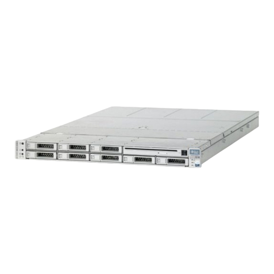
Sun Fire X4150 Server Description This section shows the front and back of the Sun Fire X4150 server. Front Panel Features shows the front panel. the front panel describes features. FIGURE 1-3 TABLE 1-1 Front Panel - 8 drive configuration shown FIGURE 1-3 Front Panel Legend TABLE 1-1... -
Page 17: Back Panel
Back Panel shows the back panel describes the back panel features. FIGURE 1-4 TABLE 1-2 Back Panel FIGURE 1-4 Back Panel Legend TABLE 1-2 Label Item Label Item Power supply unit 0 connector PCI-express slot (0) Power supply unit 0 status indicator LEDs PCI-express slot (1) •... - Page 18 Sun Fire X4150 Server Installation Guide • May 2009...
-
Page 19: Installing The Sun Fire X4150 Server Into A Rack With Slide-Rails
C H A P T E R Installing the Sun Fire X4150 Server Into a Rack with Slide-Rails This chapter describes how to place the Sun Fire X4150 server into a rack using the rail assembly in the rackmount kit. Perform this procedure if the rail assembly is purchased. -
Page 20: Service Label
“Checking Compatibility” on page 10 “Disassembling Slide-Rails” on page 11 “Installing the Mounting-Brackets Onto the Server” on page 13 “Installing the Cable Management Arm” on page 19 “Verifying Operation of the Slide-rails and CMA” on page 26 “Connecting the Cables” on page 28 Rail Assemblies The server might include either tool-less or bolt-on rail assemblies in rackmount kits. -
Page 21: Preparing The Slide Rails And Server For Installation
Rack Compatibility TABLE 2-1 Item Requirement Clearance depth behind front Distance to rear cabinet door is at least 800 mm (31.5 mounting plane inches) with the cable management arm, or 700 mm (27.5 inches), without the cable management arm. Clearance width between front and Distance between structural supports and cable rear mounting planes troughs is at least 456 mm (18 inches). - Page 22 Disassembling Bolt-On Slide-Rails To remove the mounting-brackets from the bolt-on slide-rail assemblies: 1. Unpack the slide-rails. 2. Locate the slide-rail lock at the front of one of the slide-rail assemblies, as shown in FIGURE 2-1 3. Squeeze and hold the tabs at the top and bottom of the lock while you pull the mounting-bracket out of the slide-rail assembly until it reaches the stop.
-
Page 23: Installing The Mounting-Brackets Onto The Server
Installing the Mounting-Brackets Onto the Server To install the mounting-brackets onto the sides of the server: 1. Position a mounting-bracket against the chassis so that the slide-rail lock is at the server front, and the three keyed openings on the mounting-bracket are aligned with the three locating pins on the side of the chassis. -
Page 24: Attaching The Slide-Rail Assemblies To The Rack
Attaching the Slide-Rail Assemblies to the Rack Do one of the following procedures to attach the slide-rail assemblies to the rack: “Disassembling Bolt-On Slide-Rails” on page 12 ■ “Disassembling Tool-less Slide-Rails” on page 12 ■ Attaching Bolt-On Slide-Rail Assemblies To attach bolt-on slide-rail assemblies to the rack: 1. - Page 25 Slide-Rail Assembly Mounting to Rack Post FIGURE 2-3 Slide-rail assembly Rack post Slide-rail assembly bracket on outside of rack post Step 1 Step 2 3. Repeat for the remaining slide-rail assembly. 4. From the front of the rack, set the proper width of the rails with the spacer. (See FIGURE 2-4 Chapter 2 Installing the Sun Fire X4150 Server Into a Rack with Slide-Rails...
- Page 26 Setting the Rail Width FIGURE 2-4 Rail-width spacer 5. Tighten the screws on the brackets. 6. Remove the spacer and confirm that the rails are attached tightly to the rack. 7. Repeat Step 4 through Step 6 for rear of the rack. Sun Fire X4150 Server Installation Guide •...
-
Page 27: Installing The Server Into The Slide-Rail Assemblies
8. If available, extend the anti-tip foot at the bottom of the rack. (See FIGURE 2-5 Extending the Anti-tip Foot FIGURE 2-5 Caution – If your rack does not have an anti-tip foot, the rack could tip over. Attaching Tool-less Slide-Rail Assemblies To attach tool-less slide-rail assemblies to the rack, refer to the install card instructions included with the kit. - Page 28 Caution – Always load equipment into a rack from the bottom up so that it will not become top-heavy and tip over. Extend your rack’s anti-tip foot to prevent the rack from tipping during equipment installation. 1. Push the slide-rails into the slide-rail assemblies in the rack as far as possible. 2.
-
Page 29: Installing The Cable Management Arm
4. Simultaneously push and hold the slide-rail release buttons on each mounting- bracket while you push the server into the rack. (See .) Continue FIGURE 2-6 pushing until the slide-rail locks on the front of the mounting-brackets engage the slide-rail assemblies. You will hear an audible click. - Page 30 3. Remove tape to separate parts. The CMA rail extension might be taped to the CMA arm. 4. Attach the CMA rail extension into the left slide-rail until the extension locks into place with an audible click. (See FIGURE 2-8 Inserting the CMA Rail Extension Into the Back of the Left Slide-Rail FIGURE 2-8 Left slide-rail...
- Page 31 5. Verify that the CMA rail extension engages the slide-rail, as shown in FIGURE 2-9 Detail of CMA Rail Extension Inserted Into the Left Slide-Rail FIGURE 2-9 Left slide-rail CMA rail extension Note – Support the CMA in the remaining installation steps. Do not allow the arm to hang by its own weight until it is secured by all three attachment points.
- Page 32 6. Insert the CMA’s mounting-bracket connector into the right slide-rail until the connector locks into place with an audible click. (See FIGURE 2-10 Inserting the CMA Mounting-bracket Into the Back of the Right Slide-Rail FIGURE 2-10 Right slide-rail CMA mounting bracket 7.
- Page 33 Inserting CMA Slide-Rail Connector Into the Back of the Right Slide-Rail FIGURE 2-11 Assembly Right slide- rail assembly CMA slide-rail connector Chapter 2 Installing the Sun Fire X4150 Server Into a Rack with Slide-Rails...
- Page 34 8. Insert the left CMA slide-rail connector into the rail extension on the left slide- rail assembly until the connector locks into place with an audible click. (See FIGURE 2-12 Connecting the CMA Arm to the Rail Extension Connector FIGURE 2-12 CMA arm connector CMA extension (on left slide-rail)
- Page 35 10. Attach the hook and loop straps to the CMA, and press them into place to secure the cables. (See FIGURE 2-13 For best results, place three hangers, evenly spaced, on the rear-facing side of the CMA and three on the side facing the server. Installing CMA Cable Straps FIGURE 2-13 CMA arm...
-
Page 36: Verifying Operation Of The Slide-Rails And Cma
Verifying Operation of the Slide-rails and CMA Use this procedure to ensure that the slide-rails and CMA are operating correctly. Note – Two people are recommended for this procedure: one to move the server in and out of the rack, and one to observe the cables and CMA. 1. -
Page 37: Setting Up The Sun Fire X4150 Server
C H A P T E R Setting Up the Sun Fire X4150 Server This chapter describes how to connect cables and power up the Sun Fire X4150 server for the first time. It includes the following topics: “Connecting the Cables” on page 28 ■... -
Page 38: Connecting The Cables
Connecting the Cables Connect the power and data cables from the server back panel to your system. Connector Locations for the locations of the back panel connectors FIGURE 3-1 TABLE 3-1 Back Panel Connectors FIGURE 3-1 Back Panel Connector Legend TABLE 3-1 Label Item... -
Page 39: Cabling The Server
Cabling the Server Connect the server power cables, and external cables in the following order: 1. Connect two grounded server power cords to grounded electrical outlets (1, 2). Note – Connect only one cable if your server does not have a redundant power supply. -
Page 40: Service Processor Overview
7. Connect to the Lights Out Manager (LOM) SP. See the next section. Caution – baffles, Do not operate the server without all fans, component heatsinks, air and the cover installed. Severe damage to server components can occur if the server operated without adequate cooling mechanisms. - Page 41 Embedded LOM Service Processor Components TABLE 3-2 Item Port Function ELOM hardware ELOM includes the following hardware components: • An embedded SP chipset. The service processor monitors the status and configuration of field-replaceable components inside your server, such as fans, disk drives, and power supplies.
-
Page 42: Integrated Lom Service Processor Software Overview
Note – The factory has configured the service processor hardware and firmware on your server with the most common settings used in the field. You may not need to change these defaults. Refer to the Embedded Lights Out Manager (ELOM) Administration Guide for detailed information. -
Page 43: Connecting To The Lom Service Processor For The First Time
Manages the inventory of hot-pluggable system components ■ Refer to the Sun Integrated Lights Out Manager Users Guide for detailed information. ILOM 3.0 Documentation ILOM 3.0 is now available for the Sun Fire X4150 server. ILOM 3.0 documentation is available in the ILOM 3.0 documentation collection: http://docs.sun.com/app/docs/coll/ilom3.0 ILOM 2.0 documentation is also available at: http://docs.sun.com/app/docs/coll/ilom2.0... -
Page 44: Determining The Lom Service Processor Ip Address
After you configure the IP address to comply with your network IP scheme, you can access the LOM SP web interface using a Sun Microsystems supported web browser. You can also connect to the LOM SP through secure shell (SSH). -
Page 45: Method 2: Connect To The Service Processor Using A Serial Connection
2. When the Sun Microsystems splash screen or text prompt appears during the Power On Self Test (POST) operation, press F2 to access the BIOS settings. 3. Navigate to the Server tab, using the left and right keyboard arrows. 4. Access the Server tab and AST2000 (LAN)CONFIGURATION. Press Enter. - Page 46 Note – If you connect to the serial port on the LOM before it has been powered on or during its power-on sequence, SP boot messages may be displayed. The LOM displays a login prompt, after a short wait. login: 7.
-
Page 47: Modifying The Service Processor Ip Address
1. Power on the server (or restart the server if it is running). “Applying Power for the First Time” on page 2. When the Sun Microsystems splash screen or text prompt appears during the Power on self-test (POST) operation, press F2 to access the BIOS settings. -
Page 48: Method 2: Using The Serial Connection
Method 2: Using the Serial Connection Example 1 To change the SP DHCP IP address to a static IP address using the serial connection (system management port): 1. Connect a terminal (or a PC running terminal emulation software) to the server serial port. - Page 49 10. To assign a static IP ADDRESS, type the following commands in exact order: ELOM: set /SP/network IPSource=static set /SP/network IPAddress=xxx.xxx.xxx.xxx set /SP/network Netmask=xxx.xxx.xxx.xxx set /SP/network Gateway=xxx.xxx.xxx.xxx Where xxx = IP address numbers ILOM: set /SP/network/ pendingipdiscovery=static set /SP/network/ pendingipaddress=xxx.xxx.xxx.xxx set /SP/network/ pendingipnetmask=xxx.xxx.xxx.xxx set /SP/networks/ pendingipgateway=xxx.xxx.xxx.xxx set /SP/networks/ commitpending=true...
-
Page 50: Method 3: Using The Service Processor (Sp) Lom Web Browser Interface
To change a static IP address, using the service processor (SP) Embedded LOM or Integrated LOM Web Browser Interface: 1. Open a Sun Microsystems supported Web browser, such as Internet Explorer, Mozilla, or Firefox. 2. Type the IP address of the SP in the browser address bar. -
Page 51: Applying Power For The First Time
9. Record your settings. 10. Log out. 11. If the IP address changes, you must reconnect using the newly assigned IP address, because the current session will become unresponsive. Refer to the following documentation for detailed information on using the LOM interface. - Page 52 f. Press Enter on the terminal device to establish a connection between the terminal device and the LOM service processor (SP). The following prompt appears. -> 3. Use a pencil, or other pointed object, to press and release the recessed Power button on the server front panel.
-
Page 53: Installing The Intel Proset Teaming Utility
Installing the Intel PROSET Teaming Utility The Intel PROSET teaming utility is optional for Windows systems. To install the Intel PROSET Teaming Utility. 1. Install the Ethernet drivers from the Tools & Drivers CD Version 1.1 or later, using your preferred method. Autorun - Insert the Tool &... - Page 54 Sun Fire X4150 Server Installation Guide • May 2009...
-
Page 55: Configuring The Preinstalled Solaris 10 Operating System
C H A P T E R Configuring the Preinstalled Solaris 10 Operating System This chapter describes how to configure the Solaris 10 operating system (OS) that ™ might be preinstalled on your Sun Fire X4150 server. Solaris 10 11/06 is the minimum supported version. -
Page 56: Before You Begin
Deliver the preinstalled Solaris 10 image using a directly connected monitor and ■ keyboard. About the GRUB Menu Solaris uses a GRUB boot loader with a GRUB menu. When you start the Solaris OS, a GRUB menu appears. The GRUB menu allows you to select to direct output to either the serial port or video port. -
Page 57: Installation Worksheet
Installation Worksheet Fill in with information you need to configure the preinstalled Solaris 10 TABLE 4-1 OS for the server. Collect only the information that applies to your system. Installation Worksheet TABLE 4-1 Installation Information Description Enter System Configuration: Asterisk (*) indicates default. Language Choose from the list of available languages English*... - Page 58 Installation Worksheet TABLE 4-1 Installation Information Description Enter System Configuration: Asterisk (*) indicates default. Name service: if Name service Which name service should this system use? NIS+ the system uses a name service, provide the LDAP following None* information. Domain name Provide the name of the domain in which the system resides.
-
Page 59: Configuring The Solaris Os
Installation Worksheet TABLE 4-1 Installation Information Description Enter System Configuration: Asterisk (*) indicates default. Select one of the following routes: • Specify IP address. An /etc/defaultrouter file is created with the specified IP address. When the system is rebooted, the specified IP address becomes the default route. -
Page 60: Redirect The Console Output To The Video Port (Optional)
Refer to the Sun Integrated Lights Out Manager Users Guide for detailed information. 3. Follow the Solaris 10 preinstallation onscreen instructions. 4. Type the system and network information when prompted. See TABLE 4-1 collected information. The displayed screens can vary, depending on how you chose to assign network information to the server (DHCP or static IP address). -
Page 61: Configuring Sun Fire X4150 Server Raid Drives
1. Open the /boot/grub/menu.lst file in a text editor. 2. Modify the following line in the file to change the default so that the console output goes to the video port: default 1 3. Run the following command to add the Xserver startup scripts: /usr/dt/bin/dtconfig -e 4. -
Page 62: Raid Drive Options
RAID Drive Options shows the RAID drive options: TABLE 4-3 RAID Drive Options TABLE 4-3 SAS Card Drives Supported RAID Configuration Supported Drive Usage Seagate 7 3GB SAS Volume – 1 disk StorageT Fujitsu 73 GB SAS RAID 0 – stripe – 2 disk No redundancy minimum Hitachi 146 GB SAS... -
Page 63: Mirroring The Preinstalled Solaris Os With Lsi Raid
Mirroring the Preinstalled Solaris OS with LSI RAID The Solaris OS supports hardware RAID and cannot be installed on an existing array if one has been created. Refer to the Sun Fire X4150 OS Installation Guide or an HBA card product guide. If you choose the preinstalled Solaris OS and want to make the OS part of a RAID set, and if you are using LSI RAID only, perform the following procedure to update the preinstalled Solaris OS to a mirrored RAID set. -
Page 64: Creating A Raid Set To Incorporate A Preinstalled Os Using The Sun Storagetek Card
Creating a RAID Set to Incorporate a Preinstalled OS Using the Sun StorageTek Card The Sun StorageTek card allows you to choose from many RAID configurations. How you configure your system depends on your system requirements and the available hard disk drives in the system. The following example shows how to mirror the preinstalled Solaris OS. -
Page 65: Solaris 10 Operating System User Information
Tip – HDD0 (OS) should be Enclosure 0 Logical Volume 1. 11. To mirror the OS, right-click Logical Device 1 and choose Expand or Change Logical Device. 12. Choose the appropriate RAID option (in this example, RAID 1 for Mirror). 13. -
Page 66: Downloading Solaris 10 Os Software
Downloading Solaris 10 OS Software If you need to install the Solaris 10 11/06 OS or reinstall the OS after removing it, you can download the CD or DVD image at: http://www.sun.com/software/solaris/get.jsp Solaris 10 6/06 is the minimum supported version for the Sun Fire X4150 server. See the Sun Fire X4150 Server Operating System Installation Guide for specific instructions on Solaris 10 installation. -
Page 67: Configuring The Preinstalled Windows Server 2003 R2
C H A P T E R Configuring the Preinstalled Windows Server 2003 R2 Operating System This chapter describes how to configure the Preinstalled Windows Server 2003 R2 Operating System (OS) that might be preinstalled on your Sun Fire X4150 server. This chapter assumes that your server has a hard drive installed, with the Preinstalled Windows Server 2003 R2 OS preinstalled. -
Page 68: Delivery Methods
Delivery Methods By default, video output for the Windows preinstall is directed to the VGA monitor. If no VGA monitor is attached, use a Remote Console session to configure the OS. How to start a RKVM Session For detailed information on starting a Remote Console session: ELOM: See "Starting the Remote Console Application"... - Page 69 2. The EMS Connection Detected dialog box appears. Click OK to continue using this local connection. An EMS (emergency management console) connection might be detected if Serial Console Redirection is enabled in the BIOS, and an EMS Connection Detected popup message might appear, as shown here. Note –...
-
Page 70: Configuring Sun Fire X4150 Server Raid Drives
13. Set the Date, Time, and Time Zone settings for your locale. Click Next. The network software installs and configures the operating system. The Network Settings page appears. The Workgroup or Computer Domain page appears. 14. Configure the computer to be part of a Domain or Workgroup, and then click Next. -
Page 71: Raid Drive Options
Note – Configuring the Sun Fire X4150 server RAID is optional, by default, the preinstalled Windows Server 2003 R2 image is configured in a non-RAID configuration. If anything other than a basic Mirror RAID is required, it is recommended to perform a fresh install of the Windows Server 2003 R2 OS in the desired RAID configuration. -
Page 72: Mirroring The Preinstalled Windows Server 2003 R2 Os With Lsi Raid
Mirroring the Preinstalled Windows Server 2003 R2 OS with LSI RAID The Windows Server 2003 R2 OS supports hardware RAID and cannot be installed on an existing array if one has been created. Refer to the Sun Fire X4150 Server Operating System Installation Guide or an HBA card product guide. -
Page 73: Creating A Raid Set To Incorporate A Preinstalled Os Using The Sun Storagetek Card
Creating a RAID Set to Incorporate a Preinstalled OS Using the Sun StorageTek Card The Sun StorageTek card allows you to choose from many RAID configurations. How you configure your system depends on your system requirements and the available hard disk drives in the system. The following example shows how to mirror the preinstalled Windows Server 2003 R2 OS. - Page 74 14. One more confirmation screen appears. Confirm the mirroring. The OS begins to mirror. Mirroring may take several hours, depending on the amount of data and the hard disk drive size. Sun Fire X4150 Server Installation Guide • May 2009...
-
Page 75: If You Need Help
C H A P T E R If You Need Help This chapter describes troubleshooting information and how to apply and remove AC power to the Sun Fire X4150 server. Support contacts are also included. This chapter includes the following topics: “Powering On and Off the Server”... -
Page 76: Power Off From Main Power Mode
Front Panel Power/OK LED FIGURE 6-1 Note – The first time the server powers on, the power on self-test (POST) can take up to a minute. Power Off from Main Power Mode To remove main power from the server, use one of the following two methods: Shutdown TABLE 6-1 Shutdown... -
Page 77: Setup Troubleshooting
Setup Troubleshooting This section contains information to help you troubleshoot minor server problems. If you experience problems while setting up your server, refer to the troubleshooting information in TABLE 6-2 Troubleshooting Procedures TABLE 6-2 Problem Possible solution Server powers on, •... -
Page 78: Contacting Support
Troubleshooting Procedures (Continued) TABLE 6-2 Problem Possible solution Server appears to be The Power LED only blinks when all server components are in low in low power mode, power mode. A tape drive might be connected to your server. but the Power LED Because tape drives do not enter low power mode, the Power LED does not blink. - Page 79 System Information Needed for Support (Continued) TABLE 6-3 System Configuration Information Needed Your Information System serial number Peripherals attached to the system Email address and phone number for you and a secondary contact Street address where the system is located Superuser password Summary of the problem and the work being done when the problem occurred...
- Page 80 Sun Technical Support Contacts (Continued) TABLE 6-4 Server Documents and Support Resources URL or Telephone Number Lists international telephone numbers http://www.sun.com/service/contacting/solution.html for SunService support. Warranty and contract support http://www.sun.com/service/warrantiescontracts/ contacts. Links to other service tools. Warranties for every Sun product. http://www.sun.com/service/support/warranty Sun Fire X4150 Server Installation Guide •...
- Page 81 Index ESD Precautions, 5 external, 29 Access the BIOS, 34 external cables, 29 accessory kit, 4 front panel, 6, 29, 66 back panel, 7 back panel connectors, 28 Before You Begin, 1 hardware RAID, 62 bolt-on slide-rail assemblies, 12, 14 HBA, 60 HBA card, 60 Host Bus Adapter, 60...
- Page 82 tools, 1 Tools and Equipment, 1 optional components, 4 troubleshooting, 65 turn on server, first time, 41 password, 49 power cables, 29 power off, 65 power on, 65 Preinstalled Windows Server 2003 R2 Operating System, 57 rack installation, 9 rackmount, 9 RAID, 60 RAID drive options, 61 RAID drives, 60...
Need help?
Do you have a question about the Sun Fire X4150 and is the answer not in the manual?
Questions and answers