Sun Microsystems Fire X4100 Manual
Hide thumbs
Also See for Fire X4100:
- Service manual (278 pages) ,
- Product notes (82 pages) ,
- Installation manual (50 pages)
Table of Contents
Troubleshooting

Related Manuals for Sun Microsystems Fire X4100


Summary of Contents for Sun Microsystems Fire X4100
- Page 1 Sun Fire™ X4100/X4100 M2 and X4200/X4200 M2 Servers Diagnostics Guide Sun Microsystems, Inc. www.sun.com Part No. 819-3284-17 May 2007, Revision A Submit comments about this document at: http://www.sun.com/hwdocs/feedback...
- Page 2 Copyright 2007 Sun Microsystems, Inc., 4150 Network Circle, Santa Clara, Californie 95054, Etats-Unis. Tous droits réservés. Sun Microsystems, Inc. a les droits de propriété intellectuels relatants à la technologie qui est décrit dans ce document. En particulier, et sans la limitation, ces droits de propriété...
-
Page 3: Table Of Contents
Uncorrectable DIMM Errors 8 Correctable DIMM Errors 9 BIOS DIMM Error Messages 9 DIMM Fault LEDs DIMM Population Rules 14 Sun Fire X4100/X4200 Rules 14 Sun Fire X4100 M2/X4200 M2 Rules 15 Isolating and Correcting DIMM ECC Errors 16 Contents... - Page 4 Interpreting Event Log Time Stamps Viewing Replaceable Component Information Viewing Temperature, Voltage, and Fan Sensor Readings Using IPMItool to View System Information 55 About IPMI About IPMItool Sun Fire X4100/X4100 M2 and X4200/X4200 M2 Servers Diagnostics Guide • May 2007...
- Page 5 IPMItool Man Page Connecting to the Server With IPMItool Enabling the Anonymous User 57 Changing the Default Password 58 Configuring an SSH Key 58 Using IPMItool to Read Sensors 59 Reading Sensor Status 59 Reading All Sensors 59 Reading Specific Sensors 60 Using IPMItool to View the ILOM SP System Event Log Viewing the SEL With IPMItool 62 Clearing the SEL With IPMItool 63...
- Page 6 Sun Fire X4100/X4100 M2 and X4200/X4200 M2 Servers Diagnostics Guide • May 2007...
-
Page 7: Preface
This Guide contains information and procedures for troubleshooting problems with the servers. Before You Read This Document It is important that you review the safety guidelines in the Sun Fire X4100/X4100 M2 and X4200/X4200 M2 Servers Safety and Compliance Guide (819-1161). Using UNIX Commands ®... -
Page 8: Related Documentation
For all Sun hardware documentation, see the following URL: http://www.sun.com/documentation For Solaris and other software documentation, see the following URL: http://docs.sun.com viii Sun Fire X4100/X4100 M2 and X4200/X4200 M2 Servers Diagnostics Guide • May 2007... -
Page 9: Web Sites
Typographic ConventionsThird-Party Typeface Meaning Examples The names of commands, files, Edit your.login file. AaBbCc123 and directories; on-screen Use ls -a to list all files. computer output % You have mail. What you type, when contrasted AaBbCc123 with on-screen computer output Password: AaBbCc123 Book titles, new words or terms,... -
Page 10: Sun Welcomes Your Comments
Please include the title and part number of your document with your feedback: Sun Fire X4100/X4100 M2 and X4200/X4200 M2 Servers Diagnostics Guide, part number 819-3284-17 x Sun Fire X4100/X4100 M2 and X4200/X4200 M2 Servers Diagnostics Guide • May 2007... -
Page 11: Initial Inspection Of The Server
C H A P T E R Initial Inspection of the Server Note – This chapter applies to all Sun Fire X4100/X4100 M2 and X4200/X4200 M2 servers, unless otherwise noted. Service Visit Troubleshooting Flowchart Use the following flowchart as a guideline for using the subjects in this book to... -
Page 12: View Service Processor Logs And Sensor Information
View service processor logs and sensor information. page 55 “Diagnosing Server Problems With the Boota- Run SunVTS diagnostics ble Diagnostics CD” on page 20 Troubleshooting Flowchart FIGURE 1-1 Sun Fire X4100/X4100 M2 and X4200/X4200 M2 Servers Diagnostics Guide • May 2007... -
Page 13: Gathering Service Visit Information
FIGURE 1-3 If the bezel is missing, a second serial number label is affixed to the system: For Sun Fire X4100/X4100 M2 servers, the second sticker is attached to the top of ■ For Sun Fire X4200/X4200 M2 servers, the second sticker is attached to the side of ■... -
Page 14: System Inspection
2. Verify that nothing in the server environment is blocking air flow or making a contact that could short out power. 3. If the problem is not evident, continue with “Internally Inspecting the Server” on page Sun Fire X4100/X4100 M2 and X4200/X4200 M2 Servers Diagnostics Guide • May 2007... -
Page 15: Internally Inspecting The Server
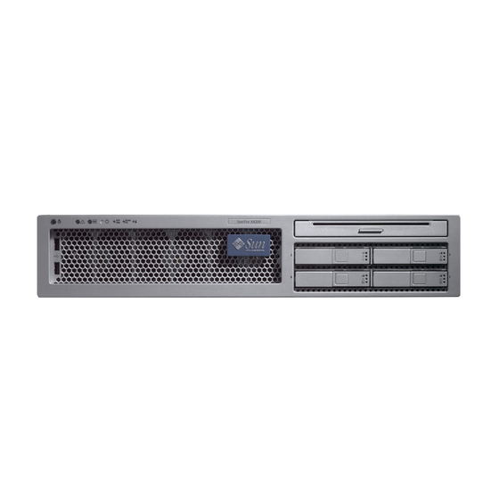
AC power cords from the back panel of the server. Power/OK LED Power button Serial number sticker on bezel Sun Fire X4100/X4100 M2 Server Front Panel FIGURE 1-2 Chapter 1 Initial Inspection of the Server... - Page 16 6. Verify that any after-factory components are qualified and supported. For a list of supported PCI cards and DIMMs, refer to the Sun Fire X4100/X4100 M2 and Sun Fire X4200/X4200 M2 Servers Service Manual, 819-1157. 7. Check that the installed DIMMs comply with the supported DIMM population rules and configurations, as described in “Troubleshooting DIMM Problems”...
- Page 17 9. To restore main power mode to the server (all components powered on), use a ballpoint pen or other pointed object to press and release the Power button on the server front panel. See FIGURE 1-2 FIGURE 1-3 When main power is applied to the full server, the Power/OK LED next to the Power button lights and remains lit.
-
Page 18: Troubleshooting Dimm Problems
| 02/16/2006 | 03:32:55 | System Firmware Progress | Motherboard initialization f600 | 02/16/2006 | 03:32:55 | System Firmware Progress | Video initialization f700 | 02/16/2006 | 03:33:01 | System Firmware Progress | USB resource configuration Sun Fire X4100/X4100 M2 and X4200/X4200 M2 Servers Diagnostics Guide • May 2007... -
Page 19: Correctable Dimm Errors
Correctable DIMM Errors At this time, correctable errors are not logged in the server’s system event logs. They are reported or handled in the supported operating systems as follows: Windows server: A Machine Check error message bubble pops up on task bar. ■... - Page 20 The following conditions will cause this error message: DIMMs Manufacturer not supported ■ Only Samsung, Micron, Infineon and SMART DIMMs are supported ■ This will be displayed when you add Hitachi DIMMs Sun Fire X4100/X4100 M2 and X4200/X4200 M2 Servers Diagnostics Guide • May 2007...
-
Page 21: Dimm Fault Leds
M2/X4200 M2 servers regarding the power requirements for viewing the DIMM fault LEDs: Sun Fire X4100/X4200 servers only: To see the DIMM fault LEDs, you must put ■ the server in standby power mode, with the AC power cords attached. See “Internally Inspecting the Server”... - Page 22 Pair 0 = DIMM 0 + DIMM 1 Pair 1 = DIMM 2 + DIMM 3 CPU1 CPU0 DIMM fault LEDs in DIMM ejector levers Sun Fire X4100/X4200 DIMM Slot Locations FIGURE 1-4 Sun Fire X4100/X4100 M2 and X4200/X4200 M2 Servers Diagnostics Guide • May 2007...
- Page 23 Pair 0 = DIMM B1 + DIMM A1 Pair 1 = DIMM B0 + DIMM A0 CPU1 CPU0 DIMM fault LEDs in DIMM ejector levers Sun Fire X4100 M2/X4200 M2 DIMM Slot Locations FIGURE 1-5 Chapter 1 Initial Inspection of the Server...
-
Page 24: Dimm Population Rules
DIMM Population Rules Note – The Sun Fire X4100/X4200 servers use only DDR1 DIMM. The Sun Fire X4100 M2/X4200 M2 servers use only DDR2 DIMMs. Sun Fire X4100/X4200 Rules The DIMM population rules for the Sun Fire X4100/X4200 servers are listed here: Each CPU can support a maximum of four DDR1 DIMMs. -
Page 25: Sun Fire X4100 M2/X4200 M2 Rules
4 GB 4 GB 16 GB Sun Fire X4100 M2/X4200 M2 Rules The DIMM population rules for the Sun Fire X4100 M2/X4200 M2 servers are listed here: Each CPU can support a maximum of four DDR2 DIMMs. ■ Each pair of DIMMs must be identical (same manufacturer, size, and speed). -
Page 26: Isolating And Correcting Dimm Ecc Errors
Sun Fire X4100/X4200 servers. The pair 0+1 is equivalent to pair A1+B1, and pair 2+3 is equivalent to pair A0+B0, in the Sun Fire X4100 M2/X4200 M2 servers. In this example, the log file reports an error with the DIMM in CPU0, slot 1. The fault LEDs on CPU0, slots 0+1 are lit. - Page 27 11. Power on the server and run the diagnostics test again. 12. Review the log file. If the error now appears in CPU0, slot 0 (opposite to the original error in slot 1), ■ the problem is related to the individual DIMM. In this case, return both DIMMs (the pair) to the Support Center for replacement.
- Page 28 Sun Fire X4100/X4100 M2 and X4200/X4200 M2 Servers Diagnostics Guide • May 2007...
-
Page 29: Diagnostic Testing Software
C H A P T E R Diagnostic Testing Software This chapter contains information about a diagnostic software tools that you can use. Note – This chapter applies to all Sun Fire X4100/X4100 M2 and X4200/X4200 M2 servers, unless otherwise noted. SunVTS Diagnostic Tests The servers are shipped with a Bootable Diagnostics CD (705-1439) that contains SunVTS™... -
Page 30: Sunvts Documentation
Requirements To use the Bootable Diagnostics CD, you must have a keyboard, mouse, and ■ monitor attached to the server on which you are performing diagnostics. Sun Fire X4100/X4100 M2 and X4200/X4200 M2 Servers Diagnostics Guide • May 2007... -
Page 31: Using The Bootable Diagnostics Cd
Using the Bootable Diagnostics CD To use the Bootable Diagnostics CD to perform diagnostics: 1. With the server powered on, insert the Bootable Diagnostics CD into the DVD- ROM drive. 2. Reboot the server, but press F2 during the start of reboot so that you can change the BIOS setting for boot-device priority. - Page 32 Diagnostics CD, the server boots from the CD. Therefore, the test log files are not on the server’s hard disk drive and they will be deleted when you power cycle the server. Sun Fire X4100/X4100 M2 and X4200/X4200 M2 Servers Diagnostics Guide • May 2007...
-
Page 33: Bios Event Logs And Post Codes
BIOS Event Logs and POST Codes This appendix contains information about BIOS event logs, power-on self test (POST), and console redirection. Note – This chapter applies to all Sun Fire X4100/X4100 M2 and X4200/X4200 M2 servers, unless otherwise noted. Viewing BIOS Event Logs Use this procedure to view the BIOS event log and the BMC system event log: 1. - Page 34 5. If the problem with the server is not evident, continue with “Using the ILOM SP GUI to View System Information” on page 43, or “Using IPMItool to View System Information” on page Sun Fire X4100/X4100 M2 and X4200/X4200 M2 Servers Diagnostics Guide • May 2007...
-
Page 35: Power-On Self-Test (Post)
Power-On Self-Test (POST) The system BIOS provides a rudimentary power-on self-test. The basic devices required for the server to operate are checked, memory is tested, the LSI 1064 disk controller and attached disks are probed and enumerated, and the two Intel dual- gigabit Ethernet controllers are initialized. -
Page 36: Redirecting Console Output
12. When you are prompted for a user name and password, type the following: User Name: root ■ Password: changeme ■ The current POST screen is displayed. Sun Fire X4100/X4100 M2 and X4200/X4200 M2 Servers Diagnostics Guide • May 2007... -
Page 37: Changing Post Options
Changing POST Options These instructions are optional, but you can use them to change the operations that the server performs during POST testing. 1. Initialize the BIOS Setup utility by pressing the F2 key while the system is performing the power-on self-test (POST). The BIOS Main menu screen is displayed. -
Page 38: Post Codes
Detecting the presence of Keyboard in KBC port. 000e Testing and initialization of different Input Devices. Traps the INT09h vector, so that the POST INT09h handler gets control for IRQ1. Sun Fire X4100/X4100 M2 and X4200/X4200 M2 Servers Diagnostics Guide • May 2007... - Page 39 POST Codes (Continued) TABLE A-1 Post Code Description 8600 Preparing CPU for booting to OS by copying all of the context of the BSP to all application processors present. NOTE: APs are left in the CLI HLT state. de00 Preparing CPU for booting to OS by copying all of the context of the BSP to all application processors present.
-
Page 40: Post Code Checkpoints
CPU frequency has been calculated to prevent bad programming. Initializes the 8042 compatible Keyboard Controller. Detects the presence of PS/2 mouse. Detects the presence of Keyboard in KBC port. Sun Fire X4100/X4100 M2 and X4200/X4200 M2 Servers Diagnostics Guide • May 2007... - Page 41 POST Code Checkpoints (Continued) TABLE A-2 Post Code Description Testing and initialization of different Input Devices. Also, update the Kernel Variables. Traps the INT09h vector, so that the POST INT09h handler gets control for IRQ1. Uncompress all available language, BIOS logo, and Silent logo modules. Initialize PM regs and PM PCI regs at Early-POST, Initialize multi host bridge, if system support it.
- Page 42 OS. Programmed the system BIOS (0F0000h shadow RAM) cacheability. Ported to handle any OEM specific programming needed during End-POST. Copy OEM specific data from POST_DSEG to RUN_CSEG. Sun Fire X4100/X4100 M2 and X4200/X4200 M2 Servers Diagnostics Guide • May 2007...
- Page 43 POST Code Checkpoints (Continued) TABLE A-2 Post Code Description Save system context for ACPI. Prepares CPU for booting to OS by copying all of the context of the BSP to all application processors present. NOTE: APs are left in the CLIHLT state. 61-70 OEM POST Error.
- Page 44 Sun Fire X4100/X4100 M2 and X4200/X4200 M2 Servers Diagnostics Guide • May 2007...
-
Page 45: Status Indicator Leds
A P P E N D I X Status Indicator LEDs This appendix describes the locations and definitions of the system LEDs. Note – This chapter applies to all Sun Fire X4100/X4100 M2 and X4200/X4200 M2 servers, unless otherwise noted. External Status Indicator LEDs show the locations of the external status indicator LEDs. - Page 46 GRASP board and the power supply fans. • On: Server is in main power mode with AC power supplied to all components. Sun Fire X4100/X4100 M2 and X4200/X4200 M2 Servers Diagnostics Guide • May 2007...
- Page 47 (Continued)Front Panel LED Functions TABLE B-1 LED Name Description Front Fan Fault LED This LED lights when there is a failed front cooling fan module. LEDs on the individual fan modules indicate which fan module has failed. Power Supply/Rear Fan Tray This LED lights when: Fault LED •...
- Page 48 GRASP board and the power supply fans. • On: Server is in main power mode with AC power supplied to all components. Sun Fire X4100/X4100 M2 and X4200/X4200 M2 Servers Diagnostics Guide • May 2007...
-
Page 49: Internal Status Indicator Leds
Sun Fire X4100/X4200 M2 servers regarding the power requirements for viewing the DIMM fault LEDs: For the original Sun Fire X4100/X4200 servers, to see the DIMM fault LEDs, you ■ must put the server in standby power mode, with the AC power cords attached. - Page 50 DIMM ejector levers CPU fault LEDs on the motherboard Fan module fault LEDs on fan modules Front panel of server Sun Fire X4100/X4200 Internal LED Locations FIGURE B-3 Sun Fire X4100/X4100 M2 and X4200/X4200 M2 Servers Diagnostics Guide • May 2007...
- Page 51 DIMM B1 DIMM B1 CPU1 CPU0 DIMM fault LEDs in DIMM ejector levers CPU fault LEDs on the motherboard Fan module fault LEDs on fan modules Sun Fire X4100 M2/X4200 M2 Internal LED Locations FIGURE B-4 Appendix B Status Indicator LEDs...
- Page 52 GRASP Board Power Status This LED has two states: • Off: standby power is not reaching the GRASP board. • Lit (green): 3.3V standby power is reaching the GRASP board. Sun Fire X4100/X4100 M2 and X4200/X4200 M2 Servers Diagnostics Guide • May 2007...
-
Page 53: Using The Ilom Sp Gui To View System Information
A P P E N D I X Using the ILOM SP GUI to View System Information Note – This chapter applies to all Sun Fire X4100/X4100 M2 and X4200/X4200 M2 servers, unless otherwise noted. This appendix contains information about using the Integrated Lights-Out Manager (ILOM) Service processor (SP) GUI to view monitoring and maintenance information for your server. -
Page 54: Making A Serial Connection To The Sp
“Viewing ILOM SP Event Logs” on page 45 ■ “Viewing Replaceable Component Information” on page 48 ■ “Viewing Temperature, Voltage, and Fan Sensor Readings” on page 50 ■ Sun Fire X4100/X4100 M2 and X4200/X4200 M2 Servers Diagnostics Guide • May 2007... -
Page 55: Viewing Ilom Sp Event Logs
Viewing ILOM SP Event Logs The IPMI system event log (SEL) provides status information about the server’s hardware and software to the ILOM software, which displays the events in the ILOM web GUI. Events are notifications that occur in response to some actions. 1. - Page 56 5. Click OK to clear all entries in the log. 6. If the problem with the server is not evident after viewing ILOM SP logs and information, continue with “SunVTS Diagnostic Tests” on page Sun Fire X4100/X4100 M2 and X4200/X4200 M2 Servers Diagnostics Guide • May 2007...
-
Page 57: Interpreting Event Log Time Stamps
Interpreting Event Log Time Stamps The system event log time stamps are related to the service processor clock settings. If the clock settings change, the change is reflected in the time stamps. When the service processor reboots, the SP clock is set to Thu Jan 1 00:00:00 UTC 1970. -
Page 58: Viewing Replaceable Component Information
The default user name and password are: Default user name: root Default password: changeme 2. From the System Information tab, choose Components. The Replaceable Component Information page is displayed. See FIGURE C-2 Sun Fire X4100/X4100 M2 and X4200/X4200 M2 Servers Diagnostics Guide • May 2007... - Page 59 Sample Replaceable Component Information Screen FIGURE C-2 3. Select a component from the drop-down list box. Information about the selected component is displayed. 4. If the problem with the server is not evident after viewing ILOM SP logs and information, continue with “SunVTS Diagnostic Tests”...
-
Page 60: Viewing Temperature, Voltage, And Fan Sensor Readings
The default user name and password are: Default user name: root Default password: changeme 2. From the System Monitoring tab, choose Sensor Readings. The Sensor Readings page is displayed. See FIGURE C-3 Sun Fire X4100/X4100 M2 and X4200/X4200 M2 Servers Diagnostics Guide • May 2007... - Page 61 Sample Sensor Readings Screen FIGURE C-3 3. Select the type of sensor readings that you want to view from the drop-down list box. You can select All Sensors, Temperature Sensors, Voltage Sensors, or Fan Sensors. Appendix C Using the ILOM SP GUI to View System Information...
- Page 62 Sensor thresholds include the following: Low/High NR: Low or high non-recoverable ■ Low/High CR: Low or high critical ■ Low/High NC: Low or high non-critical ■ Sun Fire X4100/X4100 M2 and X4200/X4200 M2 Servers Diagnostics Guide • May 2007...
-
Page 63: Sunvts Diagnostic Tests" On Page
Sample Sensor Readings Screen, With Thresholds Shown FIGURE C-4 6. Click the Hide Thresholds button to revert to the sensor readings. The sensor readings are redisplayed, without the thresholds. 7. If the problem with the server is not evident after viewing ILOM SP logs and information, continue with “SunVTS Diagnostic Tests”... - Page 64 Sun Fire X4100/X4100 M2 and X4200/X4200 M2 Servers Diagnostics Guide • May 2007...
-
Page 65: Using Ipmitool To View System Information
A P P E N D I X Using IPMItool to View System Information Note – This chapter applies to all Sun Fire X4100/X4100 M2 and X4200/X4200 M2 servers, unless otherwise noted. Caution – Although you can use IPMItool to view sensor and LED information, do not use any interface other than the ILOM CLI or Web GUI to alter the state or configuration of any sensor or LED. -
Page 66: About Ipmi
After you install the IPMItool package, you can access detailed information about command usage and syntax from the man page that is installed. From a command line, type this command: man ipmitool Sun Fire X4100/X4100 M2 and X4200/X4200 M2 Servers Diagnostics Guide • May 2007... -
Page 67: Connecting To The Server With Ipmitool
Connecting to the Server With IPMItool To connect over a remote interface you must supply a user name and password. The default user with admin-level access is with password . This means root changeme you must use the parameters to pass both user name and password on the command line, as shown in the following example: ipmitool -I lanplus -H <IPADDR>... -
Page 68: Changing The Default Password
You can also clear the key for a particular user, for example: ipmitool -I lanplus -H <IPADDR> -U root -P changeme sunoem sshkey del 2 Deleted SSH key for user id 2 Sun Fire X4100/X4100 M2 and X4200/X4200 M2 Servers Diagnostics Guide • May 2007... -
Page 69: Using Ipmitool To Read Sensors
Integrated Lights-Out Manager (ILOM) Administration Guide, 819-1160 and the Integrated Lights-Out Manager Supplement for Sun Fire X4100 and Sun Fire X4200 Servers, 819-5464. Reading Sensor Status There are a number of ways to read sensor status, from a broad overview that lists all sensors, to querying individual sensors and returning detailed information on them. -
Page 70: Reading Specific Sensors
| 36h | ok 3.1 | 2.64 Volts p1.v_+1v25core | 37h | ok 3.1 | 1.32 Volts ft0.fm0.f0.speed | 43h | ok | 29.0 | 6000 RPM Sun Fire X4100/X4100 M2 and X4200/X4200 M2 Servers Diagnostics Guide • May 2007... - Page 71 ft0.fm1.f0.speed | 44h | ok | 29.1 | 6000 RPM ft0.fm2.f0.speed | 45h | ok | 29.2 | 6000 RPM ft1.fm0.f0.speed | 46h | ok | 29.3 | 6000 RPM ft1.fm1.f0.speed | 47h | ok | 29.4 | 6000 RPM ft1.fm2.f0.speed | 48h | ok | 29.5 | 6000 RPM You can also generate a list of all sensors for a specific Entity.
-
Page 72: Using Ipmitool To View The Ilom Sp System Event Log
Repository (SDR). For increased speed, generate an SDR cache before using the . See “Using the Sensor Data Repository (SDR) Cache” on sel elist command page 64. For example: Sun Fire X4100/X4100 M2 and X4200/X4200 M2 Servers Diagnostics Guide • May 2007... -
Page 73: Clearing The Sel With Ipmitool
ipmitool -I lanplus -H <IPADDR> -U root -P changeme sel elist first 3 100 | Pre-Init Time-stamp | Temperature fp.t_amb | Upper Non-critical going high | Reading 31 > Threshold 30 degrees C 200 | Pre-Init Time-stamp | Power Supply ps1.pwrok | State Deasserted 300 | Pre-Init Time-stamp | Entity Presence ps1.prsnt | Device Present Certain qualifiers are available to refine and limit the SEL output. -
Page 74: Using The Sensor Data Repository (Sdr) Cache
For a detailed explanation of each sensor, listed by name, refer to the Integrated Lights Out Manager Supplement For Sun Fire X4100 and Sun Fire X4200 Servers, 819-5464. Sun Fire X4100/X4100 M2 and X4200/X4200 M2 Servers Diagnostics Guide • May 2007... -
Page 75: Viewing Component Information With Ipmitool
: HUNTSVILLE,AL,USA Board Extra : b302 Board Extra : 06 Board Extra : GRASP Product Manufacturer : SUN MICROSYSTEMS Product Name : ILOM FRU Device Description : sp.net0.fru (ID 2) Product Manufacturer : MOTOROLA Product Name : FAST ETHERNET CONTROLLER... -
Page 76: Viewing And Setting Status Leds
(this is because display an event every time it flashed in the blink cycle). lists the LED sensor IDs in these servers. See “Status Indicator LEDs” on TABLE D-2 page 35 for diagrams of the LED locations. Sun Fire X4100/X4100 M2 and X4200/X4200 M2 Servers Diagnostics Guide • May 2007... - Page 77 LED Sensor IDs TABLE D-2 LED Sensor ID Description sys.power.led System Power (front+back) sys.locate.led System Locate (front+back) sys.alert.led System Alert (front+back) sys.psfail.led System Power Supply Failed sys.tempfail.led System Over Temperature sys.fanfail.led System Fan Failed bp.power.led Back Panel Power bp.locate.led Back Panel Locate bp.alert.led Back Panel Alert fp.power.led...
-
Page 78: Led Modes
LEDS rather than a single physical LED. describes the LED sensor groups. TABLE D-4 Sun Fire X4100/X4100 M2 and X4200/X4200 M2 Servers Diagnostics Guide • May 2007... -
Page 79: Using Ipmitool Scripts For Testing
LED Sensor Groups TABLE D-4 Group Name Sensors in Group sys.power.led bp.power.led fp.power.led sys.locate.led bp.locate.led fp.locate.led sys.alert.led bp.alert.led fp.alert.led For example, to set both the front and back panel Power/OK leds to a standby blink rate, you could use this command: ipmitool -I lanplus -H <IPADDR>... - Page 80 Sun Fire X4100/X4100 M2 and X4200/X4200 M2 Servers Diagnostics Guide • May 2007...
-
Page 81: Error Handling
A P P E N D I X Error Handling Note – This chapter applies to all Sun Fire X4100/X4100 M2 and X4200/X4200 M2 servers, unless otherwise noted. This appendix contains information about how the servers process and log errors. - Page 82 The BIOS skips the faulty DIMM on the next POST memory test. ■ The BIOS reports available memory, excluding the faulty DIMM pair. ■ shows an example of a DMI log screen from BIOS Setup Page. FIGURE E-1 Sun Fire X4100/X4100 M2 and X4200/X4200 M2 Servers Diagnostics Guide • May 2007...
- Page 83 Sample DMI Log Screen, Uncorrectable Error FIGURE E-1 Appendix E Error Handling...
-
Page 84: Handling Of Correctable Errors
■ and Memory subsystems. shows an example of a DMI log screen from BIOS Setup Page: ■ FIGURE E-2 DMI Log Screen, Correctable Error Sample FIGURE E-2 Sun Fire X4100/X4100 M2 and X4200/X4200 M2 Servers Diagnostics Guide • May 2007... - Page 85 If during any stage of memory testing the BIOS finds itself incapable of ■ reading/writing to the DIMM, it takes the following actions: The BIOS disables the DIMM as indicated by the Memory Decreased message ■ in the example in FIGURE E-3 The BIOS logs an SEL record.
-
Page 86: Handling Of Parity Errors (Perr)
Event Data : 04ff00 Description : PCI PERR shows an example of a DMI log screen from BIOS Setup Page, with a ■ FIGURE E-4 parity error. Sun Fire X4100/X4100 M2 and X4200/X4200 M2 Servers Diagnostics Guide • May 2007... - Page 87 DMI Log Screen, PCI Parity Error Sample FIGURE E-4 The BIOS displays the following messages and freezes (during POST or DOS): ■ NMI EVENT!! ■ System Halted due to Fatal NMI! ■ The Linux NMI trap catches the interrupt and reports the following NMI ■...
- Page 88 Aug 5 05:15:00 d-mpk12-53-159 kernel: Do you have a strange power saving mode enabled? Note – The Linux system reboots, but does not inform the BIOS of this incident. Sun Fire X4100/X4100 M2 and X4200/X4200 M2 Servers Diagnostics Guide • May 2007...
-
Page 89: Handling Of System Errors (Serr)
Handling of System Errors (SERR) This section lists facts and considerations about how the server handles system errors (SERR). System error handling works through the HyperTransport Synch Flood Error ■ mechanism in the AMD controller. The following events happen during BIOS POST: ■... - Page 90 DMI log screen from the BIOS Setup Page with a ■ FIGURE E-6 system error. DMI Log Screen, System Error Listed Sample FIGURE E-6 Sun Fire X4100/X4100 M2 and X4200/X4200 M2 Servers Diagnostics Guide • May 2007...
-
Page 91: Handling Mismatching Processors
Microcode Revision, CPU0 : 0, CPU1 : 0 DRAM Clocking CPU0 = 400 MHz, CPU1 Core0/1 = 400 MHz Sun Fire X4100 Server, 1 AMD North Bridge, Rev E4 1 AMD North Bridge, Rev E6 1 AMD 8111 I/O Hub, Rev C2... -
Page 92: Hardware Error Handling Summary
BSP fails to operate correctly) BIOS just halts without logging. For some other POST failures subsequent to memory and SP initialization, the BIOS logs a message to the SP’s SEL. Sun Fire X4100/X4100 M2 and X4200/X4200 M2 Servers Diagnostics Guide • May 2007... - Page 93 Hardware Error Handling Summary TABLE E-1 Logged (DMI Log or SP Error Description Handling SEL) Fatal? Single-bit With ECC enabled The CPU corrects the error in hardware. No SP SEL Normal DRAM ECC in the BIOS Setup, interrupt or machine check is generated by operation error the CPU detects...
- Page 94 Fan failure is de- The Front Fan Fault, Service Action Re- SP SEL Non-fatal tected by reading quired, and individual fan module LEDs are tach signals. lit. Sun Fire X4100/X4100 M2 and X4200/X4200 M2 Servers Diagnostics Guide • May 2007...
- Page 95 Hardware Error Handling Summary TABLE E-1 Logged (DMI Log or SP Error Description Handling SEL) Fatal? Multiple fan Fan failure is de- The Front Fan Fault, Service Action Re- SP SEL Fatal failure tected by reading quired, and individual fan module LEDs are tach signals.
- Page 96 Sun Fire X4100/X4100 M2 and X4200/X4200 M2 Servers Diagnostics Guide • May 2007...
- Page 97 Index isolating errors 16 population rules 14 anonymous user, IPMItool 57 emergency shutdown 5 back panel LEDs error handling definitions 38 correctable 74 locations 37 hardware errors 82 BIOS mismatching processors 81 event logs 23 parity errors 76 POST code checkpoints 30 system errors 79 POST codes 28 uncorrectable errors 71...
- Page 98 65 changing options 27 viewing LED status 66 code checkpoints 30 viewing sensor status 59 codes table 28 viewing SP SEL 62 overview 25 Sun Fire X4100/X4100 M2 and X4200/X4200 M2 Servers Diagnostics Guide • May 2007...
- Page 99 redirecting console output 26 system errors, handling 79 Power button, front panel 5 System Overheat Fault LED 37 power off procedure 5 power supply status LEDs 38 time stamps in ILOM SP SEL 47 Power Supply/Rear Fan Tray Fault LED 37 troubleshooting guidelines 3 Power/OK LED 36 power-on self test, see POST...
- Page 100 Sun Fire X4100/X4100 M2 and X4200/X4200 M2 Servers Diagnostics Guide • May 2007...
Need help?
Do you have a question about the Fire X4100 and is the answer not in the manual?
Questions and answers