La Cornue AlberTine 36 User Manual & Installation & Service Instructions
Dual fuel range
Hide thumbs
Also See for AlberTine 36:
- User manual (52 pages) ,
- Conversion manual (13 pages) ,
- User manual (48 pages)

Related Manuals for La Cornue AlberTine 36


Summary of Contents for La Cornue AlberTine 36
-
Page 1: User Guide
AlberTine 36 Dual Fuel Range AlberTine AlberTine User Guide & Installation & Service Instructions U109956 - 05A... -
Page 2: Table Of Contents
Contents Important Safety Information Range Overview Multi-function Oven cooking guide Cleaning Your Range Troubleshooting Installation Conversion to LP Gas Service and Parts Circuit Diagram 10. Technical Data 11. Warranty... -
Page 3: Important Safety Information
1. Important Safety Information Have your appliance properly installed and grounded by they may burn, melt or soften if left too close to a vent or a a qualified technician in accordance with the National lighted burner. Electrical Code ANSI/NFPA No. 70 – latest edition, and Storage should not be installed directly above a range. -
Page 4: Proper Installation
To avoid risk of electrical shock, personal injury, or death, primarily to the incomplete combustion of natural gas or make sure your range has been properly grounded and liquid petroleum (LP) fuels. Properly adjusted burners will always disconnect it from main power supply before minimize incomplete combustion. -
Page 5: Use The Right Size Pan
Use the Right Size Pan Placement of Oven Racks Always place oven racks in desired location while This appliance is equipped with burners of different sizes. Use utensils with flat bottoms. Do not use unstable pans and oven is cool. If rack must be moved while oven is hot, do not let potholder contact hot heating element in position the handles away from the edge of the cooktop. - Page 6 Always keep combustible wall coverings or curtains etc. a safe distance away from your range. Do not spray aerosols in the vicinity of the range while it is in use. Do not store or use combustible materials, or flammable liquids in the vicinity of this appliance.
-
Page 7: Range Overview
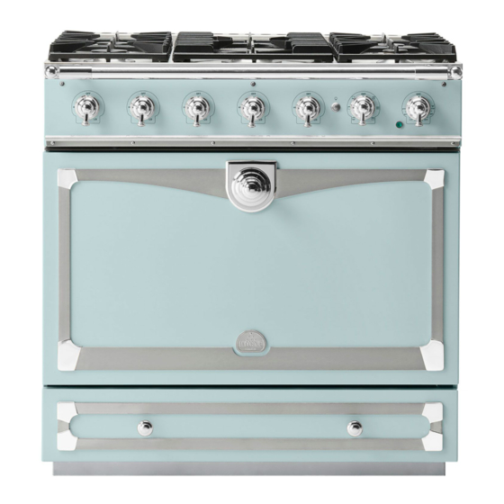
Range Overview The dual fuel single cavity range cooker has the following Fig.2-1 features: 5 hotplate burners including a wok burner A control panel A multi-function oven A storage drawer Cooktop Burners Note: Before using the cooktop make sure all burners are in place and all the grates on the range are properly placed. - Page 8 Igniting Cooktop Burners without Electricity Fig.2-9 Broiling elements If there is a power failure the cooktop burners can be lit with a match. Hold a burning match ½” from the burner head, keeping your hand as far horizontally away from the burner as possible.
- Page 9 Operating the Oven Fig.2-10 The multi-function oven has two controls: a function selector and a temperature setting knob (Fig.2-10). Turn the function selector control to a cooking function. Fig.2-11 shows the control set for conventional oven cooking. Turn the oven temperature knob to the temperature you need.
- Page 10 Rack levels 5 and 6 should be used depending on the size of Fig.2-14 the food being cooked. Convection Assisted Oven This function operates the fans, circulating air heated by the elements at the top and the base of the oven. The combination of fan and conventional ArtNo.030-0014 - Top &...
-
Page 11: Oven Racks
General Oven Tips Fig.2-15 IMPORTANT: Before using for the first time, to dispel manufacturing odors turn the ovens to 395°F (200°C) in Convection Assisted mode and run for one hour. To clear the smell, make sure the room is well ventilated to the outside air, by opening windows for example. -
Page 12: Oven Light
ArtNo.280-0055 - Removing Shelf Detail To remove and refit the racks Fig.2-20 The rack has a small kink on either side (Fig.2-20). To remove the rack, line these up with the stops in the rack support (Fig.2-21). Lift the rack upwards so that it will pass over the rack stop and then pull it forwards (Fig.2-22). - Page 13 Storage Fig.2-26 The bottom drawer is for storing oven trays and other cooking utensils. It can get very warm, don’t store anything in it, which may melt or catch fire. Never store flammable materials in the drawer. This includes paper, plastic and cloth items, such as ArtNo.341-0001 - 90SC - Drawer pulled forward cookbooks, plastic ware and towels, as well as flammable liquids.
-
Page 14: Multi-Function Oven Cooking Guide
3. Multi-function Oven cooking guide Remember – not all modes will be suitable for all food types. Fig.3-1 The oven control settings and cooking times given are intended to be used only as a guide. Individual tastes may require the temperature to be altered to provide a preferred result. - Page 15 Thoroughly thaw frozen meats and poultry before cooking. To cook on three levels, use racks 1, 3 and 5. ArtNo.030-0015 - Top & Bottom Symbol ArtN.050-0013 - Gas & electric cooking table USA ArtNo.030-0016 - MF Fan Oven Symbol Convection Conventional Oven Shelf Temperature °F...
-
Page 16: Cleaning Your Range
4. Cleaning Your Range Essential Information Recommended Part Finish Before thorough cleaning, turn off the circuit breaker. Allow cleaning method the range to cool. Burner grates & Porcelain enamel Mildly abrasive cleaner such as top of burner Bon Ami ® or Soft Scrub®. After cleaning remember to switch on the circuit breaker heads Dishwasher. -
Page 17: Control Panel And Oven Doors
Never use caustic or abrasive cleaners as these will Fig.4-1 damage the surface. Control Panel and Oven Doors Avoid using any abrasive cleaners including cream cleaners, on brushed stainless steel surfaces. For best results use liquid detergents. ArtNo.311-0030 - Burner head fitting The control panel and control knobs should only be cleaned with a soft cloth wrung out in clean hot soapy water –... -
Page 18: Troubleshooting
5. Troubleshooting Cooktop ignition or cooktop burners faulty service if they are correcting work carried out by your Is the power on? original installer. It is in your interest to track down your original installer. Are the sparker (ignition electrode) or burner holes blocked by debris? Current Operated Ground Fault Circuit Breaker Are the burner heads correctly located? See the section... - Page 19 Make sure the oven is cool. Open the oven door and Fig.5-1 remove the oven racks. Unscrew the bulb cover by turning counter clockwise. It may be very stiff (Fig.5-2). ArtNo.324-0005 Oven light bulb Taking care to protect your fingers in case the bulb should shatter, unscrew the old bulb.
- Page 20 WARNING! If the information in this manual is not followed exactly, a fire or explosion may result causing property damage, personal injury or death. Do not store or use gasoline or other flammable vapors and liquids in the vicinity of this or any other appliance. WHAT TO DO IF YOU SMELL GAS Do not try to light any appliance.
-
Page 21: Installation
INSTALLATION Check the appliance is electrically safe and gas sound when you have finished. 6. Installation Regulations Installation Safety Instructions Installation of this range must conform with local codes, or in Improper installation, adjustment, alteration, service or maintenance can cause injury or property the absence of local codes, with the National Fuel Gas Code, damage. - Page 22 INSTALLATION Check the appliance is electrically safe and gas sound when you have finished. Location of the Range Checking the parts: Do not locate the range where it may be subject to strong 6 grates Leveling tool and Allen key drafts.
-
Page 23: Positioning The Range
INSTALLATION Check the appliance is electrically safe and gas sound when you have finished. Positioning the Range Fig.6-1 Fig.6-1 and Fig.6-2 show the minimum recommended distances and clearances from the range to nearby surfaces. Min 35½” (90cm) - 36“ (91cm) For Canada, min 363/8”... -
Page 24: Removing The Door
ArtNo.281-0017 - Removing the door INSTALLATION Check the appliance is electrically safe and gas sound when you have finished. Moving the Range Fig.6-4 The range is very heavy. Take great care. We recommend two people maneuver the range. Ensure that the floor covering is firmly attached, or removed to prevent it being disturbed when moving the range around. - Page 25 INSTALLATION Check the appliance is electrically safe and gas sound when you have finished. Installing the Flue Grille Fig.6-8 The flue grille is packed separately (Fig.6-9). ArtNo.010-0009 Pushing the cooker The larger of the holes along the sides are for screwdriver access and should face to the rear.
- Page 26 INSTALLATION Check the appliance is electrically safe and gas sound when you have finished. Wall Attachment Fig.6-15 When floor attachment is impractical you may attach the anti-tip bracket base securely to a solid wall or wall stud (Fig.6-15). For both floor and wall attachment it is essential to use the appropriate fixing screws and to ensure that the Anti-Tip bracket is firmly attached.
-
Page 27: Electrical Requirements
INSTALLATION Check the appliance is electrically safe and gas sound when you have finished. Electrical Connection Fig.6-19 When installed the range must be electrically grounded in accordance with local codes or; in the absence of local codes with the National Electrical Code ANSI/NFPA 70, latest edition. 16”... - Page 28 INSTALLATION Check the appliance is electrically safe and gas sound when you have finished. 4-Wire Conduit Installation Fig.6-21 Disconnect the supplied power cord from the terminal block and ground post. Keep the terminal block parts; you will need them. Remove the strain relief clamp from the power cord and remove the power cord and strain relief clamp from the mounting bracket (Fig.6-21).
- Page 29 INSTALLATION Check the appliance is electrically safe and gas sound when you have finished. 3-Wire Conduit Installation Fig.6-27 Disconnect the supplied power cord from the terminal block and ground post. Keep the terminal block parts; you will need them. Remove the strain relief clamp from the power cord ArtNo.280-0039 Reducer Plate and remove the power cord and strain relief clamp from the mounting bracket.
-
Page 30: Gas Connection
INSTALLATION Check the appliance is electrically safe and gas sound when you have finished. Gas Connection Fig.6-30 Installation of this range must conform with local codes or, in the absence of local codes, with the National Fuel Gas Code, ANSI Z223.1-latest edition. 16”... - Page 31 INSTALLATION Check the appliance is electrically safe and gas sound when you have finished. Connect the Range to the Gas Supply Fig.6-33 Shut off the main gas supply valve before disconnecting the Appliance old range and leave it off until the new hookup has been Flexible connector Adaptor gas inlet...
- Page 32 INSTALLATION Check the appliance is electrically safe and gas sound when you have finished. Seal the Openings Fig.6-34 Seal any openings in the wall behind the range and in the floor under the range when hookups are completed. IMPORTANT: When all connections are completed make ArtNo.280-0044 Cornufe Knobs 5 sure the flow of combustion and ventilation air to the range is unobstructed.
- Page 33 INSTALLATION Check the appliance is electrically safe and gas sound when you have finished. Installing the Toe Kick Fig.6-42 Remove the 3 screws for the toe kick mounts along the front bottom edge of the range. Fasten the toe kick using these screws (alternative color screws can be found in the loose parts pack).
-
Page 34: Range Operational Checks
INSTALLATION Check the appliance is electrically safe and gas sound when you have finished. Range operational checks How To Move the Range for Servicing Follow these procedures to remove appliance for servicing: Oven Check • Shut off the gas supply and turn off the circuit breaker. Turn on the oven and check that the oven fans start to turn and that the oven starts to heat up. - Page 35 WARNING! If the information in this manual is not followed exactly, a fire or explosion may result causing property damage, personal injury or death. Do not store or use gasoline or other flammable vapors and liquids in the vicinity of this or any other appliance. WHAT TO DO IF YOU SMELL GAS Do not try to light any appliance.
-
Page 36: Conversion To Lp Gas
INSTALLATION Check the appliance is electrically safe and gas sound when you have finished. 7. Conversion to LP Gas Important Fig.7-1 • Observe all governing codes and ordinances. Burner head • The range must be properly grounded. • Save these instructions for the local electrical inspector’s use. Brass venturi Burner base When servicing or replacing gas carrying components disconnect from gas before commencing operation and check appliance is gas sound after completion. -
Page 37: Valve Adjustment
INSTALLATION Check the appliance is electrically safe and gas sound when you have finished. Replace the rings on the burners. Screw in the hexagon Fig.7-2 Fig.7-3 headed venturi to make fitting the burners easier. Do not tighten yet. ArtNo.0102-0001 - Unscrewing When all the burner bases and venturis have been fitted the control valve bypass screw tighten the venturi nuts. -
Page 38: Stick On Label
INSTALLATION Check the appliance is electrically safe and gas sound when you have finished. Type 1 Fig.7-7 Unscrew the hexagonal nut in the front of the regulator. The regulator nut has a plastic snap-in converter device on the underside (Fig.7-7). To convert the regulator snap the device ArtNo.103-0006 - Maxitrol cap &... - Page 39 INSTALLATION Check the appliance is electrically safe and gas sound when you have finished. Replace the storage drawer Fig.7-12 To replace the drawer in the range, pull the side rails fully out (Fig.7-13). At each side, hold the front of the drawer and pull the side rail forward so that the clips click into position, holding the drawer to the side rails.
-
Page 40: Service And Parts
’Troubleshooting’ section, first to check that you are using the appliance correctly. If you are still having difficulty, contact: Retailers Name & Address La Cornue Service Center Phone: 877-LACORNUE (7:00 am - 4:00 pm M-F Pacific time). Please note If your appliance is outside the 3 year warranty period our service provider may charge for this visit. -
Page 41: Circuit Diagram
9. Circuit Diagram ArtNo.080-0061 - 90SC DF - LaCornue 36 circuit diagram [USA] r (f) Clear boots r (f) clear clear clear r (f) r (f) Black boots Code Description Code Description Color Code Function controller Left-hand fan element Blue Temperature controller Left-hand fan Brown... -
Page 42: Technical Data
10. Technical Data INSTALLER: Please leave these instructions with the user. DATA BADGE LOCATION: Inside base drawer of cavity. Remove the drawer (see Overview > Storage for details). COUNTRY OF DESTINATION: USA/Canada Connections ArtNo280-0090 Drawer Cavity & Badges Electric 240 V 60 Hz ½”... -
Page 43: Warranty
All repair labor and replacement parts found to be defective The warranty applies even if you should move. due to materials and workmanship. LA CORNUE DOES NOT ASSUME ANY RESPONSIBILITY FOR Any damage due to transit must be reported within 15 days INCIDENTAL OR CONSEQUENTIAL DAMAGES. - Page 44 ArtNo280-0093 Back Cover Bar...
Need help?
Do you have a question about the AlberTine 36 and is the answer not in the manual?
Questions and answers