
Related Manuals for La Cornue AlberTine 36 C9GP


Summary of Contents for La Cornue AlberTine 36 C9GP
- Page 1 AlberTine 36 Dual Fuel Range AlberTine User Guide & Installation & Service Instructions U109956 - 17...
- Page 3 WARNING! If the information in these instructions is not followed exactly, a fire or explosion may result, causing property damage, personal injury or death. DO NOT store or use gasoline or other flammable vapors and liquids in the vicinity of this or any other appliance. WHAT TO DO IF YOU SMELL GAS DO NOT try to light any appliance.
- Page 4 The following symbols are related to safety and are used on the product and throughout this manual. Meaning / Description Symbol Meaning / Description Symbol HEAVY WARNING / CAUTION This product is heavy and reference An appropriate safety instruction should be made to the safety should be followed or caution taken if instructions for provisions of lifting a potential hazard exists.
-
Page 5: Table Of Contents
Contents Important safety information Installation safety instructions 21 Range overview Installation Cooktop burners Accessories Cleaning Positioning the range The multifunction oven Moving the range Operating the oven Removing the door Steam Lowering the two rear rollers General oven tips Installing the flue grille Accessories Leveling Storage... -
Page 7: Important Safety Information
Important safety information Read all instructions before using this appliance. Save these If the range is installed near a window, proper precautions instructions for future reference. should be taken to prevent curtains from blowing over the burners. Have your appliance properly installed and grounded by NEVER leave any items on the range cooktop. - Page 8 Teach them not to play with controls or any other part of the They might catch fire if they touch a hot surface. range. Use dry oven gloves when applicable – using damp gloves NEVER store items of interest to children in the cabinets might result in steam burns when you touch a hot surface.
- Page 9 Cooktop burners Ovens Use care when opening the door. Quality of flames Let hot air and steam escape before removing or On Natural Gas, the burners’ flames should be a blueish color replacing food. with, at most, a slightly yellowish fringe. NEVER heat unopened food containers.
- Page 10 Take care when touching the range in order to Foods for frying should be as dry as possible. Frost on frozen minimize the possibility of burns; always be certain foods or moisture on fresh foods can cause hot fat to bubble that the controls are in the OFF position and that it is up and over the sides of the pan.
-
Page 11: Range Overview
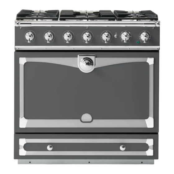
Range overview The dual fuel single cavity range cooker has the following Fig. 2.1 features: 5 hotplate burners Control panel Multifunction oven Storage drawer Cooktop burners Note: Before using the cooktop make sure all burners are in place and all the grates on the range are properly placed. The drawing by each knob indicates which burner that knob controls (Fig. -
Page 12: Cleaning
Igniting cooktop burners without electricity Top heat elements Fig. 2.9 If there is a power failure the cooktop burners can be lit with Broiling elements a match. Hold a burning match ½” from the burner head, keeping your hand as far horizontally away from the burner as possible. -
Page 13: Operating The Oven
Operating the oven Fig. 2.10 The multifunction oven has two controls: a function selector and a temperature setting knob (Fig. 2.10). Turn the function selector control to a cooking function. Fig. 2.11 shows the control set for conventional oven cooking. Turn the oven temperature knob to the temperature you need. - Page 14 Rack levels 5 and 6 should be used depending on the size of Fig. 2.14 the food being cooked. For best results we recommend that the grill pan is not located on the uppermost shelf. Convection assisted oven This function operates the fans, circulating air heated by the elements at the top and the base of the oven.
-
Page 15: Steam
Steam When cooking foods with high water content (e.g. oven fries) there may be some steam visible at the grille at the rear of the cooktop. This is perfectly normal. General oven tips IMPORTANT: Before using for the first time, to dispel manufacturing odors turn the ovens to 200 °C (395 °F) in Convection Assisted mode and run for one hour. -
Page 16: Accessories
Accessories Fig. 2.15 Please refer to “Accessories” page 24 Oven racks The oven racks are retained when pulled forward but can be easily removed and refitted. To fit the telescopic shelf runners With the runner arm in the closed position locate the opening of the upper rear slot onto the side support (Fig. -
Page 17: Storage
Oven light Fig. 2.18 Press the appropriate button to turn on the oven lights (Fig. 2.18). F° If one of the oven lights fail, turn off the range circuit breaker 450° 400° before you change the bulb. See the ‘Troubleshooting’ section 250°... -
Page 18: Oven Cooking Guide
Oven cooking guide Remember – not all modes will be suitable for all food Fig. 3.1 types. The oven control settings and cooking times given are intended to be used only as a guide only. Individual tastes may require the temperature to be altered to provide a preferred result. - Page 19 Cooking chart ArtNo.030-0015 - Top & Bottom Symbol ArtNo.030-0016 - MF Fan Oven Symbol Conventional Convection Rack oven oven position for conventional Temperature Temperature Approximate cooking time cooking °F °F Meat Beef (no bone) 30-35 minutes per 1 lb + 30-35 minutes 20-25 minutes per 1 lb + 20-25 minutes Lamb 30-35 minutes per 1 lb + 30-35 minutes...
-
Page 20: Cleaning Your Range
Cleaning your range Essential information Recommended Part Finish cleaning method Before thorough cleaning, turn off the circuit breaker. Allow the range to cool. Burner grates & Porcelain enamel Mildly abrasive cleaner such as top of burner Bon Ami ® or Soft Scrub®. After cleaning remember to switch on the circuit breaker heads Dishwasher. -
Page 21: Control Panel And Oven Doors
Never use caustic or abrasive cleaners as these will Fig. 4.1 damage the surface. Control panel and oven doors Avoid using any abrasive cleaners including cream cleaners, on brushed stainless steel surfaces. For best results use liquid detergents. ArtNo.311-0030 - Burner head fitting The control panel and control knobs should only be cleaned with a soft cloth wrung out in clean hot soapy water –... -
Page 22: Troubleshooting
Troubleshooting Cooktop ignition or cooktop burners faulty If there is an installation problem and I don’t get my original installer to come back to fix it who pays? Is the power on? You do. Service organizations will charge for their service if Are the sparker (ignition electrode) or burner holes blocked they are correcting work carried out by your original installer. - Page 23 The timed oven is not coming on when automatic 15 W - 110 V / 130 V Fig. 5.1 cooking Has the oven knob been left in the OFF position by mistake? Oven temperature getting hotter as the range gets older If turning the knob down has not worked or only worked for a short time then you may need a new thermostat.
-
Page 24: Installation Instructions
6. Installation Instructions WARNING! If the information in these instructions is not followed exactly, a fire or explosion may result, causing property damage, personal injury or death. DO NOT store or use gasoline or other flammable vapors and liquids in the vicinity of this or any other appliance. - Page 25 The following symbols are related to safety and are used on the product and throughout this manual. Meaning / Description Symbol Meaning / Description Symbol HEAVY WARNING / CAUTION This product is heavy and reference An appropriate safety instruction should be made to the safety should be followed or caution taken if instructions for provisions of lifting a potential hazard exists.
-
Page 26: Service And Parts
INSTALLATION Check the appliance is electrically safe when you have finished. Service and parts Firstly, please complete the appliance details below and keep them safe for future reference – this information will enable us to accurately identify the particular appliance and help us to help you. Filling this in now will save time and inconvenience if you later have a problem with the appliance. -
Page 27: Installation Safety Instructions
INSTALLATION Check the appliance is electrically safe when you have finished. Installation safety instructions Regulations Improper installation, adjustment, alteration, service or maintenance can cause injury or property Installation of this range must conform with local damage. Refer to this manual. For assistance or codes, or in the absence of local codes, with the additional information, consult a qualified engineer. - Page 28 INSTALLATION Check the appliance is electrically safe when you have finished. Converting to propane gas This appliance is supplied set for natural gas. A conversion kit for Propane gas is supplied with the range (A060048). The conversion must be performed by a qualified LP gas installer.
-
Page 29: Installation
INSTALLATION Check the appliance is electrically safe and gas sound when you have finished. Installation You will also need the following tools and equipment to complete the range installation satisfactorily. Multimeter Electric drill Masonry drill bit & anchors (only required if installing the range on a stone or concrete floor) Steel tape measure Phillips head screwdriver... -
Page 30: Accessories
INSTALLATION Check the appliance is electrically safe and gas sound when you have finished. Checking the parts: Toe kick Allen key 2.5 mm Rear Flue Grille page 27 Side extension kit page 28 page 36 ArtNo.350-0007 - Plinth USA ArtNo.351-0001 - Side extension panel USA Conversion kit from natural gas to Hand rail and end pieces... -
Page 31: Positioning The Range
INSTALLATION Check the appliance is electrically safe and gas sound when you have finished. Positioning the range Fig. 9.1 Fig. 9.1 and Fig. 9.2 show the minimum recommended distances and clearances from the range to nearby surfaces. Min 35½” (900 mm) - 36“ (910 mm) Min 35½”... -
Page 32: Moving The Range
INSTALLATION Check the appliance is electrically safe and gas sound when you have finished. Moving the range Fig. 9.4 On no account try and move the range while it is plugged into the electricity supply. This appliance is heavy. Ensure you have the correct facilities to complete the move. -
Page 33: Installing The Flue Grille
INSTALLATION Check the appliance is electrically safe and gas sound when you have finished. Installing the flue grille Fig. 9.9 The flue grille is packed separately (Fig. 9.9). ArtNo.280-0029 - Flue Grill The larger of the holes along the sides are for screwdriver access and should face to the rear. -
Page 34: Side Panel Extension Kit
INSTALLATION Check the appliance is electrically safe and gas sound when you have finished. Side panel extension kit Fig. 9.14 Outer anti- Outer stability Outer anti-tip bracket bracket Two side extension panels are supplied with the range. These bracket can be installed where the side of the range is exposed. The extension installation must be performed by a qualified gas Range Range... -
Page 35: Gas Connection
INSTALLATION Check the appliance is electrically safe and gas sound when you have finished. 10. Gas connection Installation of this range must conform with local codes or, in Gas supply Electrical Fig. 10.1 the absence of local codes, with the National Fuel Gas Code, zone supply zone ANSI Z223.1-latest edition. - Page 36 INSTALLATION Check the appliance is electrically safe and gas sound when you have finished. Connect the range to the gas supply Fig. 10.4 Shut off the main gas supply valve before disconnecting the Appliance Adaptor Flexible connector gas inlet old range and leave it off until the new hookup has been completed.
-
Page 37: Electrical Connection
INSTALLATION Check the appliance is electrically safe when you have finished. 11. Electrical connection Have your appliance properly installed and grounded by a qualified technician. The installation must conform with local codes, or in the absence of local codes, in accordance with the National Fuel Gas Code, ANSI Z223.1/NFPA 54 or, in Canada, the Natural Gas and Propane Installation Code, CSA B149.1 and in addition the National Electrical Code NFPA 70... - Page 38 INSTALLATION Check the appliance is electrically safe when you have finished. Recommended electrical outlet location Fig. 11.1 When connecting using a NEMA 14-50R receptacle, if possible position it so it can be accessed through the opening at the 8 ⁄ ” (225mm) Area accessible through drawer rear of the drawer cavity (Fig.
- Page 39 INSTALLATION Check the appliance is electrically safe when you have finished. Fitting a 3-Wire Power Cord Fig. 11.5 Disconnect the supplied power cord from the terminal block and ground post. Keep the terminal block parts; you will need them. Slacken the strain relief clamp from the power cord, untighten the 2 screws (Fig.
- Page 40 INSTALLATION Check the appliance is electrically safe when you have finished. 3-Wire Conduit Installation Fig. 11.7 Disconnect the supplied power cord from the terminal block and ground post. Keep the terminal block parts; you will need them. Remove the strain relief clamp from the power cord and remove the power cord and strain relief clamp from the mounting bracket.
- Page 41 INSTALLATION Check the appliance is electrically safe when you have finished. 4-Wire Conduit Installation Fig. 11.11 Disconnect the supplied power cord from the terminal block and ground post. Keep the terminal block parts; you will need them. Remove the strain relief clamp from the power cord and remove the power cord and strain relief clamp from the mounting bracket (Fig.
-
Page 42: Final Fitting And Checks
INSTALLATION Check the appliance is electrically safe and gas sound when you have finished. 12. Final fitting and checks Assemble the range Fig. 12.1 Fig. 12.2 Installing the control knobs The range is supplied with 5 burner control knobs. These are for the gas controls to the left of the control panel (Fig. -
Page 43: Range Operational Checks
INSTALLATION Check the appliance is electrically safe and gas sound when you have finished. Range operational checks How to move the range for servicing Oven check Follow these procedures to remove appliance for servicing: Turn on the oven and check that the oven fans start to turn and that the oven starts to heat up. -
Page 44: Fitting The Drawer
INSTALLATION Check the appliance is electrically safe when you have finished. Fitting the drawer Removing the drawer... -
Page 45: Circuit Diagram
13. Circuit diagram r (flag) Clear boots r (f) clear r (flag) r (flag) Black boots Code Description Code Description Left Hand Oven Multifunction Switch Ignition Switches Left Hand Oven Base Element Ignition Switch Left Hand Oven Fan Element Spark Generator Left hand Oven Top Outer Element Oven Light Code Color... -
Page 46: Technical Data
14. Technical data INSTALLER: Please leave these instructions with the user. DATA BADGE LOCATION: Inside base drawer of cavity. COUNTRY OF DESTINATION: USA/Canada Connections Electric 240 V 60 Hz ArtNo280-0090 Drawer Cavity & Badges ½” NPT at rear left-hand side Dimensions Model Albertine 90 Dual Fuel Overall height... -
Page 47: Warranty
The warranty applies even if you should move. LA CORNUE DOES NOT ASSUME ANY RESPONSIBILITY FOR INCIDENTAL OR CONSEQUENTIAL DAMAGES. Some states do not allow the exclusion or limitation of incidental or consequential damages, so the above limitation or exclusion may not apply to you. - Page 48 USA & CANADA Middleby Residential 4960 Golden Parkway, Buford, GA 30518 770-932-7282 www.lacornueusa.com AGA CONSUMER PRODUCTS...
Need help?
Do you have a question about the AlberTine 36 C9GP and is the answer not in the manual?
Questions and answers