La Cornue CornuFe 44 User Manual
Induction range
Hide thumbs
Also See for CornuFe 44:
- User's manual & installation instructions (56 pages) ,
- Conversion manual (13 pages) ,
- Quick start manual (12 pages)
Table of Contents
Advertisement
Quick Links
This book contains many important safety messages.
Always read and obey all safety messages.
Installer: Leave these instructions with the appliance
Important: Save the installation instructions for the local electrical inspector's use.
w w w . l a c o r n u e . c o m
CornuFé 44 Induction Range
User Guide
&
Installation Instructions
U111136 - 02
Advertisement
Table of Contents

Subscribe to Our Youtube Channel
Related Manuals for La Cornue CornuFe 44


Summary of Contents for La Cornue CornuFe 44
- Page 1 This book contains many important safety messages. Always read and obey all safety messages. Installer: Leave these instructions with the appliance Important: Save the installation instructions for the local electrical inspector’s use. w w w . l a c o r n u e . c o m CornuFé...
- Page 2 WARNING! The anti-tip device supplied with this range must be installed when the appliance is installed. This will reduce risk of tipping of the appliance from abnormal usage or by excessive loading of the oven door. WARNING! • ALL RANGES CAN TIP. •...
-
Page 3: Table Of Contents
Contents Installation safety instructions 24 Important safety information Range Overview 10. Installation Cooktop Positioning the Range Cooktop control indications & warnings Moving the Range The ovens Fitting the Flue Grille Accessories Lowering the Two Rear Rollers Oven Lights Completing the Move Storage Levelling the Range Telescopic runners... -
Page 4: Important Safety Information
Important safety information To prevent fire or smoke damage Have your appliance properly installed and grounded by a qualified technician. The installation must conform with local Before using the range make sure all the packing materials codes or, in the absence of local codes, in accordance with have been removed. - Page 5 DO NOT allow children to climb or play around the range. Wear suitable clothing The weight of a child on an open door may cause the range NEVER wear loose-fitting or hanging clothes while using the to tip, resulting in serious burns or other injury. Teach them range.
- Page 6 To fully utilize the power of your induction stove top and to ensure longevity of performance, we recommend the use of La Cornue approved Induction Pots and Pans. If you decide to purchase an alternative set of pans for use on Fig.
- Page 7 Use the right size pan General safety instructions This appliance is provided with rollers to facilitate This appliance is equipped with cooktop zones of different sizes. Use utensils with flat bottoms. DO NOT use unstable movement during installation. The range should not be moved after installation.
- Page 8 NEVER leave a deep fry pan unattended. Always heat fat slowly, and watch as it heats. Deep fry pans should be only a maximum of one third full of fat. Filling the pan too full of fat can cause spill over when food is added.
-
Page 9: Range Overview
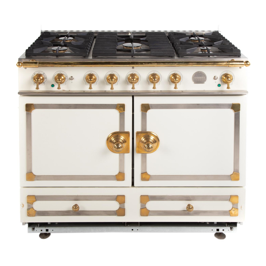
Range Overview Fig. 2.1 The 44” induction range (Fig. 2.1) has the following features: Fig. 2.2 A. 5 induction cooking zones B. Control panel C. Main multi-function oven D. Main fan oven E. Storage drawer Cooktop Use only pans that are suitable for induction cooktops. We recommend stainless steel, enamelled steel pans or cast iron pans with enamelled bases. -
Page 10: Cooktop Control Indications & Warnings
The very best pans have bases that are very slightly curved Fig. 2.4 up when cold (Fig. 2.4). If you hold a ruler across the bottom you will see a small gap in the middle. When they heat up the metal expands and lies flat on the cooking surface. - Page 11 Note: Using pans with a base diameter smaller than those Automatic heat-up time at Power level recommended will result in a power reduction. 100% (min:sec) 0:48 Residual Heat Indicator, H 2:24 After use, a cooking zone will remain hot for awhile as heat dissipates.
- Page 12 Low Temperature Setting, L1/L2 Power Level Maximum Operating Time L1 and L2 2 hours This function should only be used when heating from cold. 6 hours 6 hours Each cooking area is equipped with 2 low temperature 5 hours settings: 5 hours •...
-
Page 13: The Ovens
Overheat Function Fig. 2.10 This function identifies when the temperature of the pan rises rapidly and works to maintain a safe level of pan temperature. It should not interfere with normal cooking. Cookware with bases that become distorted (Fig. 2.2) when heated may interfere with the operation of the Overheat Function. - Page 14 Multi-function Oven Functions Fan Assisted Oven (Fig. 2.11) This function operates the fan, circulating air heated Defrost by the elements at the top and the base of the oven. This function operates the fan to circulate cold air The combination of fan and conventional cooking only.
- Page 15 Fan Ovens Fig. 2.12 Fan ovens circulate hot air continuously, which means faster, more even cooking. The recommended cooking temperatures for a fan oven are generally lower than those for a non-fan oven. Operating the Ovens Multi-function Oven The multi-function oven has two controls: a function control and a temperature control (Fig.
-
Page 16: Accessories
Accessories Fig. 2.16 Fig. 2.17 Oven Shelves Each cooker is supplied with: • 2 x Oven base tray (Fig. 2.16). • 2 x Flat shelves (Fig. 2.17). • 2 x Drop shelves (Fig. 2.18). • 2 x Deluxe oven tray (Fig. 2.19). Fig. -
Page 17: Telescopic Runners (Optional Extra)
Telescopic runners (Optional extra) Fig. 2.25 A glide-out oven shelf is available for the left-hand oven (Fig. 2.25). Note: The Handyrack must be removed before fitting the glide-out shelf. The rungs on the shelf supports are in pairs. The glide-out shelf runners can be fitted to any pair except the top. -
Page 18: Cooking Tips
Cooking Tips Hints on Using Your Induction Cooker General Oven Tips If you have not used an induction cooker before please be The wire shelves should always be pushed firmly to the back aware of the following: of the oven. •... -
Page 19: Cooking Table
Cooking table DocNo. 031-0004 - Cooking table - electric & fan single cavity The oven control settings and cooking times given in the table below are intended to be used as a guide only. Individual tastes may require the temperature to be altered to provide a preferred result. ArtNo.050-0019 - Albertine SC Food is cooked at lower temperature in a fan oven than in a conventional oven. -
Page 20: Cleaning Your Cooker
Cleaning your cooker Isolate the electricity supply before carrying out any Fig. 5.1 major cleaning. Then allow the cooker to cool. NEVER use paint solvents, washing soda, caustic cleaners, biological powders, bleach, chlorine based bleach cleaners, coarse abrasives or salt. DO NOT mix different cleaning products –... -
Page 21: To Remove Metal Rub-Off
To Remove Metal Rub-off Fig. 5.2 Sliding pans on the cooktop - especially aluminium or copper pans - can leave marks on the surface. These marks often appear like scratches, but can easily be removed using the procedure described previously for ‘Cleaning spills’... -
Page 22: Cleaning Table
Cleaning table Cleaners listed (Table 5.1) are available from supermarkets or electrical retailers as stated. For enamelled surfaces use a cleaner that is approved for use on vitreous enamel. Regular cleaning is recommended. For easier cleaning, wipe up any spillages immediately. Cooktop Part Finish... -
Page 23: Troubleshooting
Troubleshooting DocNo.050-0001 - Troubleshooting - Induction GENERIC Interference with and repairs to the hob MUST NOT My hob is scratched be carried out by unqualified persons. Do not try Always use the cleaning methods recommended in this to repair the hob as this may result in injury and guide, and make sure that the pan bottoms are smooth and damage to the hob. - Page 24 The oven light is not working Fig. 6.1 The bulb has probably blown. You can buy a replacement bulb (which is not covered under the guarantee) from most electrical stores. Ask for a 40 W - 230 V halogen lamp (G9) (Fig.
-
Page 25: Installation Instructions
Installation Instructions WARNING! The anti-tip device supplied with this range must be installed when the appliance is installed. This will reduce risk of tipping of the appliance from abnormal usage or by excessive loading of the oven door. WARNING! •... -
Page 26: Service And Parts
INSTALLATION Check the appliance is electrically safe when you have finished. Service and parts Firstly, please complete the appliance details below and keep them safe for future reference – this information will enable us to accurately identify the particular appliance and help us to help you. Filling this in now will save time and inconvenience if you later have a problem with the appliance. -
Page 27: Installation Safety Instructions
Refer to this manual. For assistance covering will withstand 180°F. (See the Installation or additional information, consult a qualified, Safety Instructions section). appointed La Cornue Service Agent. IMPORTANT - Make sure the wall coverings around IMPORTANT! your range can withstand the heat generated (up to 200°F) by the range. -
Page 28: Installation
INSTALLATION Check the appliance is electrically safe when you have finished. 10. Installation You will need the following equipment to complete the You will also need the following tools: range installation satisfactorily: Steel tape measure • Multimeter (for electrical checks). Cross-head screwdriver Flat-bladed screwdriver Spirit level... -
Page 29: Positioning The Range
INSTALLATION Check the appliance is electrically safe when you have finished. Positioning the Range Fig. 10.1 Fig. 10.1, Fig. 10.2 and Fig. 10.3 show the minimum recommended distance from the range to nearby combustible surfaces (see Table 10.1). We recommend a gap of no more than 3/16” (5 mm) (see Fig. -
Page 30: Moving The Range
INSTALLATION Check the appliance is electrically safe when you have finished. Moving the Range Fig. 10.5 On no account try and move the range while it is plugged into the electricity supply. The range is very heavy, so take great care. ... -
Page 31: Completing The Move
INSTALLATION Check the appliance is electrically safe when you have finished. Completing the Move Fig. 10.11 Unfold the rear edge of the cardboard base tray. Open the oven doors so that you can get a good grip on the bottom of the fascia panel as you move the oven (Fig. -
Page 32: Electrical Connection
INSTALLATION Check the appliance is electrically safe when you have finished. 11. Electrical connection Have your appliance properly installed and grounded by a qualified technician. The installation must conform with local codes, or in the absence of local codes, in accordance with the National Fuel Gas Code, ANSI Z223.1/NFPA 54 or, in Canada, the Natural Gas and Propane Installation Code, CSA B149.1 and in addition the National Electrical Code NFPA 70... - Page 33 INSTALLATION Check the appliance is electrically safe when you have finished. Connecting if the supplied cord and Fig. 11.1 plug is not suitable. To access the electrical connections, undo the screws and remove the electrical cover (Fig. 11.1). DISCONNECT THE ELECTRICAL SUPPLY. Fitting a 3-Wire Power Cord Disconnect the supplied power cord from the terminal block and ground post.
-
Page 34: Final Fitting And Checks
INSTALLATION Check the appliance is electrically safe when you have finished. 12. Final fitting and checks Assemble the range Fig. 12.1 Fig. 12.2 Installing the control knobs The range is supplied with 5 cooktop control knobs. These are for the induction controls to the left of the control panel (Fig. -
Page 35: Fitting The Drawer
INSTALLATION Check the appliance is electrically safe when you have finished. Fitting the drawer Removing the drawer... -
Page 36: Circuit Diagram
13. Circuit diagram Induction Hob Right Rear Left Front Left Rear Centre Center Right Front Interface board Cooktop Display Hob Display Induction unit 6 way connector 6 way connector Code Color Ground Blue Brown Black Orange Violet White Yellow Green/yellow Gray... -
Page 37: Oven
Oven Induction unit Connector Block Terminal Terminal Terminal Terminal Terminal Terminal Terminal Terminal Terminal Terminal Legend The connections shown in the circuit diagram are for single-phase. The ratings are for 240V, 60Hz; Component positions viewed from the front of the range. Code Description Code Description Code Color... -
Page 38: Technical Data
14. Technical Data INSTALLER: Please leave these instructions with the user. DATA BADGE LOCATION: Inside base drawer of cavity. Remove the drawer. COUNTRY OF DESTINATION: USA, Canada Connection ArtNo280-0090 Drawer Cavity & Badges Electric Supply 240 V 60 Hz Electric Rating 240V (2 Wire + N + Grd), 60Hz, 16.1 kW * Branch Circuit Protection 50 A *... -
Page 39: Warranty
The warranty applies even if you should move. All repair labor and replacement parts found to be defective due to materials and workmanship. LA CORNUE DOES NOT ASSUME ANY RESPONSIBILITY FOR INCIDENTAL OR CONSEQUENTIAL DAMAGES. Any damage due to transit must be reported within 15 days of delivery. - Page 40 CANADA Middleby Residential AGA Marvel 4960 Golden Parkway, SOFA Galleries Buford, GA 30518 6900 Airport Road 770-932-7282 Suite 205 www.lacornueusa.com Mississauga ONT L4V 1E8 Canada T.: 855-213-2785 F.: 905-678-4854 www.lacornue.com/ca www.agamarvel.com AGA CONSUMER PRODUCTS...
Need help?
Do you have a question about the CornuFe 44 and is the answer not in the manual?
Questions and answers