Table of Contents

Related Manuals for LawnMaster CLGT1018B


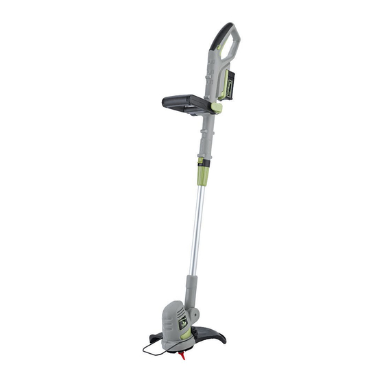
Summary of Contents for LawnMaster CLGT1018B
-
Page 1: Operators Manual
Operators Manual EN p. 2 18V-10" Li-On Cordless Grass Trimmer CLGT1018B Read all safety rules and instructions carefully before operating this tool. Distributed By Cleva North America 601 Regent Park Court Greenville, SC 29607 (866)-384-8432... -
Page 2: Table Of Contents
CONTENTS Contents Product Specifications General Safety Rules Electrical Information Symbols Know Your Cordless Grass Trimmer Assembly 8-12 Operation 13-18 Maintenance Troubleshooting Warranty Exploded View Parts List Notes PRODUCT SPECIFICATIONS 18V-10" Li-On Cordless Grass Trimmer Capacity Battery Pack 1.5 Ah Voltage Battery Pack 18 V d.c. -
Page 3: General Safety Rules
GENERAL SAFETY RULES WARNING Read and understand all instructions before using this product. Failure to follow all liquids, gases, or dust. Power tools create sparks which may ignite the dust or fumes. Do not allow children or untrained individuals to use this unit. Don’t expose power tools to rain or wet conditions. - Page 4 GENERAL SAFETY RULES Keep all parts of your body away from any moving parts and all hot surfaces of the unit. Do not put any object into openings. Do not use with any opening blocked; keep openings free Check the work area before each use. Remove all objects such as rocks, broken glass, nails, wire, or string which can be thrown or become entangled in the machine.
-
Page 5: Electrical Information
ELECTRICAL INFORMATION If the power supply cord is damaged, it must be replaced only by the manufacturer or by an authorized service center to avoid risk. Do not point the blower nozzle in the direction of people or pets. Never run the unit without the proper equipment attached. Always ensure the sweeper tubes are installed. -
Page 6: Symbols
SYMBOL S On the product, the rating label and within these instructions you will find among others he following symbols and abbreviations. Familiarise yourself with them to reduce hazards like personal injuries and damage to property. SYMBOL NAME DESIGNATION/EXPLANATION Volts Voltage Amperes Current... -
Page 7: Know Your Cordless Grass Trimmer
KNOW YOUR CORDLESS GRASS TRIMMER KNOW YOUR PRODUCT The safe use of this product requires an understanding of the information on the product and in this operator’s manual as well as a knowledge of the project you are attempting. Before use of this product, familiarize yourself with all operating features and safety rules. -
Page 8: Assembly
ASSEMBLY All referenced numbers are indicated on page 7. Attaching Guard (See fig. 1) Align the guard (14) with the trimmer head (19). Secure it by tightening the three mounting screws (15) with a screwdriver (Fig. 1). Fig.1 WARNING! Never use the product without the guard properly fitted. Attaching and Adjusting Auxiliary Handle (See figs. - Page 9 ASSEMBLY Fig.4 Fig.5 Fig.6 Fig.7 Fig.8 NOTE! Only tighten the quick release knob so that it is possible to clamp the lever down with light pressure. If the lever cannot be clamped, slightly loosen the quick release knob. If the lever can be clapped without resistance, tighten the quick release knob.
- Page 10 ASSEMBLY NOTE: This kind of trimming blade can be used from two sides. For the first replacemen turn the blade over and refit it. If both sides of a blade are worn out, replace with a new blade. Storage of cutting device (See fig. 12) Store the TrimFast cutting blades in the (16) storage compartment (7) found on the auxiliary handle (6).
- Page 11 ASSEMBLY Charging the Battery Pack (See figs. 15-16) before first use. WARNING! Always remove the battery pack from the product for charging! Charge in a safe location away from moisture, heat or any hazard to the charger or other danger! (Fig.
- Page 12 ASSEMBLY Charger Indicators Symbol Indicator lights (22) Status red, technical blinking defect red, connected to continuous power supply green, charging blinking fully green, charged continuous Battery LED Indicators (See figs. 17-18) indicator lights (25) Low capacity High Fig. 17 Fig. 18 Starting And Stopping...
-
Page 13: Operation
OPERATION Intended Use This grass trimmer CLGT1018B is with rated battery voltage of 18 V . 18LC01-ETL designates the respective charger with a charging voltage of 20.8 V The product is intended for cutting weed, grass or similar soft vegetation in areas that are hard to reach, e.g. - Page 14 OPERATION Adjusting Power Head Angle (See figs. 22-24) Adjust the angle of the trimmer head (19) according to the intended operation. 90° or 180° when trimming near edges and walls (Fig. 23, 24). Fig. 24 , 180° Fig. 22, initial position 0° Fig.
-
Page 15: General Operation
OPERATION Flower Guard (See figs. 28-29) Use the yoke to keep distance to obstacles that could be hit by the cutting device. Fig. 28 , working position Fig. 29 , storing position WARNING! Adjust the Flower Guard position only when the product is switched off and the cutting device is at a complete stop! General Operation use. - Page 16 OPERATION sensitive bark, and damage fence posts. thrown away from the work area (Fig. 30). Fig. 30 Fig.31 Fig.32 against the ground as this can ruin the lawn and damage the product (Fig. 33).
- Page 17 OPERATION Fig. 33 NOTE: Fig. 35 Fig. 34...
- Page 18 OPERATION After Use General Cleaning NOTE: Cutting Device WARNING! Guard Charger...
-
Page 19: Maintenance
MAINTENANCE Repair Storage Transportation... -
Page 20: Troubleshooting
TROUBLESHOOTING WARNING! Problem Possible cause Solution... -
Page 21: Warranty
WARRANTY... -
Page 22: Exploded View
EXPLODED VIEW... -
Page 23: Charger
PARTS LIST PART NO. PART DESCRPTION GE60DC.10.30 Left Handle FO1113.11.00 Charger GE60DC.20.00 Assistant Handle Assy GE60DC.00.01 Left Housing GE60DC.00.03 Left Decorating Cover GE60DC.10.01 Left Pivot Housing GE60DC.30.00 Rotate Housing TODXL1.78.UL Inner Cable GE50DC.30.00 Motor Assy GE60DC.40.00 Steel Flower Guard FG2101.01.01 Blade GE64DC.20.00 Safety Guard... - Page 24 NOTES...
Need help?
Do you have a question about the CLGT1018B and is the answer not in the manual?
Questions and answers