Table of Contents
Advertisement
Available languages
Available languages
Quick Links
Operator's Manual / Manual del Operador /
Manuel de l'opérateur
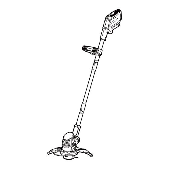
10" 24V MAX* Lithium-ion Cordless Grass Trimmer CLGT2410T
EN
Save this manual for future reference
* Maximum initial battery workload voltage (measured without a workload) is 24 volts.
Nominal voltage is 21.6 volts.
Podadora inalámbrica de 10" 24V MAX* de ión-litio CLGT2410T
ES
Guarde este manual para futuras referencias
* El voltaje máximo inicial de la carga de trabajo de la batería (medido sin carga de trabajo)
es de 24 voltios.El voltaje nominal es de 21.6 voltios.
FR
Conservez ce manuel pour toute référence ultérieure
* La tension initiale maximale de la batterie (mesurée sans charge de travail) est de 24 volts.
La tension nominale est de 21,6 volts.
Battery Model Number is
24LB4005-CN.
Charger Model Number is
24LFC14-ETL.
El número de modelo de la
batería es 24LB4005-CN.
El número de modelo del
cargador es 24LFC14-ETL.
Le numéro de modèle de la
batterie est 24LB4005-CN.
Le numéro de modèle du
chargeur est 24LFC14-ETL.
Read all safety rules and instructions carefully before operating this tool.
Distributed By: Suzhou Cleva Electric Appliance Co., Ltd.
NO.8 Ting Rong Street 215122 Suzhou - China
Lea atentamente todas las normas e instrucciones de seguridad antes de utilizar esta herramienta.
Distribuido por: Suzhou Cleva Electric Appliance Co., Ltd.
NO.8 Ting Rong Street 215122 Suzhou - China
Lisez attentivement toutes les règles de sécurité et les instructions avant d'utiliser cet outil.
Distribué par : Suzhou Cleva Electric Appliance Co., Ltd.
NO.8 Ting Rong Street 215122 Suzhou - Chine
Advertisement
Chapters
Table of Contents

Subscribe to Our Youtube Channel
Related Manuals for LawnMaster CLGT2410T


Summary of Contents for LawnMaster CLGT2410T
- Page 1 * Maximum initial battery workload voltage (measured without a workload) is 24 volts. Nominal voltage is 21.6 volts. Podadora inalámbrica de 10" 24V MAX* de ión-litio CLGT2410T Guarde este manual para futuras referencias * El voltaje máximo inicial de la carga de trabajo de la batería (medido sin carga de trabajo) es de 24 voltios.El voltaje nominal es de 21.6 voltios.
-
Page 2: Table Of Contents
Page TABLE OF CONTENTS SPECIFICATIONS IMPORTANT SAFETY INSTRUCTIONS SYMBOLS KNOW YOUR GRASS TRIMMER 9-10 ASSEMBLY 11-14 BATTERY PACK AND CHARGER 15-17 OPERATION 18-24 MAINTENANCE 25-27 ENVIRONMENTALLY SAFE BATTERY DISPOSAL TROUBLESHOOTING 29-30 ® LAWNMASTER WARRANTY EXPLODED VIEW PARTS LIST NOTES 34-35... -
Page 3: Specifications
SPECIFICATIONS 24V MAX* CORDLESS GRASS TRIMMER Type Cordless, Battery-powered No-load Speed 9200 RPM Line Diameter 0.065" (1.6 mm) Cutting Width 10" (250 mm) Unit Weight (With 4.0Ah Battery) 4.0 lbs (1.8 kg) BATTERY PACK Model Number 24LB4005-CN Rated Voltage of Battery 24 V Max* D.C Capacity of Battery 4.0 Ah... -
Page 4: Important Safety Instructions
IMPORTANT SAFETY INSTRUCTIONS WARNING Read and understand all instructions before using this product. injury. rubber gloves and substantial footwear is recommended when working outdoors. Wear protective hair covering to contain long hair. which it was designed. tired. when changing accessories such as cutting line, and so on. locked-up place, out of reach of children. - Page 5 IMPORTANT SAFETY INSTRUCTIONS proper instruction. switch is dangerous and must be repaired. or line which can be thrown or become entangled in the tool. BATTERY PACK ® 24LFC14-ETL, 24LFC02-ETL or 24LSC01- ETL chargers. pack. shock. explosion and possibly injury. eyes or skin. It may be toxic if swallowed. from the battery may cause irritation or burns.
- Page 6 IMPORTANT SAFETY INSTRUCTIONS parts. This will ensure that the safety of the product is maintained. BATTERY CHARGER ® 24LB4005-CN, 24LB4005-C, 24LB1304, 24LB2004, 24LB2605, or 24LB4005 lithium-ion batteries. of batteries may burst, causing personal injury or damage. If damaged, immediately discontinue use. Replace the charger with the identical unit as listed in the Parts List of this manual.
-
Page 7: Symbols
SYMBOLS Some of the following symbols may be used on this product. Please study them and learn their meaning. Proper interpretation of these symbols will allow you to operate the product better and safer. SYMBOL NAME DESIGNATION/EXPLANATION Volts Voltage Amperes Current Hertz Watts... - Page 8 SYMBOLS The following signal words and meanings are intended to explain the levels of risk associated with this product. SYMBOL SIGNAL MEANING Indicates an imminently hazardous situation, which, if not DANGER avoided, will result in death or serious injury. Indicates a potentially hazardous situation, which, if not WARNING avoided, could result in death or serious injury.
-
Page 9: Know Your Grass Trimmer
KNOW YOUR GRASS TRIMMER... - Page 10 KNOW YOUR GRASS TRIMMER Components 1.Main Handle 9.Debris Guard 17.Lock-off Switch 10.Trimming Line 18.Battery Charger 3.Battery Housing 11.Trimmer Head 19.Battery Pack 4.Upper Shaft 12.Flower Guard 20.Battery Release 5.Auxiliary Handle 13.Trimming Line Cut-Off Blade Button 6.Middle Shaft 14.Motor Housing 7.Lower Shaft 15.Shaft Locking Buttons 8.Pivot Button 16.Auxiliary Handle Adjustment Knob...
-
Page 11: Assembly
ASSEMBLY UNPACKING Carefully remove the product and any accessories from the box. Make sure that all items listed in the packing list are included. Inspect the product carefully to make sure no breakage or damage occurred during shipping. Do not discard the packing material until you have carefully inspected and satisfactorily operated the product. - Page 12 ASSEMBLY CONNECTING THE SHAFTS Insert the upper and lower shafts securely into the middle shaft and ensure the shaft locking buttons are fully engaged and locked into position (Fig. 1). Shaft Locking Buttons Fig. 1 FITTING THE DEBRIS GUARD 1. Align the debris guard with the trimmer head. 2.
- Page 13 ASSEMBLY ATTACHING THE AUXILIARY HANDLE 1. Loosen the auxiliary handle adjustment knob anti-clockwise and remove it from the auxiliary handle (Fig. 3). 2. Pull the ends of the auxiliary handle to extend the handle and slide it onto the handle support (Fig. 3). 3.
- Page 14 ASSEMBLY INSTALLING / REMOVING THE BATTERY PACK To install the battery pack: 1. Make sure the battery is fully charged. 2. Align the battery pack with the battery slot on the underside of the main handle, and then insert the battery pack into the handle (Fig.
-
Page 15: Battery Pack And Charger
BATTERY PACK AND CHARGER BATTERY CHARGING ® 1. Use only with 24V LawnMaster designed for the lithium-ion battery used in this tool. 2. Check the power voltage! Battery chargers operate on 120V. 3. The battery is charged between 40°F (4°C) and 100°F (38°C). This ensures an optimum battery service life. - Page 16 BATTERY PACK AND CHARGER the battery pack. If the LED status repeats a second time, try to charge another identical battery. If the battery charges normally, dispose of the defective battery pack (see Environmental Safe Battery Disposal section). normal), the charger may be defective. Replace with a new one. 6.
- Page 17 BATTERY PACK AND CHARGER WARNING If any part of the charger is missing or damaged, do not operate it! Replace the charger with a new one. Failure to heed this warning could result in possible serious injury. Check the voltage! The voltage must comply with the information on the rating label. 1.
-
Page 18: Operation
OPERATION INTENDED USE This trimmer is intended for cutting weed, grass or similar soft vegetation in areas that are hard to reach, e.g. under bushes, on slopes and edges. It must not be used to work on unusual thick, dry or wet grass, e.g. - Page 19 OPERATION ADVANCING THE TRIMMING LINE The trimmer features a fully automatic single line system. The line will automatically elongate every time you turn on the trimmer. NOTE: Bumping the head to try to advance the line will damage the trimmer and void the warranty. off switch until the line reaches the length of the trimming line cut-off blade.
- Page 20 OPERATION Fig. 10 PIVOTING HEAD 1. To pivot the head, push the pivot button and adjust the shaft to any of the 5 positions (Fig. 11). 2. Adjust the angle of the trimmer head according to the intended operation. 3. Release the button, make sure the shaft locks into place. 0°...
- Page 21 OPERATION WARNING Always ensure that the trimmer head engages into place! Only adjust to indicated angles. Never adjust to any other intermediate position! Fig. 12 Fig. 13 FLOWER GUARD WARNING the trimmer. Ensure that the trimmer head is at a complete stop.
- Page 22 OPERATION hit by the cutting device. Outer Position Inner Position Fig. 14 GENERAL OPERATION 1. Check the product, its battery pack, and charger as well as accessories for damage before each use. Do not use the product if it is damaged or shows wear. you keep your balance with your feet apart.
- Page 23 OPERATION 4. Pay attention when operating the tool close to trees and bushes. The cutting device can damage softer bark and fence posts. away from the trimmer head (Fig. 15). Fig. 15 6. Do not move the product too fast as this will result in ineffective cutting and possible damage. 7.
- Page 24 OPERATION 8. Keep the trimmer head at an angle of about 30° to the ground when trimming. Avoid pressing it against the ground as this can ruin the lawn and damage the product (Fig. 18). Fig. 18 NOTE: Let the cutting device do the work. Let it work at its own pace, never force it into the area to be cut.
-
Page 25: Maintenance
9. Pull the line extending from the eyelet so the line releases from the slot in the spool. 10.Reinstall the spool cover by depressing tabs into slot in the trimmer head and pushing down until spool cover clicks into place. ® NOTE: Use LawnMaster spool model # 121003116 for replacement. - Page 26 MAINTENANCE CAUTION After changing the spool, run the trimmer under no load (i.e. away from grass and weeds) for at least a minute to verify the line and the tool are both operating correctly. Use only the spool and line as recommended by the manufacturer.
- Page 27 MAINTENANCE and the outside edge of the spool. 6. Check the spool cover, spool, and spool base for wear. If necessary, replace the worn parts. 7. Install the spool in the trimmer head and replace the spool cover as described in SPOOL REPLACEMENT section.
-
Page 28: Environmentally Safe Battery Disposal
ENVIRONMENTAL SAFE BATTERY DISPOSAL The following toxic and corrosive materials are in the batteries used in this battery pack: lithium-ion, a toxic material. WARNING environment. Before disposing of damaged or worn-out lithium-ion battery packs, contact your local instructions. WARNING If the battery pack cracks or breaks, with or without leaks, do not recharge it and do not use it. Dispose of it and replace with a new battery pack. -
Page 29: Troubleshooting
TROUBLESHOOTING WARNING Only perform the steps described within these instructions! All further inspection, maintenance and repair work must be performed by an authorized service center Problem Possible Cause Solution Lock-off switch is not Press the lock-off switch and press the pressed. - Page 30 TROUBLESHOOTING The trimmer head is dirty. Clean the trimmer head. Battery pack capacity is Charge the battery pack. Unsatisfactory result. too low. Cutting tall grass at ground Cut the tall grass from the top down to level. prevent wrapping. The trimming line is worn, Install more trimming line.
-
Page 31: Warranty
® LAWNMASTER WARRANTY ® product carries a limited two (2) year warranty against defects in workmanship and materials from date of purchase under normal household use. If product is to be used for commercial, industrial or rental use, a 30 day limited warranty will apply. -
Page 32: Exploded View
EXPLODED VIEW... -
Page 33: Parts List
PARTS LIST Key Number Part Number Description Quantity Main Handle Assembly Switch Trigger Assembly Safe-Locking Button Assembly Micro Switch Board Assembly Upper Shaft Assembly Middle Shaft Assembly Lower Shaft Assembly Base Auxiliary Handle Assembly Motor Assembly Spool Cover Assembly 121003116 Spool With Line Spool Cover Motor Housing Assembly... -
Page 34: Notes
NOTES... - Page 35 NOTES...
-
Page 37: Índice
FAMILIARÍCESE CON SU PODADORA 10-11 MONTAJE 12-15 PAQUETE DE BATERÍAS Y CARGADOR 16-18 OPERACIÓN 19-26 MANTENIMIENTO 27-30 ELIMINACIÓN DE BATERÍAS RESPETUOSA CON EL MEDIO AMBIENTE SOLUCIÓN DE PROBLEMAS 32-34 ® GARANTÍA DE LAWNMASTER VISTA EXPLOTADA LISTA DE PIEZAS NOTAS 38-39... -
Page 38: Especificaciones
ESPECIFICACIONES 24V MÁX* PODADORA DE CÉSPED INALAMBRÍCA Tipo Inalámbrica, funciona con baterías Velocidad sin carga 9200 RPM Diámetro de línea 0.065" (1.6 mm) Ancho de corte. 10" (250 mm) Peso (Sin la Batería 4.0Ah) 4.0 lbs (1.8 kg) PAQUETE DE BATERÍAS Número de modelo 24LB4005-CN Voltaje nominal de la batería... -
Page 39: Instrucciones De Seguridad Importantes
INSTRUCCIONES DE SEGURIDAD IMPORTANTES ¡ADVERTENCIA! LEA TODAS LAS INSTRUCCIONES ANTES DE UTILIZAR ESTE PRODUCTO. Si no se siguen todas las instrucciones indicadas a continuación, pueden producirse descargas eléctricas, incendios o lesiones personales graves. mojadas. libre. Use una cobertura protectora para el cabello para contener el cabello largo. mantenimiento, cuando cambie accesorios como la línea de corte, etc. - Page 40 INSTRUCCIONES DE SEGURIDAD IMPORTANTES explosión o riesgo de lesiones. instrucción adecuada. calientes de la unidad. de aire. PAQUETE DE BATERÍAS ® 24LFC14-ETL, 24LFC02-ETL o 24LSC01-ETL. descarga eléctrica. Puede ser tóxico si se ingiere. o electríca. Para reducir el riesgo de lesiones personales, nunca utilice ningún producto inalámbrico inmediato atención médica.
- Page 41 INSTRUCCIONES DE SEGURIDAD IMPORTANTES puedan conectar una terminal a otra. Si se produce un cortocircuito entre los terminales de la o a temperaturas superiores a 265 °F (130 °C) puede provocar una explosión. producto. CARGADOR DE LA BATERÍA ® para baterías de iones de litio 24LB4005-CN, 24LB4005-C, 24LB1304, 24LB2004, 24LB2605, or 24LB4005.
- Page 42 INSTRUCCIONES DE SEGURIDAD IMPORTANTES interferencias con una o varias de las siguientes medidas: GUARDE ESTAS INSTRUCCIONES presta este aparato a alguien, préstele también estas instrucciones.
-
Page 43: Símbolos
SIMBOLOS SÍMBOLO NOMBRE DESIGNACIÓN/EXPLICACIÓN Voltios Voltaje Amperios Corriente Hercios Frecuencia (cíclos por segundo) Vatios Alimentación Minutos Tiempo Corriente alterna Tipo de corriente Corriente directa Tipo o característica de la corriente. …/min Por minuto órbitas, etc., por minuto. Alerta de condiciones No la exponga a la lluvia ni la opere sobre suelo de humedad mojado. - Page 44 SIMBOLOS riesgo asociados con este producto. SYMBOLE SEÑAL SIGNIFICATION PELIGRO evita, provocará la muerte o lesiones graves. ADVERTENCIA evita, podría provocar la muerte o lesiones graves. PRECAUCIÓN evita, podría provocar la muerte o lesiones graves. (Sin símbolo de alerta de seguridad) Indica una situación AVISO SERVICIO idénticas.
-
Page 45: Familiarícese Con Su Podadora
FAMILIARÍCESE CON SU PODADORA... - Page 46 FAMILIARÍCESE CON SU PODADORA Componentes 1. Manija principal 8. Botón de giro 16.Manija auxiliar Perilla 2. Botón de encendido 9. Resguardo contra escombros de ajuste / apagado 10.Línea de poda 17.Interruptor de 3. Carcasa para la 11. Cabezal de poda batería 18.Cargador de la 4.
-
Page 47: Montaje
MONTAJE DESEMPACADO satisfactoriamente el producto. 384-8432). NECESITARÁ (ARTÍCULOS NO SUMINISTRADOS) LISTA DE EMPAQUE (1) Manija principal (1) Resguardo contra escombros (1) Manija Auxiliar (con perilla de ajuste de manija auxiliar instalada) (1) Manual del Operador (1) 24V 2.5A Cargador de baterías (compartidas con la podadora) ADVERTENCIA remplazadas. - Page 48 MONTAJE CONEXIÓN DE LOS EJES los ejes Fig 1 MONTAJE DEL PROTECTOR PARA ESCOMBROS 2. Alinee el protector para escombros con el cabezal de corte. 2. Asegure el protector para escombros apretando los 3 tornillos de montaje con un destornillador (Fig. 2). ADVERTENCIA protección, evite el contacto con la cuchilla.
- Page 49 MONTAJE FIJACIÓN DE LA MANIJA AUXILIAR retírela de la manija auxiliar (Fig. 3). (Fig. 3). 3. Ajuste la manija auxiliar a la posición de operación deseada. Manija de Soporte Fig 3 apretar con fuerza moderada. Si la siente demasiado apretada, gire la perilla de ajuste de la manija Fig 4...
- Page 50 MONTAJE INSTALACIÓN /RETIRADA DEL PAQUETE DE BATERÍAS Para instalar el paquete de baterías: NOTA: la manija de la podadora antes de iniciar la operación. Para retirar el paquete de baterías: 1. Detenga la podadora de césped. Figure 5 Figure 6...
-
Page 51: Paquete De Baterías Y Cargador
PAQUETE DE BATERÍAS Y CARGADOR BATERIA CARGANDO ® de 24 V. El cargador de batería suministrado 2. Compruebe el voltaje de alimentación! Los cargadores de baterías operan con 120 V. la batería. períodos prolongados. 5. La batería se entrega parcialmente cargada. Para garantizar la capacidad total de la batería, batería. - Page 52 PAQUETE DE BATERÍAS Y CARGADOR cargador de baterías cargará automáticamente. instalar la batería. Si el estado del LED se repite por segunda vez, intente cargar otra batería idéntica. Eliminación de baterías de forma segura para el medio ambiente). nueva. PANEL LED DE LA BATERÍA LED mostrarán los niveles de carga.
- Page 53 PAQUETE DE BATERÍAS Y CARGADOR ADVERTENCIA 2. Conecte el cargador a la fuente de alimentación. fuente de alimentación. NOTA: funcionamiento. ¡Siempre cargue la batería antes de almacenarla!
-
Page 54: Operación
OPERACIÓN USO PREVISTO Esta podadora está concebida para cortar maleza, hierba o vegetación blanda similar en zonas de trabajar hierba poco espesa, seca o húmeda, por ejemplo, hierba de pasto, ni para triturar hojas. Este producto está destinado únicamente para uso doméstico privado, no para uso comercial. No INTERRUPTOR DE ENCENDIDO/APAGADO ADVERTENCIA ¡Riesgo de lesiones! No opere el producto sin el depósito de escombros. - Page 55 OPERACIÓN AVANCE DE LA LÍNEA DE RECORTE La podadora cuenta con un sistema de una sola línea totalmente automática. La línea se alargará NOTA: garantía. 1. Con la podadora funcionando pero NO podando, suelte el interruptor de encendido/apagado. la cuchilla de corte de la línea de corte. 3.
- Page 56 OPERACIÓN MANIJA AUXILIAR reloj. 2. Gire la manija auxiliar a la posición de operación deseada. La manija auxiliar puede deslizarse (Fig. 10). 3. Apriete la perilla de ajuste de la manija auxiliar girándola en el sentido de las manecillas del reloj. Fig 10 CABEZAL GIRATORIO 11).
- Page 57 OPERACIÓN BORDES El eje inferior se puede torcer cuando se trabaja con bordes. Ajuste el ángulo del cabezal de poda según la operación prevista. protector para escombros como se muestra (Fig. 12). en el sentido de las agujas del reloj para rebordear (Fig. 13). ADVERTENCIA indicados.
- Page 58 OPERACIÓN RESGUARDO PARA FLORES ADVERTENCIA en su lugar (Fig. 14). 14). Posición Exterior Posición Interior Fig 14 OPERACIÓN GENERAL producto se detenga por completo antes de dejarlo. 6. No trabaje demasiado. Tome descansos regulares para asegurarse de poder concentrarse en el...
- Page 59 OPERACIÓN PODA ADVERTENCIA extraída del producto. Fig 15...
- Page 60 OPERACIÓN Fig 16 Fig 17 8. Mantenga el cabezal de corte en un ángulo de aproximadamente 30° con respecto al suelo al (Fig. 18). Fig 18...
- Page 61 OPERACIÓN NOTA: Deje que el dispositivo de corte haga el trabajo. Déjalo actuar a su propio ritmo, nunca fuerce la zona a cortar. dispositivo de corte no entre en contacto con plantas frágiles (Fig. 19). Fig 19 Fig 20 ANTES DE USAR...
-
Page 62: Mantenimiento
MANTENIMIENTO ADVERTENCIA ajustar, inspeccionar o limpiar la podadora de césped. LIMPIEZA 1. Limpie el producto con un trapo seco. Utilice un cepillo para las zonas de difícil acceso. en agua las salidas de aire. 3. Elimine el polvo persistente con aire a alta presión (máx. 3 bar). NOTA: No utilice detergentes o desinfectantes químicos, alcalinos, abrasivos u otros agresivos a utilizar el producto. - Page 63 MANTENIMIENTO ® NOTA: modelo # 121003116 para el remplazo. PRECAUCIÓN Cubierta de la bobina Bobina Fig 21 REEMPLAZO DE LA LÍNEA NOTA: 3. Corte un trozo de línea de aproximadamente 16.4 pies, (5 m) largo. bobina. Enrolle la línea alrededor de la bobina en el sentido de las agujas del reloj, como indican...
- Page 64 MANTENIMIENTO Ranura anclaje Fig 22 (152 mm) extendidos más allá de la ranura. No la llene demasiado. Después de enrollar la línea, bobina. necesario, reemplace las piezas desgastadas. la sección REEMPLAZO DE LA BOBINA. ALMACENAMIENTO 2. Limpie el producto como se describe a continuación. TRANSPORTACIÓN 3.
- Page 65 MANTENIMIENTO MANTENIMIENTO DEL PAQUETE DE BATERÍAS 1. ¡Siempre cargue completamente la batería antes de almacenarla! de la batería. desconecte el cargador del tomacorriente. MANTENIMIENTO DEL CARGADOR cavidad empotrada o en los contactos. Limpie con un trapo seco. No use solventes, agua, ni colocarlo en condiciones húmedas.
-
Page 66: Eliminación De Baterías Respetuosa Con El Medio Ambiente
ELIMINACIÓN DE BATERÍAS SIN PELIGRO PARA EL MEDIO AMBIENTE iones de litio, un material tóxico. ADVERTENCIA póngase en contacto con su agencia local de eliminación de residuos o con la Agencia de Protección ADVERTENCIA ¡NO INTENTE REPARARLO! Para evitar lesiones y riesgos de incendio, explosión o descarga eléctrica, y para evitar daños al medio ambiente: •... -
Page 67: Solución De Problemas
SOLUCIÓN DE PROBLEMAS mismo. puede solucionar rápidamente. ADVERTENCIA ¡Realice únicamente los pasos descritos en estas instrucciones! usted mismo! PROBLEMA POSIBLE CAUSA SOLUCIÓN presione el interruptor de encendido/ no está presionado. apagado para encender la podadora. La batería no está asegurada. El producto no se inicia La batería no está... - Page 68 SOLUCIÓN DE PROBLEMAS PROBLEMA POSIBLE CAUSA SOLUCIÓN La línea de podado está Reemplace la línea de podado. Consulte la sección SUSTITUCIÓN DE LÍNEA. Línea de podado Instale más línea. Consulte la sección SUSTITUCIÓN DE LÍNEA. podado hacia el exterior a través del La línea de podado no está...
- Page 69 SOLUCIÓN DE PROBLEMAS PROBLEMA POSIBLE CAUSA SOLUCIÓN Limpie los contactos de la batería Los contactos de la batería están contaminados. batería. El enchufe del cargador Inserte completamente el enchufe de de baterías no está alimentación en la toma de corriente. conectado correctamente.
-
Page 70: Garantía De Lawnmaster
® GARANTÍA DE LAWNMASTER ® la fecha de compra en condiciones de uso doméstico normal. Si el producto se va a utilizar para Las baterías tienen una garantía de un año contra defectos de mano de obra y materiales. Las baterías válidas. -
Page 71: Vista Explotada
VISTA EXPLOTADA... -
Page 72: Lista De Piezas
LISTA DE PIEZAS Número Número de pieza Descripción Cantidad clave Conjunto de manija principal. Conjunto de interruptor de gatillo. Microinterruptor Conjunto de placa Conjunto del eje superior Conjunto del eje central Conjunto de eje inferior Base Conjunto de manija auxiliar Conjunto del motor Conjunto de la cubierta de la bobina 121003116... -
Page 73: Notas
NOTAS... - Page 74 NOTAS...
- Page 76 SPÉCIFICATIONS CONSIGNES DE SÉCURITÉ IMPORTANTES SYMBOLES CONNAÎTRE SON COUPE-HERBE 10-11 ASSEMBLAGE 12-15 BLOC-BATTERIE ET CHARGEUR 16-18 OPÉRATION 19-26 ENTRETIEN 27-30 RECYCLAGE DES BATTERIES DANS LE RESPECT DE L'ENVIRONNEMENT DÉPANNAGE 32-34 ® GARANTIE LAWNMASTER VUE ÉLARGIE LISTE DES PIÈCES REMARQUES 38-39...
-
Page 77: Spécifications
SPÉCIFICATIONS COUPE-HERBE SANS FIL 24V MAX* Type Vitesse à vide 9200 RPM Diamètre de la ligne 1,6 mm (0,065") Largeur de coupe 254 mm (10") Poids (sans batterie 4,0Ah) 1,8 kg (4,0 livres) BLOC-BATTERIE Numéro du modèle 24LB4005-CN Tension nominale de la batterie 24 V Max* D.C. -
Page 78: Consignes De Sécurité Importantes
CONSIGNES DE SÉCURITÉ IMPORTANTES AVERTISSEMENT! Lisez et comprenez toutes les instructions avant d'utiliser ce produit. Le non-respect de toutes les instructions énumérées ci-dessous peut entraîner un choc électrique, un incendie et/ou des blessures graves. humides ou mouillés. protecteur pour contenir les cheveux longs. l'opération est poussiéreuse. - Page 79 CONSIGNES DE SÉCURITÉ IMPORTANTES bloc-batterie peut entraîner un risque de blessure et d'incendie. ou un risque de blessure. avoir reçu les instructions nécessaires. chaudes de l'appareil. obstruée ; évitez les accumulations de poussière, de peluches, de cheveux et de tout ce qui pourrait réduire le débit d'air.
- Page 80 CONSIGNES DE SÉCURITÉ IMPORTANTES savon. Si le liquide entre en contact avec vos yeux, rincez-les à l'eau claire pendant au moins 10 minutes, puis consultez immédiatement un médecin. Le respect de cette règle réduira le risque de blessures graves. connecter d'une borne à l'autre. La mise en court-circuit des bornes des piles peut provoquer des le risque d'incendie.
- Page 81 CONSIGNES DE SÉCURITÉ IMPORTANTES deux conditions suivantes : REMARQUE : une installation résidentielle. des mesures suivantes: - Réorientez ou déplacez l'antenne de réception. - Augmentez la distance entre l'équipement et le récepteur. récepteur. - Consultez le revendeur ou un technicien radio/télévision expérimenté pour obtenir de l'aide. CONSERVEZ CES INSTRUCTIONS...
-
Page 82: Symboles
SYMBOLES SYMBOLE DÉSIGNATION/EXPLICATION Volts Tension Ampères Courant Hertz Fréquence (cycles par seconde) Watts Puissance Minutes Temps Type de courant Courant continu Type ou caractéristique de courant. …/min Par minute par minute. Alerte aux conditions N'exposez pas à la pluie et ne l'utilisez pas dans des humides endroits humides. - Page 83 SYMBOLES de risque associés à ce produit. SYMBOLE SIGNAL SIGNIFICATION Indique une situation dangereuse imminente qui, si elle n'est DANGER pas évitée, entraînera la mort ou des blessures graves. Indique une situation potentiellement dangereuse qui, si elle AVERTISSEMENT n'est pas évitée, peut entraîner la mort ou des blessures graves.
-
Page 84: Connaître Son Coupe-Herbe
CONNAÎTRE SON COUPE-HERBE... - Page 85 CONNAÎTRE SON COUPE-HERBE Composants 1. Poignée principale 8. Bouton de pivotement 16.Bouton de réglage de 2. Interrupteur marche/ 9. Pare-débris la poignée auxiliaire 10.Fil de coupe 17.Interrupteur de 3. Boîtier de batterie verrouillage 4. Arbre supérieur 18.Chargeur de batterie 5. Poignée auxiliaire 19.Bloc-batterie 6.
-
Page 86: Assemblage
ASSEMBLAGE DÉBALLAGE Retirez soigneusement le produit et les accessoires de la boîte. Assurez-vous que tous les éléments énumérés dans la liste d'emballage sont inclus. Inspectez soigneusement le produit pour vous assurer qu'il n'a pas été cassé ou endommagé pendant le transport. Si des pièces sont endommagées ou manquantes, veuillez appeler le service à... - Page 87 ASSEMBLAGE RACCORDEMENT DES ARBRES boutons de verrouillage de l'arbre sont complètement engagés et verrouillés en position (Figure 1). Boutons de verrouillage de l'arbre Figure 1 MONTAGE DU PARE-DÉBRIS 2. Fixez le pare-débris en serrant les 3 vis de montage à l'aide d'un tournevis (Figure 2). AVERTISSEMENT La lame de coupe de la ligne de coupe située sur le pare-débris est tranchante.
- Page 88 ASSEMBLAGE FIXATION DE LA POIGNÉE AUXILIAIRE 1. Desserrez le bouton de réglage de la poignée auxiliaire dans le sens inverse des aiguilles d'une montre et retirez-le de la poignée auxiliaire (Figure 3). poignée (Figure 3). 3. Réglez la poignée auxiliaire dans la position d'utilisation souhaitée. Support de la poignée Figure 3...
- Page 89 ASSEMBLAGE INSTALLATION / RETRAIT DU BLOC-BATTERIE Pour installer le bloc-batterie : 1. Assurez-vous que la batterie est complètement chargée. principale, puis insérez le bloc-batterie dans la poignée (Figure 5). REMARQUE : du coupe-herbe avant de commencer à utiliser l'appareil. Pour retirer le bloc-batterie : batterie de la poignée (Figure 6).
-
Page 90: Bloc-Batterie Et Chargeur
BLOC-BATTERIE ET CHARGEUR CHARGEUR DE BATTERIE ® spécialement conçu pour la batterie lithium-ion utilisée dans cet outil. de la batterie. 4. Protégez la batterie de la chaleur, d'une exposition continue au soleil, et tenez-la éloignée des radiations ou d'autres sources de chaleur. Ne laissez pas la batterie dans l'outil en plein soleil pendant de longues périodes. - Page 91 BLOC-BATTERIE ET CHARGEUR a) L'une des conditions possibles est que la température de la batterie ne se situe pas dans la plage de est atteinte, le chargeur de batterie se met automatiquement en charge. b) Si la plage de température est correcte et que le clignotement de la DEL rouge se poursuit, retirez et sur l'élimination des batteries dans le respect de l'environnement).
- Page 92 BLOC-BATTERIE ET CHARGEUR AVERTISSEMENT qu'elle s'enclenche (Figure 7). 2. Branchez le chargeur sur l'alimentation électrique. l'alimentation électrique. 4. Appuyez sur le bouton de libération du-bloc batterie et retirez-le du chargeur. REMARQUE :...
- Page 93 FONCTIONNEMENT USAGE PRÉVU Ce coupe-herbe est conçu pour couper les mauvaises herbes, l'herbe et la végétation tendre similaire Ce produit est conçu pour un usage domestique privé et non pour un usage commercial. Il ne doit pas MISE EN MARCHE/ARRÊT AVERTISSEMENT oreilles.
- Page 94 FONCTIONNEMENT AVANCEMENT DE LA LIGNE DE COUPE Le coupe-herbe est doté d'un système de ligne unique entièrement automatique. La ligne s'allonge REMARQUE : herbe et annulera la garantie. coupe de la ligne de coupe. 3. Reprendre la coupe. Réglage manuel de la longueur de la ligne : de la ligne.
- Page 95 FONCTIONNEMENT POIGNÉE AUXILIAIRE 1. Desserrez le bouton de réglage de la poignée auxiliaire en le tournant dans le sens inverse des aiguilles d'une montre. 2. Tournez la poignée auxiliaire dans la position souhaitée. La poignée auxiliaire peut coulisser de 3. Serrez le bouton de réglage de la poignée auxiliaire dans le sens des aiguilles d'une montre. Figure 10 TÊTE PIVOTANTE positions (Figure 11).
- Page 96 FONCTIONNEMENT COUPE EN BORDURE (Figure 12). AVERTISSEMENT Figure 12 Figure 13...
- Page 97 FONCTIONNEMENT PARE-FLEURS AVERTISSEMENT Position extérieure Position intérieure Figure 14 FONCTIONNEMENT GÉNÉRAL accessoires, ne sont pas endommagés. N'utilisez pas le produit s'il est endommagé ou usé. endommager le produit. travail et maîtriser pleinement le produit.
- Page 98 FONCTIONNEMENT COUPE AVERTISSEMENT tomber. est retirée de l'appareil. l'endommager. Figure 15...
Need help?
Do you have a question about the CLGT2410T and is the answer not in the manual?
Questions and answers