Table of Contents
Advertisement
Quick Links
Advertisement
Table of Contents

Subscribe to Our Youtube Channel
Related Manuals for Supero SUPERSERVER 7043M-8


Summary of Contents for Supero SUPERSERVER 7043M-8
- Page 1 ® UPER 7043M-8 UPER ERVER 7043M-6 UPER ERVER USER’S MANUAL 1.0a...
- Page 2 Supermicro's total liability for all claims will not exceed the price paid for the hardware product. Unless you request and receive written permission from SUPER MICRO COMPUTER, you may not copy any part of this document. Information in this document is subject to change without notice. Other products and companies referred to herein are trademarks or registered trademarks of their respective companies or mark holders.
-
Page 3: Preface
Preface About This Manual This manual is written for professional system integrators and PC technicians. It provides information for the installation and use of the SuperServer 7043M-8/ 7043M-6. Installation and maintainance should be performed by experienced technicians only. The SuperServer 7043M-8/7043M-6 is a high-end, dual processor 4U tower/... - Page 4 Chapter 4: System Safety You should thoroughly familiarize yourself with this chapter for a general overview of safety precautions that should be followed when installing and servicing the SuperServer 7043M-8/7043M-6. Chapter 5: Advanced Motherboard Setup Chapter 5 provides detailed information on the X5DMS-8GM/X5DMS-6GM motherboard, including the locations and functions of connections, headers and jumpers.
- Page 5 Preface Notes...
-
Page 6: Table Of Contents
UPER ERVER 7043M-8/7043M-6 Manual Table of Contents Preface About This Manual ....................... iii Manual Organization ....................iii Chapter 1: Introduction Overview ......................1-1 Motherboard Features ..................1-2 Server Chassis Features ................1-4 Contacting Supermicro ................... 1-6 Chapter 2: Server Installation Overview ...................... - Page 7 Table of Contents Chapter 4: System Safety Electrical Safety Precautions ................. 4-1 General Safety Precautions ................4-2 ESD Safety Precautions ................. 4-3 Operating Precautions ..................4-4 Chapter 5: Advanced Motherboard Setup Handling the X5DMS-8GM/X5DMS-6GM Motherboard ......... 5-1 PGA Processor and Heatsink Installation ............ 5-2 Connecting Cables ..................
- Page 8 UPER ERVER 7043M-8/7043M-6 Manual Third Power Supply Fail Header ............5-16 Keylock ....................5-17 Wake-On-LAN ..................5-17 Wake-On-Ring ..................5-17 Jumper Settings ..................... 5-18 Explanation of Jumpers ................5-18 CMOS Clear .................... 5-18 Main Power Override ................5-18 Mb LAN Enable/Disable ................. 5-19 Gb LAN Enable/Disable .................
- Page 9 Table of Contents Chapter 7: BIOS Introduction ....................... 7-1 Running Setup ....................7-2 Main BIOS Setup .................... 7-2 Advanced Setup ....................7-6 Security ......................7-15 Power ......................7-17 Boot ......................... 7-19 PIR ........................7-20 Exit ........................7-22 Appendices: Appendix A: BIOS POST Messages ............... A-1 Appendix B: BIOS POST Codes ................
- Page 10 UPER ERVER 7043M-8/7043M-6 Manual Notes...
-
Page 11: Chapter 1: Introduction
Chapter 1 Introduction Overview The Supermicro SuperServer 7043M-8/7043M-6 is a high-end dual processor server that can be utilized either in a tower or in a rackmount configuration. The SuperServer 7043M-8/7043M-6 is comprised of two main subsystems: the SC742S-450 high-end server chassis and the X5DMS-8GM/X5DMS-6GM dual Xeon processor mainboard. -
Page 12: Motherboard Features
Motherboard Features At the heart of the SuperServer 7043M-8/7043M-6 lies the X5DMS-8GM/X5DMS- 6GM, a dual processor motherboard based on Intel's E7501 chipset and designed to provide maximum performance. Below are the main features of the X5DMS- 8GM/X5DMS-6GM. - Page 13 Chapter 1: Introduction PCI Expansion Slots The X5DMS-8GM/X5DMS-6GM has a total of six PCI expansion slots consisting of one 64-bit 133 MHz slot, two 64-bit 66 MHz slots and three 32-bit 33 MHz slots. See Chapter 7 for details. Onboard Controllers/Ports One floppy drive controller and two onboard ATA/100 controllers are provided to support up to four hard drives or ATAPI devices.
-
Page 14: Server Chassis Features
UPER ERVER 7043M-8/7043M-6 Manual Server Chassis Features The SuperServer 7043M-8/7043M-6 is a high-end, scaleable server platform de- signed with today's most state-of-the-art features. The following is a general outline of the main features of the SC742S-450 server chassis. System Power The 7043M-8/7043M-6 features a single 450W power supply with a redundant cooling fan and a thermal control feature. - Page 15 Chapter 1: Introduction I/O Backplane The SC742 is an ATX form factor chassis that can be used as a tower or mounted as a 4U rackmount server. The I/O backplane provides seven motherboard expansion slots, one COM ports, a parallel port, a video (monitor) port, two USB ports, PS/2 mouse and keyboard ports, one G-bit and one M-bit Ethernet ports.
-
Page 16: Contacting Supermicro
UPER ERVER 7043M-8/7043M-6 Manual Contacting Supermicro Headquarters Address: SuperMicro Computer, Inc. 980 Rock Ave. San Jose, CA 95131 U.S.A. Tel: +1 (408) 503-8000 Fax: +1 (408) 503-8008 Email: marketing@supermicro.com (General Information) support@supermicro.com (Technical Support) W e b Site: www.supermicro.com Europe Address: SuperMicro Computer B.V. -
Page 17: Chapter 2: Server Installation
Server Installation 2-1 Overview This chapter provides a quick setup checklist to get your SuperServer 7043M-8/ 7043M-6 up and running. Following these steps in the order given should enable you to have the system operational within a minimum amount of time. This quick setup assumes that your SuperServer 7043M-8/7043M-6 system has come to you with the processors and memory preinstalled. -
Page 18: Choosing A Setup Location
UPER ERVER 7043M-8/7043M-6 Manual Choosing a Setup Location: - Leave enough clearance in front of the system to enable you to open the front door completely (~25 inches). - Leave approximately 30 inches of clearance in the back of the system to allow for sufficient airflow and ease in servicing. -
Page 19: Installing The 7043M-8/7043M-6 Into A Rack
Chapter 2: Server Installation Installing the 7043M-8/7043M-6 into a Rack This section provides information on installing the SuperServer 7043M-8/7043M- 6 into a rack unit. If the 7043M-8/7043M-6 has already been mounted into a rack or if you are using it as a tower, you can skip ahead to Sections 2-5 and 2-6. -
Page 20: Installing The Chassis Rails
UPER ERVER 7043M-8/7043M-6 Manual Installing the Chassis Rails: You will need to remove the top cover, the top/left cover and the feet to add rack rails to the chassis. First, remove the top/left cover by pushing the release tab in the center of the cover lip while pushing the cover toward the rear of the chassis (see Figure 2-2). -
Page 21: Installing The Rack Rails
Installing the Rails to the Chassis Installing the Rack Rails: Determine where you want to place the SuperServer 7043M-8/7043M-6 in the rack. (See Rack and Server Precautions in Section 2-3.) Position the fixed rack rail/sliding rail guide assemblies at the desired location in the rack, keeping the sliding rail guide facing the inside of the rack. -
Page 22: Installing The Server Into The Rack
UPER ERVER 7043M-8/7043M-6 Manual Installing the Server into the Rack: You should now have rails attached to both the chassis and the rack unit. The next step is to install the server into the rack. Do this by lining up the rear of the chassis rails with the front of the rack rails. -
Page 23: Checking The Motherboard Setup
Chapter 2: Server Installation Checking the Motherboard Setup After setting up the the 7043M-8/7043M-6, you will need to open the unit to make sure the motherboard is properly installed and all the connections have been made. 1. Accessing the inside of the 7043M-8/7043M-6 (see Figure 2-6): (If rack mounted, first release the retention screws that secure the unit to the rack. - Page 24 UPER ERVER 7043M-8/7043M-6 Manual Figure 2-6. Accessing the Inside of the 7043M-8/7043M-6...
-
Page 25: Checking The Drive Bay Setup
Chapter 2: Server Installation Checking the Drive Bay Setup Next, you should check to make sure the peripheral drives and the SCSI drives and SCA backplane have been properly installed and all connections have been made. 1. Accessing the drive bays: All drives can be accessed from the front of the server. - Page 26 UPER ERVER 7043M-8/7043M-6 Manual 6. Supplying power to the system: The last thing you must do is to provide input power to the system. Plug the power cord from the power supply units into a high-quality power strip that offers protection from electrical noise and power surges. It is recommended that you use an uninterruptible power supply (UPS).
-
Page 27: Chapter 3: System Interface
Chapter 3: System Interface Chapter 3 System Interface Overview There are several LEDs on the control panel as well as two for each SCSI drive carrier and LAN (Ethernet) port. These LEDs are to keep you con- stantly informed of the overall status of the system and the activity and health of specific components. -
Page 28: Reset
Power: Indicates external power is being supplied to the system's power supply unit. This LED should normally be illuminated when the system is oper- ating. HDD: Indicates IDE channel activity. On the SuperServer 7043M-8/7043M- 6, this LED indicates CD-ROM drive activity when flashing. NIC1 NIC1: Indicates network activity on LAN1 when flashing. -
Page 29: Overheat
Chapter 3: System Interface Overheat: Indicates a processor overheat condition. This may be caused by cables obstructing the airflow in the system or the ambient room temperature being too warm. You should also check to make sure that the chassis covers are installed and that all fans are present and operating normally. -
Page 30: Lan (Ethernet) Port Leds
UPER ERVER 7043M-8/7043M-6 Manual LAN (Ethernet) Port LEDs The Gb and the Mb LAN (Ethernet) ports both have two LEDs, which are used to give connectivity status as shown below. The yellow (left) LED flashes to indicate activity while the other (right) LED may flash green or orange to indicate the speed of the connection (there is no orange indica- tion on the Mb port). -
Page 31: Chapter 4: System Safety
Electrical Safety Precautions Basic electrical safety precautions should be followed to protect yourself from harm and the SuperServer 7043M-8/7043M-6 from damage: ! Be aware of the locations of the power on/off switch on the chassis as well as the room's emergency power-off switch, disconnection switch or electrical outlet. -
Page 32: General Safety Precautions
General Safety Precautions Follow these rules to ensure general safety: ! Keep the area around the SuperServer 7043M-8/7043M-6 clean and free of clutter. ! The SuperServer 7043M-8/7043M-6 weighs approximately 46 lbs. (20.9 kg.) when fully loaded. When lifting the system, two people at either end should lift slowly with their feet spread out to distribute the weight. -
Page 33: Esd Safety Precautions
Chapter 4: System Safety ! After accessing the inside of the system, close the system back up and (if rackmounted) secure it to the rack unit with the retention screws after ensuring that all connections have been made. ESD Precautions Electrostatic discharge (ESD) is generated by two objects with different electrical charges coming into contact with each other. -
Page 34: Operating Precautions
UPER ERVER 7043M-8/7043M-6 Manual ! For grounding purposes, make sure your computer chassis provides excellent conductivity between the power supply, the case, the mounting fasteners and the motherboard. Operating Precautions Care must be taken to assure that all chassis covers are in place when the 7043M-8/7043M-6 is operating to ensure proper cooling. -
Page 35: Chapter 5: Advanced Motherboard Setup
Chapter 5: Advanced Motherboard Setup Chapter 5 Advanced Motherboard Setup This chapter covers the steps required to install processors and heatsinks to the X5DMS-8GM/X5DMS-6GM motherboard, connect the data and power cables and install add-on cards. All motherboard jumpers and connections are described and a layout and quick reference chart are included in this chapter. -
Page 36: Pga Processor And Heatsink Installation
UPER ERVER 7043M-8/7043M-6 Manual PGA Processor and Heatsink Installation When handling the processor package, avoid placing direct pressure on the label area of the fan. Also, do not place the motherboard on a conductive surface, which can damage the BIOS battery and prevent the system from booting up. IMPORTANT: Always connect the power cord last and always remove it before adding, removing or changing any hardware components. - Page 37 Chapter 5: Advanced Motherboard Setup 4. Apply the proper amount of thermal compound to the CPU die and place the heatsink on top of the CPU. Make sure the heatsink sits completely flat on the CPU. If not completely flat, the space between the two will degrade the heat dissipation function of the heatsink, which may cause the proces- sor to overheat.
- Page 38 UPER ERVER 7043M-8/7043M-6 Manual Figure 5-2a. Retention Clips (left: 603-pin, right: 604-pin) Figure 5-2b. Heatsink Installation (different motherboard s h o w n )
-
Page 39: Connecting Cables
Chapter 5: Advanced Motherboard Setup Connecting Cables Now that the processors are installed, the next step is to connect the cables to the board. These include the data (ribbon) cables for the periph- erals and control panel and the power cables. Connecting Data Cables The ribbon cables used to transfer data from the peripheral devices have been carefully routed in preconfigured systems to prevent them from block-... -
Page 40: Connecting The Control Panel
UPER ERVER 7043M-8/7043M-6 Manual Connecting the Control Panel JF2 contains header pins for various front control panel connectors. Figure 5-3 for the pin locations of the various front control panel buttons and LED indicators. Please note that even and odd numbered pins are on opposite sides of each header. -
Page 41: I/O Ports
Chapter 5: Advanced Motherboard Setup I/O Ports The I/O ports are color coded in conformance with the PC 99 specification. See Figure 5-4 below for the colors and locations of the various I/O ports. Figure 5-4. Rear Panel I/O Ports Mouse Parallel Port (Burgundy) (Green) - Page 42 UPER ERVER 7043M-8/7043M-6 Manual Memory Support The X5DMS-8GM/X5DMS-6GM can support up to 12 GB of ECC registered DDR266/200 (PC2100/1600) SDRAM memory. PC100/133 SDRAM is not sup- ported. Figure 5-5a. Side View of DIMM Installation into Slot To Install: Insert module vertically and press down until it snaps into place.
-
Page 43: Adding Pci Cards
Chapter 5: Advanced Motherboard Setup Adding PCI Cards 1. PCI expansion slots: The X5DMS-8GM/X5DMS-6GM system board has one 64-bit 133 MHz and two 64-bit 66 MHz PCI-X slots and three 32-bit 33 MHz PCI slots. The backplane of the 7043M-8/7043M-6 has seven I/O slots that allows you to have a full complement of PCI cards installed on the system. -
Page 44: Motherboard Details
UPER ERVER 7043M-8/7043M-6 Manual Motherboard Details Figure 5-7. SUPER X5DMS-8GM/X5DMS-6GM Layout (not drawn to scale) ® UPER X5DMS-6GM Keyboard ATX PWR CONN CH FAN3 JP40 Mouse CH FAN1 DIMM #1A USB 0/1 BANK 1 JP36 DIMM #1B COM1 CPU 1 DIMM #2A BANK 2 DIMM #2B... -
Page 45: X5Dms-8Gm/X5Dms-6Gm Quick Reference
Chapter 5: Advanced Motherboard Setup X5DMS-8GM/X5DMS-6GM Quick Reference Jumper Description Default Setting JBT1 CMOS Clear See Section 5-9 JPA1/JPA2 SCSI CH A/B Termination Open (Enabled) JP3/JD3 Mb/Gb LAN Enable/Disable Pins 1-2 (Enabled) VGA Enable/Disable Pins 1-2 (Enabled) 3rd P/S Fail Alarm En/Dis Open (Disabled) JP22 SCSI Enable/Disable... -
Page 46: Connector Definitions
UPER ERVER 7043M-8/7043M-6 Manual Connector Definitions ATX Power Connector ATX Power Supply 24-pin Connector Pin Definitions Pin Number Definition Pin Number Definition The X5DMS-8GM/X5DMS-6GM +3.3V +3.3V power supply connector meets the +3.3V -12V SSI (Superset ATX) 24-pin specifi- PS_ON# cation, however it also supports a 20- pin power supply connector. -
Page 47: Hdd Led
Chapter 5: Advanced Motherboard Setup HDD LED H DD LED Pin Definitions (JF2) The HDD LED (for IDE Hard Disk Number Definition Drives) connection is located on pins 13 and 14 of JF2. Attach the HD Active IDE hard drive LED cable to these pins to display disk activity. -
Page 48: Reset Button
UPER ERVER 7043M-8/7043M-6 Manual Reset Button Reset Pin Definitions (JF2) The Reset Button connection is lo- Number Definition cated on pins 3 and 4 of JF2. At- Reset tach it to the hardware reset Ground switch on the computer case. Refer to the table on the right for pin definitions. -
Page 49: Extra Universal Serial Bus Headers
Chapter 5: Advanced Motherboard Setup Extra Universal Serial Bus Headers USB 2 Pin USB3 Pin Definitio ns (J13) Definitions (J14) Extra USB headers (FPUSB0/1 and USB2) included Number Definition Number Definition Power Power motherboard. FPUSB0/1 were de- signed to provide front side USB Ground Ground access. -
Page 50: Fan Headers
UPER ERVER 7043M-8/7043M-6 Manual Fan Headers Fan H eader Pin Definitions The motherboard has several fan Number Definition headers designated CPU1 Chassis Ground (black) Fan, CPU2 Chassis Fan, Chassis +12V (red) Tachometer Fan3, Chassis Fan4 and Chassis Caution: These fan headers Fan5. -
Page 51: Keylock
Chapter 5: Advanced Motherboard Setup Keylock The keyboard lock connection is lo- cated on JP35. Utilizing this header allows you to inhibit any actions made on the keyboard, effectively "locking" it. Wake-On-LAN The Wake-On-LAN header is des- W ake-On-LAN Pin Definitions (W OL) ignated WOL. -
Page 52: Jumper Settings
UPER ERVER 7043M-8/7043M-6 Manual Jumper Settings Explanation of Jumpers Connector Pins To modify the operation of the motherboard, jumpers can be used choose between optional Jumper settings. Jumpers create shorts between two pins to change the function of the connector. Pin 1 is Setting identified with a square solder pad Pin 1-2 short... -
Page 53: Mb Lan Enable/Disable
Chapter 5: Advanced Motherboard Setup Mb LAN Mb LAN Enable/Disable Enable/Disable Jumper Settings (JP3) Change the setting of jumper JP3 to Jumper Position Definition enable or disable the Mb LAN port on Pins 1-2 Enabled the motherboard (see Figure 5-4 for Pins 2-3 Disabled location). -
Page 54: Scsi Enable/Disable
UPER ERVER 7043M-8/7043M-6 Manual SCSI Enable/Disable SCSI Enable/Disable Jumper Settings The SCSI Termination jumper at (JP22) Jumper JP22 allows you to enable or dis- Position Definition able the onboard SCSI controller. Pins 1-2 Enabled Pins 2-3 Disabled The normal (default) position is on pins 1-2 to enable SCSI termina- tion. -
Page 55: System Bus Speed
Chapter 5: Advanced Motherboard Setup System Bus Speed System Bus Speed Jumper Settings (JP39) JP39 allows you to select Auto, 400 Jumper Position Definition or 533 MHz for your system (front Pins 1-2 Auto side) bus speed. The recommended Pins 2-3 400 MHz Open 533 MHz... -
Page 56: Parallel Port, Floppy/Hard Drive And Scsi Connections
UPER ERVER 7043M-8/7043M-6 Manual 5-11 Parallel Port, Floppy/Hard Disk Drive and SCSI Connections Note the following when connecting the floppy and hard disk drive cables: • The floppy disk drive cable has seven twisted wires. • A red mark on a wire typically designates the location of pin 1. •... -
Page 57: Floppy Connector
Chapter 5: Advanced Motherboard Setup Floppy Connector The floppy connector is located on JP7. See the table below for pin definitions. F loppy Connector Pin Definitions (JP7) Pin Number Function Pin Number Function FD HDIN Reserved FD EDIN Index- Motor Enable Drive Select B- Drive Select A- Motor Enable... -
Page 58: Ultra320/160 Scsi Connectors
UPER ERVER 7043M-8/7043M-6 Manual Ultra320/160 SCSI Connectors Refer to the table below for the pin definitions of the Ultra320 (7043M-8) or Ultra160 SCSI connectors (7043M- 6) located at JA1 and JA2. Ultra320/160 SCSI Connectors (JA1 and JA2) Connector Connector Contact Contact Number Signal Names... -
Page 59: 5-12 Installing Software Drivers
Chapter 5: Advanced Motherboard Setup 5-12 Installing Software Drivers After all the hardware has been installed you must install the software drivers. The necessary drivers are all included on the Supermicro CD that came packaged with your motherboard. After inserting this CD into your CD-ROM drive, the display shown in Figure 5-8 should appear. - Page 60 UPER ERVER 7043M-8/7043M-6 Manual Notes 5-26...
-
Page 61: Chapter 6: Advanced Chassis Setup
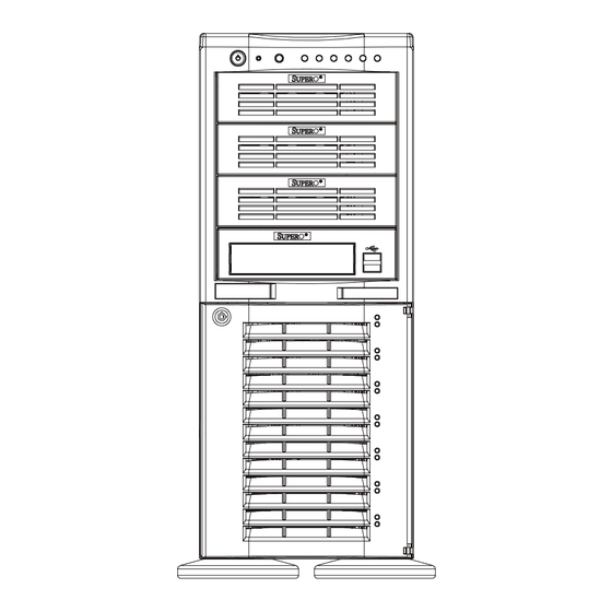
Chapter 6: Advanced Chassis Setup Chapter 6 Advanced Chassis Setup This chapter covers the steps required to install components and perform simple maintenance on the SC742 chassis. Following the component instal- lation steps in the order given will eliminate most common problems. If some steps are unnecessary, skip ahead to the step that follows. - Page 62 UPER ERVER 7043M-8/7043M-6 Manual Figure 6-1. Chassis Front View Main Power NMI Button System Reset System LEDs 5 1/4" Drive Bays Floppy Drive Front Side USB Front Bezel Lock SCSI Drive Configuration Drive#6 Drive#5 Drive#4 SCSI Drive Bays Drive#3 Drive#2 Drive#1 Drive#0 SCSI Active LED...
-
Page 63: Front Control Panel
Chapter 6: Advanced Chassis Setup Front Control Panel The front control panel must be connected to the JF2 connector on the mother- board to provide you with system status and alarm indications. A ribbon cable has bundled these wires together to simplify this connection. Connect the cable from JF2 on the motherboard (making sure the red wire plugs into pin 1) to the appropriate comnnector on the front control panel PCB (printed circuit board). -
Page 64: System Fans
UPER ERVER 7043M-8/7043M-6 Manual System Fans Two 9-cm chassis cooling fans located between the motherboard and the drive bays provide cool air intake for the system. A heavy duty 12-cm exhaust fan at the rear of the chassis pulls the cooling air through the system and expels the hot air. -
Page 65: Drive Bay Installation
Chapter 6: Advanced Chassis Setup Figure 6-3. Removing the 12-cm Exhaust Fan Drive Bay Installation A bezel covers the front of the chassis but does not need to be removed to access the drives. If you wish to remove the bezel piece, push on the three tabs on the inside left side lip of the front chassis cover. - Page 66 UPER ERVER 7043M-8/7043M-6 Manual Installing/removing hot-plug SCSI drives: The seven SCSI drive carriers are all easily accessible at the front of the chassis. The SCSI drives are hot-pluggable, meaning they can be removed and installed without powering down the system. To remove a carrier, first open the front bezel then push the release button located beside the drive LEDs.
- Page 67 Chapter 6: Advanced Chassis Setup SCSI backplane: All seven SCSI drives plug into the SCSI backplane (p/n SCA742). The 7043M-8 provides single channel, Ultra320 operation while the 7043M-6 provides single channel, Ultra160 operation. There are no jumpers on the SCSI backplane. A ribbon cable from JA1 on the motherboard should be connected to the LVD1 connector on the SCSI backplane.
-
Page 68: Installing Components In The 5 1/4" Drive Bays
UPER ERVER 7043M-8/7043M-6 Manual Installing Components in the 5 1/4" Drive Bays Drive bay configuration The 7043M-8/7043M-6 has four 5 1/4" drive bays above the SCSI drive bays. Components such as a floppy drive, IDE hard drives, CD-ROM drives or additional SCSI drives (that can fit into a standard IDE drive bay) can be installed in these 5 1/4"... -
Page 69: Power Supply
Chapter 6: Advanced Chassis Setup Power Supply The 7043M-8/7043M-6 has a single 450 watt redundant cooling power supply. The redundant cooling function is provided by two fans. The primary fan operates continuously and the secondary fan (along with an alarm and an LED) activate if either 1) the primary fan fails or 2) a temperature threshold is exceeded. - Page 70 UPER ERVER 7043M-8/7043M-6 Manual Notes 6-10...
-
Page 71: Chapter 7: Bios
Chapter 7: BIOS Chapter 7 BIOS Introduction This chapter describes the PhoenixBIOS™ Setup utility for the X5DMS-8GM/ X5DMS-6GM. The Phoenix ROM BIOS is stored in a flash chip and can be easily upgraded using a floppy disk-based program. Note: Due to periodic changes to the BIOS, some settings may have been added or deleted and might not yet be recorded in this manual. -
Page 72: Running Setup
UPER ERVER 7043M-8/7043M-6 Manual Running Setup *Default settings are in bold text unless otherwise noted. The BIOS setup options described in this section are selected by choos- ing the appropriate text from the main BIOS Setup screen. All displayed text is described in this section, although the screen display is often all you need to understand how to set the options (see on next page). -
Page 73: Main Bios Setup Menu
Chapter 7: BIOS Main BIOS Setup Menu Phoenix BIOS Setup Utility Main Advanced Security Power Boot Exit Item Specific Help System Time [16:19:20] System Date [02/02/02] Legacy Diskette A: [1.44/1.25 MB] Legacy Diskette B: [Not Installed] ! Primary Master [120 GB] ! Primary Slave [None] ! Secondary Master... - Page 74 UPER ERVER 7043M-8/7043M-6 Manual Legacy Diskette A This setting allows the user to set the type of floppy disk drive installed as diskette A. The options are Disabled, 360Kb 5.25 in, 1.2MB 5.25 in, 720Kb 3.5 in, 1.44/1.25MB, 3.5 in and 2.88MB 3.5 in. Legacy Diskette B This setting allows the user to set the type of floppy disk drive installed as diskette B.
- Page 75 Chapter 7: BIOS Type Selects the type of IDE hard drive. The options are Auto (allows BIOS automatically determine the hard drive's capacity, number of heads, etc.), a number from 1-39 to select a predetermined type of hard drive, CD-ROM and ATAPI Removable. Multi-Sector Transfers Select the number of transfer sectors.
-
Page 76: Advanced Setup
UPER ERVER 7043M-8/7043M-6 Manual Advanced Setup Choose Advanced from the Phoenix BIOS Setup Utility main menu with the arrow keys. You should see the following display. The items with a triangle beside them have sub menus that can be accessed by highlighting the item and pressing <Enter>. - Page 77 Chapter 7: BIOS ! ! ! ! ! PCI/PnP Configuration Access the submenu for this item to make changes to the PCI/PnP configuration, as listed below. Onboard LAN1 OPROM Configure Enabling this setting allows you to boot your system from LAN 1. Options are Enabled and Disabled.
- Page 78 UPER ERVER 7043M-8/7043M-6 Manual ! ! ! ! ! PCI Slot Configuration PCI/PCIX Frequency (Slot 4-5) This setting controls the bus speed of PCI-X slots # 4 and 5. Options are 33 MHz, 66 MHz, 100 MHz, 133 MHz and Auto. Note that the onboard SCSI limits the speed of these two slots to 66 MHz on the X5DMS-8GM/ X5DMS-6GM.
- Page 79 Chapter 7: BIOS Latency Timer This setting (included in the submenu for the above six settings) sets the minimum guaranteed time slice allotted to the bus master in units of PCI bus clocks. Options are Default, 0020h, 0040h, 0060h, 0080h, 00A0h, 00C0h and 00E0h.
- Page 80 UPER ERVER 7043M-8/7043M-6 Manual Serial Port A This setting allows you to assign control of serial port A. The options are Enabled (user defined), Disabled, Auto (BIOS controlled) and OS Controlled. Base I/O Address Select the base I/O address for serial port A. The options are 3F8, 2F8, 3E8 and 2E8.
- Page 81 Chapter 7: BIOS Base I/O Address Select the base I/O address for the parallel port. The options are 378, 278 and 3BC. Interrupt Select the IRQ (interrupt request) for the parallel port. Options are IRQ5 and IRQ7. Mode Specify the parallel port mode. Options are Output Only, Bi-directional, EPP and ECP.
- Page 82 UPER ERVER 7043M-8/7043M-6 Manual SMART Device Monitoring This setting lets you enable or disable SMART device monitoring, which may predict IDE drive failure. The options are Enabled and Disabled. ECC Configuration This setting lets you enable or disable ECC (Error Correction and Checking). The options are ECC and Disabled.
- Page 83 Chapter 7: BIOS Split Lock Operations This setting allows you to Enable or Disable split lock operations. Hyper-Threading This setting allows you to Enable or Disable hyper-threading. Enabling hyper- threading results in increased CPU performance. ! ! ! ! ! DMI Event Logging Access the submenu to make changes to the following settings.
- Page 84 UPER ERVER 7043M-8/7043M-6 Manual This setting will clear all DMI event logs when set to Yes. Options are Yes and No. ! ! ! ! ! Console Redirection Access the submenu to make changes to the following settings. COM Port Address Specifies to redirect the console to On-board COMA or On-board COMB.
-
Page 85: Security
Chapter 7: BIOS Security Choose Security from the Phoenix BIOS Setup Utility main menu with the arrow keys. You should see the following display. Security setting options are displayed by highlighting the setting using the arrow keys and pressing <Enter>. All Security BIOS settings are described in this section. - Page 86 UPER ERVER 7043M-8/7043M-6 Manual Set Supervisor Password When the item "Set Supervisor Password" is highlighted, hit the <Enter> key. When prompted, type the Supervisor's password in the dialogue box to set or to change supervisor's password, which allows access to BIOS. Set User Password When the item "Set User Password"...
-
Page 87: Power
Chapter 7: BIOS Power Choose Power from the Phoenix BIOS Setup Utility main menu with the arrow keys. You should see the following display. Power setting options are displayed by highlighting the setting using the arrow keys and pressing <Enter>. All Power BIOS settings are described in this section. - Page 88 UPER ERVER 7043M-8/7043M-6 Manual Suspend Timeout Use this setting to specify the period of system inactivity to transpire before entering the suspend state. Options are Off, 5 min, 10 min, 15 min, 20 min, 30 min, 40 min and 60 min. Resume on Time Select either Off or On, which will wake the system up at the time specified in the next setting.
-
Page 89: Boot
Chapter 7: BIOS Boot Choose Boot from the Phoenix BIOS Setup Utility main menu with the arrow keys. You should see the following display. Highlighting a setting with a + or - willl expand or collapse that entry. See details on how to change the order and specs of boot devices in the Item Specific Help window. -
Page 90: Pir
UPER ERVER 7043M-8/7043M-6 Manual Choose PIR from the Phoenix BIOS Setup Utility main menu with the arrow keys. You should see the following display. The items with a triangle beside them have sub menus that can be accessed by highlighting the item and pressing <Enter>. PIR stands for "Processor Info ROM", which allows BIOS to read certain information from the processors. - Page 91 Chapter 7: BIOS ! ! ! ! ! Processor Info ROM Data Highlight this and hit <Enter> to see PIR data on the following items: Header Info Processor Data Processor Core Data L3 Cache Data Package Data Part Number Data Thermal Reference Data Feature Data Other Data...
-
Page 92: Exit
UPER ERVER 7043M-8/7043M-6 Manual 3.3V Standby (V) 3.3V Vcc (V) 5V Vcc (V) 12V Vcc (V) 1.8V Vcc (V) -12V Vcc (V) Exit Choose Exit from the Phoenix BIOS Setup Utility main menu with the arrow keys. You should see the following display. All Exit BIOS settings are described in this section. - Page 93 Chapter 7: BIOS Exit Saving Changes Highlight this item and hit <Enter> to save any changes you made and to exit the BIOS Setup utility. Exit Discarding Changes Highlight this item and hit <Enter> to exit the BIOS Setup utility without saving any changes you may have made.
- Page 94 UPER ERVER 7043M-8/7043M-6 Manual Notes 7-24...
-
Page 95: Appendix A: Bios Post Messages
Appendix A: BIOS POST Messages Appendix A BIOS POST Messages During the Power-On Self-Test (POST), the BIOS will check for problems. If a problem is found, the BIOS will activate an alarm or display a message. The following is a list of such BIOS messages. - Page 96 UPER ERVER 7043M-8/7043M-6 Manual System CMOS checksum bad - Default configuration used System CMOS has been corrupted or modified incorrectly, perhaps by an application program that changes data stored in CMOS. The BIOS installed Default Setup Values. If you do not want these values, enter Setup and enter your own values.
- Page 97 Appendix A: BIOS POST Messages System cache error - Cache disabled RAM cache failed and BIOS disabled the cache. On older boards, check the cache jumpers. You may have to replace the cache. See your dealer. A disabled cache slows system performance considerably. CPU ID: CPU socket number for Multi-Processor error.
- Page 98 UPER ERVER 7043M-8/7043M-6 Manual Fixed Disk n Fixed disk n (0-3) identified. Invalid System Configuration Data Problem with NVRAM (CMOS) data. I/O device IRQ conflict I/O device IRQ conflict error. PS/2 Mouse Boot Summary Screen: PS/2 Mouse installed. nnnn kB Extended RAM Passed Where nnnn is the amount of RAM in kilobytes successfully tested.
- Page 99 Appendix A: BIOS POST Messages Parity Check 2 nnnn Parity error found in the I/O bus. BIOS attempts to locate the address and display it on the screen. If it cannot locate the address, it displays ????. Press <F1> to resume, <F2> to Setup, <F3> for previous Displayed after any recoverable error message.
- Page 100 UPER ERVER 7043M-8/7043M-6 Manual Notes...
-
Page 101: Appendix B: Bios Post Codes
Appendix B: BIOS POST Codes Appendix B BIOS POST Codes This section lists the POST (Power On Self Test) codes for the PhoenixBIOS. POST codes are divided into two categories: recoverable and terminal. Recoverable POST Errors When a recoverable type of error occurs during POST, the BIOS will display an POST code that describes the problem. - Page 102 UPER ERVER 7043M-8/7043M-6 Manual POST Code Description 8254 timer initialization 8237 DMA controller initialization Reset Programmable Interrupt Controller 1-3-1-1 Test DRAM refresh 1-3-1-3 Test 8742 Keyboard Controller Set ES segment register to 4 GB Auto size DRAM Initialize POST Memory Manager Clear 512 kB base RAM 1-3-4-1 RAM failure on address line xxxx* 1-3-4-3 RAM failure on data bits xxxx* of low byte of...
- Page 103 Appendix B: BIOS POST Codes POST Code Description Test RAM between 512 and 640 kB Test extended memory Test extended memory address lines Jump to UserPatch1 Configure advanced cache registers Initialize Multi Processor APIC Enable external and CPU caches Setup System Management Mode (SMM) area Display external L2 cache size Load custom defaults (optional) Display shadow-area message...
- Page 104 UPER ERVER 7043M-8/7043M-6 Manual POST Code Description Check for SMART Drive (optional) Shadow option ROMs Set up Power Management Initialize security engine (optional) Enable hardware interrupts Determine number of ATA and SCSI drives Set time of day Check key lock Initialize typematic rate Erase F2 prompt Scan for F2 key stroke...
- Page 105 Appendix B: BIOS POST Codes POST Code Description Re-map I/O and memory for PCMCIA Initialize digitizer and display message Unknown interrupt The following are for boot block in Flash ROM POST Code Description Initialize the chipset Initialize the bridge Initialize the CPU Initialize system timer Initialize system I/O Check force recovery boot...
- Page 106 UPER ERVER 7043M-8/7043M-6 Manual Notes...
-
Page 107: Appendix C: Supero Doctor Iii
Appendix C: Supero Doctor III Appendix C Supero Doctor III Overview The Supero Doctor III program is a Web-based management tool that supports remote management capability and includes both Remote and Local Manage- ment tools. The local management is called the SD III Client. The Supero Doctor III program included on the CD-ROM that came with your motherboard allows you to monitor the environment and operations of your system. - Page 108 UPER ERVER 7043M-8/7043M-6 Manual Linux Support The SD III Client and Supero Doctor II for Linux support the following features:* Applications for local management Pager and E-mail alerts SNMP support Health Monitoring CPU and system temperatures System voltages CPU and chassis fans Chassis intrusion Redundant power failure (hardware dependant) Note: For Linux operating systems, please refer to the Supero Doctor II informa-...
- Page 109 Appendix C: Supero Doctor III Figure C-2. Supero Doctor III Remote Power/Reset Control Screen Note: SD III software can be downloaded from our website at ftp:// ftp.supermicro.com/utility/Supero_Doctor_III/. You can also download the SDIII User's Guide at http://www.supermicro.com/PRODUCT/Manuals/SDIII/ UserGuide.pdf. For Linux, we recommend the use of Supero Doctor II. Please refer to our Supero Doctor II information posted at ftp://ftp.supermicro.com/utility/ Supero_Doctor_II/Linux/.
- Page 110 UPER ERVER 7043M-8/7043M-6 Manual Notes...
-
Page 111: Appendix D: System Specifications
Appendix D: System Specifications Appendix D System Specifications Processors ® Single or dual 603/604-pin Intel Xeon processors to 3.20 GHz at a front side (system) bus speed of 533/400 MHz Note: Please refer to the support section of our web site for a complete listing of supported processors. - Page 112 UPER ERVER 7043M-8/7043M-6 Manual Motherboard 7043M-8: X5DMS-8GM (Extended ATX form factor) 7043M-6: X5DMS-6GM (Extended ATX form factor) Dimensions (both boards): 12" x 13.05" (305 x 330 mm) Chassis Model: SC742S-450 Form Factor: 4U rackmount or tower Dimensions: 17.1" x 7" x 24.2" (434 x 178 x 615 mm) Weight Net (Bare Bone): ~46 lbs.
- Page 113 Appendix D: System Specifications Regulatory Compliance Electromagnetic Emissions: FCC Class B, EN 55022 Class B, EN 61000- 3-2 & -3-3, CISPR 22 Class B Electromagnetic Immunity: EN 55024/CISPR 24, (EN 61000-4-2, EN 61000-4-3, EN 61000-4-4, EN 61000-4-5, EN 61000-4-6, EN 61000-4-8, EN 61000-4-11) Safety: EN 60950/IEC 60950-Compliant UL Listed (USA), CUL Listed (Canada), TUV Certified (Germany), CE...
- Page 114 UPER ERVER 7043M-8/7043M-6 Manual Notes...
Need help?
Do you have a question about the SUPERSERVER 7043M-8 and is the answer not in the manual?
Questions and answers