Table of Contents
Advertisement
Advertisement
Table of Contents

Related Manuals for Invacare Auriga


Summary of Contents for Invacare Auriga
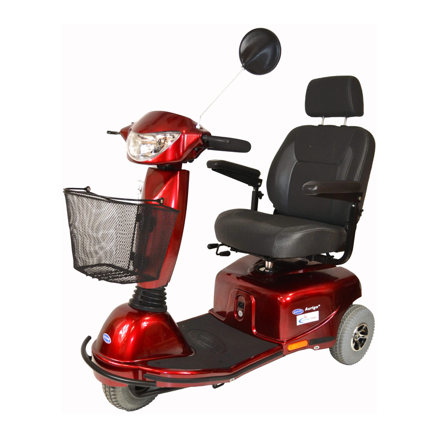
- Page 1 Invacare ® Auriga Service Manual 6 / 10 km/h version...
- Page 2 ® How to get in touch with Invacare If you have any questions or need support, please contact your authorised Invacare® Dealer fi rst. He has the necessary know-how and equipment plus the special knowledge concerning your Invacare® product which enables him to offer you all-round satisfactory service. Should you wish to contact us directly, you can reach us in Europe at the following: Invacare®...
- Page 3 • Any alterations to the Scooter which occur as a result of incorrectly or improperly performed maintenance work will lead to the exclusion of all liability on the part of INVACARE. • If you have any problems or questions please contact INVACARE TECHNICAL SERVICES...
- Page 4 Auriga Service Manual Invacare ® Notes on transport • If the Scooter has to be shipped back to the manufacturer for major repairs, you should always use the original packaging for transport. • You should also include as accurate a fault description as possible. The following symbols are used in...
-
Page 5: Table Of Contents
Auriga Service Manual Invacare ® Table of contents Page Safety and assembly instructions Before any inspection or repair work During dismantling/reassembly Before operation / after completion of work Tool list Layout of modules, components, displays and controls Inspection plan Operational faults... - Page 6 Auriga Service Manual Invacare ® 9.7.5 Replacing a fuse 9.7.6 Hand-held programmer Tiller linking assembly / control panel 9.8.1 Steering column 9.8.2 Tiller Replacing the keypad and the control panel 9.9.1 Assembling / disassembling the steering column shroud 9.9.2 Replacing the Bowden Cable 9.9.3...
-
Page 7: Safety And Assembly Instructions
Auriga Service Manual Invacare ® Safety and assembly instructions These safety instructions are intended to prevent accidents, and it is imperative that they are observed. Before any inspection or repair work • Read and observe this Service Manual and the associated operating manual. -
Page 8: Before Operation / After Completion Of Work
Auriga Service Manual Invacare ® 1.3. Before operation / after completion of work Caution: • Check all fi xings for tight fi t. • Check all parts for correct interlocking. • Only operate Scooter with correct tyre pressure (2.5 bar). -
Page 9: Tool List
Auriga Service Manual Invacare ® Tool list You will need a standard tool set with at least the following: • Set of open and ring spanners • Set of Allen-keys • Torque wrench • Socket spanner set • Set of screwdrivers •... -
Page 10: Layout Of Modules, Components, Displays And Controls
Auriga Service Manual Invacare ® Layout of modules, components, displays and controls The following fi gures show the layout of scooter modules. Removal and reassembly of spare parts is described in Chapter 9. 1) De-clutching lever 2) Release lever for swivelling and... -
Page 11: Inspection Plan
Auriga Service Manual Invacare ® Inspection plan Component Check Remedy Chapter # Adjust, replace wheels Wheel suspension 9.6.4 - Check drive wheels for tight fi t and and wheels side play # Replace wheels, wheel fork or - Check steering wheels for tight fi t, fl... -
Page 12: Operational Faults
Auriga Service Manual Invacare ® Operational faults Diagnostics and troubleshooting The electronic system provides diagnostic information to help service personnel to locate and correct faults in the system. When a fault occurs the status display will fl ash in bursts, followed by a pause, then fl ash again. -
Page 13: Error Codes
Auriga Service Manual Invacare ® Error codes Before assessing the error codes, carry out the following test: • Turn the remote on and off several times. Before you switch on wait approx. 5 seconds. The test checks whether the error can be automatically rectifi ed by the electronics, and if necessary deactivates the fl... -
Page 14: Module Combinations / Variations
Invacare® Dealer. Drive inhibited • Contact your authorised Invacare® Dealer. Other Internal Errors Module combinations / variations The Auriga can be supplied in the following options from start of production: Colour: • Ruby Red • Saphire Blue Batteries : •... -
Page 15: Maintenance And Repair
Auriga Service Manual Invacare ® Maintenance and repair 9.1. Chassis 9.1.1 Front wheel frame (3-wheeler) Note: When servicing the chassis, if deformations or faulty welding seams are found, then the complete chassis should be replaced. 1.39 1.30 1.41 1.38 1.35 1.37... -
Page 16: Front Wheel Frame (4-Wheeler)
Auriga Service Manual Invacare ® 9.1.2 Front wheel frame (4-wheeler) 1. 37 1. 38 1. 39 1.3 5 1.30 1. 45 1. 41 1.3 2 1. 01 1. 23 1. 2 1.10 1. 23 1. 25 1.03 1. 43 1. 26 1. -
Page 17: Rear Frame Assembly (3+4-Wheelers)
Invacare Auriga Service Manual ® 9.1.3 Rear frame assembly (3+4-wheelers) Part-No. Part Description 1,48 1421251 REAR FRAME ONLY, 3W/4W 1,49 1426314 SHOCK ABSORBERS 1,53 1421253 MOUNTING CLAMP, TRANSAXLE 1421254 ANTI-TIPPER WHEEL ASS’Y 1421255 RELEASE LEVER ASS’Y., TRANSAXLE, 3W/4W 1,66 1421256... -
Page 18: Drive Unit
Auriga Service Manual Invacare ® Drive Unit 6.01 6.02 Part-No. Part Description 6,01 1416109 TRANSAXLE ASS’Y., M33D 1421275 CARBON BRUSH 6,02 Page 18... -
Page 19: Replacing The Drive Unit
Auriga Service Manual Invacare ® 9.2.1 Replacing the drive unit • Remove the seat and the rear shroud (see chapter 9.3.5). • Pull the de-clutching lever and jack up the vehicle. • Remove the screw that connects the release lever to the drive unit. -
Page 20: Shroud
Auriga Service Manual Invacare ® Shroud 9.3.1 Front shroud (3-wheeler) 2.05 2.03 Part-No. Part Description 1421257 FRONT SHROUD ASS’Y., RUBY RED, 3W 1421258 FRONT SHROUD ASS’Y., SAPPHIRE BLUE, 3W 2,03 1421259 SIDE TRIM, 16 X 640 L 2,05 1421260 CARPET, GREY, 3W... -
Page 21: Front Shroud (4-Wheeler)
Auriga Service Manual Invacare ® 9.3.2 Front shroud (4-wheeler) 2.05 2.06 2.06 2.03 Part-No. Part Description 1421261 FRONT SHROUD ASS’Y., RUBY RED, 4W 1421262 FRONT SHROUD ASS’Y., SAPPHIRE BLUE, 4W 2,03 1421263 SIDE BUMPER, 25 X 380 L 2,05 1421264... -
Page 22: Rear Shroud (3+4-Wheelers)
Auriga Service Manual Invacare ® 9.3.3 Rear shroud (3+4-wheelers) Part-No. Part Description 1421266 REAR SHROUD ASS’Y.,RUBY RED, 3W/4W 1421267 REAR SHROUD ASS’Y.,SAPPHIRE BLUE, 3W/4W 2,12 1421268 RUBBER BOOT, SEAT POST 2,13 1421269 CAP, CHARGER SOCKET 2,14 1421270 WIRE OF CHARGER PLUG... -
Page 23: Removing And Re-Fi Tting The Front Cover (3+4-Wheelers)
Auriga Service Manual Invacare ® 9.3.4 Removing and re-fi tting the front shroud (3+4-wheelers) • Remove the seat and the rear shroud (see chapter 9.3.5). • Tilt the steering column towards the rear. • Roll up the rubber sleeve. •... -
Page 24: Wheels
Auriga Service Manual Invacare ® 9.4. Wheels Note: When replacing worn or damaged wheels and / or tyres, you may need to use special tools, such as a wheel removal tool, or let the work be performed by an authorised dealer. -
Page 25: Front Wheel Assembly (4-Wheeler)
Auriga Service Manual Invacare ® 9.4.2 Front wheel assembly (4-wheeler) 5.21 5.22 Part-No. Part Description 1421284 REAR WHEEL ASS’Y., 3.00-4, W/INVACARE LOGO 5,21 1421277 TYRE, 3.00-4 5,22 1421283 INNER TUBE ONLY, 3.00-4 9.4.3 Rear wheel assembly (3+4-wheelers) 5.04 5.01 5.02 Part-No. -
Page 26: Assembling / Disassembling The Front Wheel (3-Wheeler)
Auriga Service Manual Invacare ® Caution: Either jack up the vehicle, and use appropriate supports (such as blocks of wood) to prop it up, or tilt it over on its side. Make sure the front wheel(s) can revolve freely. Secure the vehicle against sliding or falling over. -
Page 27: Assembling / Disassembling The Front Wheel (4-Wheeler)
Auriga Service Manual Invacare ® 9.6 Assembling / disassembling the front wheel (4-wheeler) • Pull the de-clutching lever and jack up the vehicle. • Remove the nut and the washer underneath it, and remove the front wheel. Reassembly is done in reverse order. -
Page 28: Assembling / Disassembling The Steering Column Tube (4-Wheeler)
Auriga Service Manual Invacare ® 9.6.3 Assembling / disassembling the steering column tube (4-wheeler) • Remove the seat and the rear shroud (see chapter 9.3.5). • Remove the steering column and the front shroud (see Chapter 9.3.4). • Pull the de-clutching lever and jack up the vehicle. -
Page 29: Electronic System
Auriga Service Manual Invacare ® 9.7. Electronic system Caution: Be careful not to short-circuit the battery poles with a tool! Take into account the heavy weight of the batteries! Danger of injury! 9.7.1 Batteries, electronic system, charger and connections Part-No. -
Page 30: Replacing The Charger
Auriga Service Manual Invacare ® 9.7.2 Replacing the charger • Remove the seat and the rear shroud (see chapter 9.3.5). • Disconnect the cable that goes from the electronics to the charger, and remove the charger spray guard. • Remove all four screws and the charger. -
Page 31: Replacing A Fuse
Auriga Service Manual Invacare ® 9.7.5 Replacing a fuse • Remove the seat and the rear shroud (see chapter 9.3.5). • Open the fuse holder on the battery cable and replace the fuse. Reassembly is done in reverse order. 9.7.6 Hand-held programmer •... -
Page 32: Tiller Linking Assembly / Control Panel
Auriga Service Manual Invacare ® Tiller linking assembly / control panel 9.8.1 Steering column Part-No. Part Description 1421039 TILLER LINKING MECH. ASS’Y., 3W/840 4,51 1421242 HEIGHT ADJ. LOCK MECH., 230L 1421243 REAR TILLER SHROUD SET, CANDY APPLE RED, 3W/4W 1421244... -
Page 33: Tiller
Auriga Service Manual Invacare ® 9.8.2 Tiller 4.28 4.38 4.03 4.05 4.04 4.21 4.02 4.23 4.43 4.42 4.17 4.45 4.07 4.08 4.06 4.02 4.37 4.36 Part-No. Part Description 1421619 TILLER ASS’Y RED, 3W/4W 1421619 TILLER ASS’Y., BLUE, 3W/4W 1421620 FOAM SLEEVE, RD. 30 X 20 X 355 L... -
Page 34: Replacing The Keypad And The Control Panel
Auriga Service Manual Invacare ® Pos. Part-No. Part Description 4,07 1421625 SCREW, M5 X 8 L 4,08 1421626 ALUM. WIRE END CAP 1421627 THROTTLE ASS’Y., 3W/4W 4,17 1421628 POTENTIOMETER 4,21 1421629 CONNECTING WIRE, POT 4,23 1421630 CONNECTING WIRE, SPEED POT... -
Page 35: Replacing The Bowden Cable
Auriga Service Manual Invacare ® 9.9.2 Replacing the Bowden cable • Remove the rear shroud from the steering column. • Remove the screw at the end of the Bowden cable from the stopper, and pull the Bowden cable out. •... -
Page 36: Replacing The Light Bulbs In The Front
Auriga Service Manual Invacare ® 9.9.5 Replacing the light bulbs in the front • Remove the control panel (see chapter 9.9). • Remove the screw that holds the head light, located underneath the lens (see fi g. 9.9.7). • Tilt the head light upwards and take it out. -
Page 37: Seating Unit
Auriga Service Manual Invacare ® Seating unit Caution: The adjustment options of the seat, such as seat depth, seat height, backrest angle, width of the armrests or the adjustment of the steering column are all individually adjusted to suit the needs of the user. After servicing the vehicle, these adjustments need to be re-established. -
Page 38: Replacing The Slide Mechanism
Auriga Service Manual Invacare ® Part-No. Part Description 1421285 SEAT TUBE ASS’Y. 3,08 1421286 UPPER SEAT TUBE ASS’Y. 1421287 SEAT WITH HEADREST, 18W X 16D X 18H 3,12 1421288 HEADREST, SEAT, 3,13 1421589 MOUNTING PLATE, SAFETY BELT, LH 3,14 1421590... -
Page 39: Replacing The Upper Seat Support Tube
Auriga Service Manual Invacare ® 10.1.2 Replacing the upper seat support tube • Remove the seat and the rear shroud (see chapter 9.3.5). • Remove the bolt and nut from the seat support, pull the tube out, and replace. Reassembly is done in reverse order. - Page 40 Invacare Auriga Service Manual ® 11.0 Handbrake 11.1 Removing the caliper / replacing the brake disk • Remove the seat and rear shroud (see chapter 9.3.5). • Disassemble the right-hand rear wheel (see chapter 6.6.4). • Disconnect the Bowden cable at the set screw(1) and and at the caliper (2) •...
Need help?
Do you have a question about the Auriga and is the answer not in the manual?
Questions and answers
Need a program To down load into a Controller for a Invacare Auriga Mobility Scooter
The Invacare Auriga Mobility Scooter uses a hand-held programmer to diagnose faults and adjust driving parameters. For more information on programming and fault diagnosis, refer to the hand-held programmer’s User Guide.
This answer is automatically generated