
Related Manuals for Horizon Hobby JR DSM 12x


Summary of Contents for Horizon Hobby JR DSM 12x
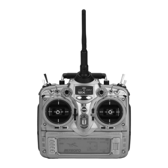
- Page 1 12-CHANNEL COMPUTER RADIO SYSTEM WITH SPEKTRUM 2.4GHz DSM TECHNOLOGY INSTRUCTION AND PROGRAMMING MANUAL...
-
Page 2: Table Of Contents
Table of Contents Using the Manual ............................I-11 Section 1: Transmitter and Receiver Features and Specifications ..............I-12 JR 12X Transmitter ...........................I-12 Features ..............................I-12 Specifications ............................I-12 Flash Memory ...............................I-12 Battery Alarm and Display ..........................I-12 JR R1221 Receiver............................I-13 Features ..............................I-13 Specifications ............................I-13 Charging ...............................I-14 Transmitter/Receiver ..........................I-14 JR Transmitter Charging ...........................I-14 Using the Included Charger ........................I-14... - Page 3 84: MODEL SELECT- (Copy Function) ......................A-6 To Select a Model Memory .........................A-7 Model Copy ..............................A-7 To Copy a Model to Another Internal Memory ...................A-7 81: Model Name ............................A-8 To Name a Model ............................A-8 28: Model Reset .............................A-9 To Reset a Model Memory .........................A-9 89: Type Select ............................A-10 To Select a Model Type ..........................A-10 85: Modulation - (12X MV System only) .....................A-11...
- Page 4 11: Servo Reversing ............................A-31 To Program Servo Reverse ........................A-31 12: Travel Adjust ............................A-31 To Program Travel Adjust Values ......................A-31 13: Dual Rate and Exponential ........................A-32 To Program Dual Rate and Exponential Values ..................A-32 Assigning Dual and Expo Rates to Flight Modes ..................A-32 To Assign D/R and Expo Values to Flight Modes ..................A-32 15: Sub Trim ..............................A-33 To Program Sub Trim Values ........................A-33...
- Page 5 Slave Channel ............................A-51 Point Names/Numbers ..........................A-51 Current Point Setting ..........................A-51 Vertical Line .............................A-51 Multi-Point Programmable Mixer ......................A-52 Graph ...............................A-52 Points That Can Be Added and Adjusted ....................A-52 Exponential ...............................A-52 Slave Channel Position ..........................A-52 Master Channel Position ..........................A-52 Switch Select ............................A-53 CLR Button ...............................A-53 LIST Button ..............................A-53 ENT Button ...............................A-53...
- Page 6 81: Model Name ............................H-8 To Name a Model ............................H-8 28: Model Reset .............................H-8 To Reset a Model Memory .........................H-8 89: Type Select ..............................H-9 To Select a Model Type ..........................H-9 85: Modulation - (12X MV System only) .....................H-10 To Program a Modulation Type ........................H-10 93: Frequency Select- (12X MV system only) ....................H-11 To Select a Frequency ..........................H-11 83: Trim System............................H-12...
- Page 7 16: Throttle Hold ............................H-31 Accessing the Throttle Hold Function .......................H-31 Stick Auto ..............................H-31 To Activate the Stick Auto Function ......................H-31 Hold Delay ..............................H-31 To Activate the Hold Delay........................H-31 18: Throttle Curves ............................H-32 Accessing the Throttle Curve Function .....................H-32 Exponential ...............................H-33 Trim (Mechanical Trim Lever) ........................H-33 Hovering Throttle .............................H-33 24: Servo Speed ............................H-34...
- Page 8 Points that Can Be Added and Adjusted ....................H-50 Exponential ...............................H-50 Slave Channel Position ..........................H-50 Master Channel Position ..........................H-51 Switch Select ............................H-51 CLR Button ...............................H-51 LIST Button ..............................H-51 ENT Button ...............................H-51 To Inhibit a Mixer (Turn it off entirely) .....................H-51 75: Monitor ..............................H-52 76: Mix Monitor ............................H-52 78: Trainer ..............................H-53 12X Used as Master (Instructor) ......................H-53...
- Page 9 97: Warning ..............................S-18 To Program a Warning ..........................S-18 98: Settings ..............................S-19 To Change Transmitter Settings .......................S-19 17: Device Select ............................S-19 Flight Modes.............................S-20 Activating and Assigning Primary Flight Modes ..................S-21 Activating and Assigning Additional Flight Modes ...................S-21 Aileron and Rudder Common Trims ......................S-21 Motor Function ............................S-22 Flap and AUX Functions ...........................S-22 Activating / Inhibiting Channels ........................S-22...
- Page 10 Master Channel - (Std. Prog Mixer) ......................S-38 Slave Channel - (Std. Prog Mixer) ......................S-39 Switch Position ............................S-39 Offset ................................S-39 Mix Values ..............................S-40 LR Button - (Std. Prog Mixer) ........................S-40 To Inhibit a Mix ............................S-40 Multi-Point Programmable Mixer ......................S-41 Master Channel ............................S-41 Slave Channel ............................S-41 Point Names/Numbers ..........................S-41 Current Point Setting ..........................S-42...
-
Page 11: Using The Manual
Using the Manual The 12X offers sophisticated programming features for three model types: airplanes, helicopters and sailplanes. This manual is divided into four sections. The first section, pages I-14 through I-27, includes common transmitter features and specifications plus overall operational information (i.e. charging batteries, binding, range checking and Frequently Asked Questions) sections that are common to all model types. -
Page 12: Section 1: Transmitter And Receiver Features And Specifications
• Resolution: 2048 Note: 12X MV also operates in PPM and S-PCM with included 72Mhz module. (A-PCM not supported in the US by Horizon Hobby - Japan market only) Flash Memory All preprogrammed data is protected by a flash memory that protects stored programming should the main transmitter battery ever fail or need replacing. -
Page 13: Jr R1221 Receiver
JR R1221 Receiver The R1221 receiver combines one internal with three remote a different RF environment creating a superior RF link in all receivers, offering superior path diversity. The radio system conditions. The JR R1221 allows an optional Flight Log data simultaneously transmits on two frequencies, creating up to recorder (JRPA145) to be used. -
Page 14: Charging
Charging Transmitter/Receiver Using the Included Charger Note: It is imperative that you fully charge both the The pilot lamps should always be on during the charging transmitter and the receiver battery packs prior to each operation. If not, check to make sure that both the transmitter flying session and that you check the condition of the and receiver are switched off. -
Page 15: Control Stick Tension Adjustment
Control Stick Tension Adjustment Stick tension adjustments are accessible through covers that are located on the back of the transmitter (see photo). Carefully pull back the cover or remove the grip to access the gimbals’ tension screws and then, using a small Phillips screwdriver, adjust each gimbal’s tension screw for the desired tension (counterclockwise to loosen stick tension;... -
Page 16: Installing The Receiver
Installing the Receiver Installing the JR R1221 Using double-sided foam tape (servo tape), mount the remote receiver(s) keeping the remote antenna(s) at least 2” away from the primary antenna. Ideally the antennas will be oriented The JR R1221 incorporates a single internal receiver and three perpendicular to each other;... -
Page 17: Binding
Binding Binding is necessary to program the receiver to the transmitter so that the receiver will only recognize that specific transmitter, ignoring signals from any other sources. If the receiver is not bound to the transmitter, the system will not operate. During binding, the servo’s failsafe positions are stored. -
Page 18: Modelmatch
ModelMatch The 12X features patented ModelMatch technology that prevents the operation of a model if the wrong model memory is selected. During binding the receiver actually learns and remembers the specific model memory (1 through 50) that the transmitter is currently programmed to. Later, if the incorrect model memory in the transmitter is selected and the receiver is turned on, the model simply won’t operate, preventing a possible crash. -
Page 19: Smartsafe
SmartSafe This type of fail-safe is especially ideal for most types of electric aircraft and is also recommended for most types of gas- and glow-powered airplanes and helicopters. Here’s how SmartSafe works. Receiver Power Only When the JR R1221 receiver only is turned on (no transmitter signal is present) the throttle has no signal output. -
Page 20: After Connection
After Connection When the transmitter is turned on and after the receiver Some modelers using powered planes prefer to use this failsafe connects to the transmitter, normal control of all channels system to program a slight turn and low throttle to prevent occurs. -
Page 21: Range Testing
Range Testing Before each flying session, and especially with a new model, it’s important to perform a range check. The 12X incorporates a range testing system which, when the bind button on the transmitter is pressed and held, reduces the output power, 90 feet (30 paces) allowing a range check. -
Page 22: Advanced Range Testing
Advanced Range Testing Plug a Flight Log (optional, JRPA145) into the data port in the After one minute release the bind button. A successful range receiver and turn on the system (Tx and Rx). check will have less that ten recorded frame losses. Scrolling the Flight Log through the Antenna fades (A, B, L, R) allows Advance the Flight Log until F- frame losses are displayed by you to evaluate the performance of each receiver. -
Page 23: Flight Log-Optional For Jr R1221 Receiver
Flight Log—Optional for JR R1221 Receiver The Flight Log is compatible with JR R1221 receivers. The Flight Log displays overall RF link performance as well as the individual internal and external receiver link data. Additionally it displays receiver voltage. After a flight and before turning off the receiver or transmitter, plug the Flight Log into the Data port on the JR R1221 receiver. -
Page 24: Receiver Power System Requirements
Receiver Power System Requirements With all radio installations it is vital that the onboard power While JR’s receiver’s minimum operational voltage is 3.5 system provides adequate power without interruption to the volts, it is highly recommended the system be tested per the receiver even when the system is fully loaded (servos at guidelines below to a minimum acceptable voltage of 4.8 maximum flight loads). -
Page 25: Tips On Using 2.4Ghz Systems
Tips On Using 2.4GHz Systems While your DSM equipped 2.4GHz system is intuitive to Q: I’ve heard that the DSM system is less tolerant of low operate, functioning nearly identically to 72MHz systems, voltage. Is that correct? following are a few common questions from customers: A: All DSM receivers have an operational voltage range of 3.5 Q: Which do I turn on first, the transmitter or the receiver? to 10 volts. - Page 26 The wrong model has been selected in the model memory (Model Match). The transmitter is near conductive material (Tx case, truck bed, etc.) and the reflected 2.4GHz energy is preventing the system from connecting (see #2 above). The bind button was unknowingly (or knowingly) depressed and the transmitter was turned on previously, causing the transmitter to no longer recognize the receiver.
-
Page 27: Airplane - Acro Mode
Airplane – Acro Mode The ACRO mode is intended for powered fixed-wing aircraft. • Aileron-To-Flap mixing It contains a host of advanced features that are designed to • Governor mixing assist the pilot in realizing the full potential of the aircraft. These •... -
Page 28: Transmitter Identification Acro
Transmitter Identification ACRO Antenna Gear Switch Handle Elevator D/R Mix Switch Flight Mode Switch Flap Switch AUX 2 Switch Rudder D/R Switch Left Trimmer/Trainer AUX 4 Knob AUX 5 Knob Switch Aileron D/R Switch Left Side Lever Right Side Lever Throttle/Rudder Stick Right Trimmer/Trainer Switch... - Page 29 AUX 6 Knob Rudder D/R Handle Throttle Spring Tension Cover AUX 7 Knob Elevator Spring Tension Cover Left Slider Right Slider Bind/Range Check Button Trainer/Transfer/PC Interface Jack Rudder Spring Tension Cover Aileron Spring Tension Cover Charge Jack Battery Door...
-
Page 30: System Mode
System Mode System mode contains the foundational programming that is normally only used when first setting up a model. System mode functions include: model select, model name, model reset, wing type, etc.—functions that are typically set once during setup and then are seldom changed or adjusted. Below, and throughout this section, the functions are in the order that they appear in the System Mode List. -
Page 31: Function Mode
Function Mode FUNCTION MODE contains programming functions that are used to complete the setup and then used to adjust and fine- tune how the model flies. Below, and throughout this section, the functions are in the order that they appear in the Function List. -
Page 32: System Mode
System Mode Programming a new model generally begins by accessing the SYSTEM Mode List. System Mode is where models are selected, the model type is chosen (airplane, helicopter or sailplane) and other high-level information is programmed for the model. It is also used to activate some of the more advanced programming features such as Flight Modes, Switch Assignments, Wing Types and Dual Control functions. -
Page 33: To Select A Model Memory
To Select a Model Memory 1. In the SYSTEM MODE, highlight and select Model SEL using the rolling Selector. 2. Use the rolling Selector to highlight MODEL then press the roller and select the desired model number to be used. 3. -
Page 34: 81: Model Name
81: Model Name The model name screen allows each model to be given up to a sixteen-digit name or number. This is convenient for identifying a model. The model’s name will appear on the main info screen. To Name a Model 1. -
Page 35: 28: Model Reset
28: Model Reset Model Reset is used to reset all programming to factory default settings. When setting up a new model it is important to reset all parameters to their default or factory settings before proceeding with any other programming. This is to ensure that there are no programming values or functions active from a previous model or programming session. -
Page 36: 89: Type Select
89: Type Select Type select allows the model type to be selected. Model types include HELI (helicopter), ACRO (airplane) and GLID (glider). Note: When changing model types, the programming information will be reset to the factory default setting, losing the previous settings. To Select a Model Type 1. -
Page 37: 85: Modulation - (12X Mv System Only
85: Modulation - (12X MV System only) Note: This function is only available on the 12X MV The 12X MV version radio system allows the RF module to be version and only when the TSM-72A 72MHz module is replaced allowing the system to operate on 72MHz or 2.4GHz. plugged in. -
Page 38: 93: Frequency Select- (12X Mv System Only
93: Frequency Select- (12X MV system only) Note: This function is only available on the 12X MV The 12X MV version radio system allows the RF module to be version and only when the TSM-72A 72MHz module is replaced allowing the system to operate on 72MHz or 2.4GHz. plugged in. -
Page 39: 83: Trim System
83: Trim System The Trim System function adjusts the sensitivity of the 12X trim When adjusting the digital trims (AILE, ELEV, RUDD), the total levers and the Flap and Aux trimmers (right and left trimmers). trim travel does not change – only the number of increments The standard digital trims are adjustable from 0–10 with 10 (beeps) changes, which makes for finer or coarser trim being the coarsest adjustment and 0 being trim off. -
Page 40: To Adjust The Trim Rates
To Adjust the Trim Rates: 1. Highlight and select TRIM SYS. in the SYSTEM MODE to Note: The Flap and AUX trims are adjustable from 0 to acquire the Trim System function. 200 and can be turned off or on by selecting On or Off. 2. -
Page 41: 91: Stick Position Switch
91: Stick Position Switch The Stick Position Switch function allows the throttle, aileron elevator or rudder stick positions to be preprogrammed to turn on/ off mixes, change throttle curves, change differential rates, start a timer and other functions. An example of this would be to have a smoke system that turns off below 25% throttle to prevent low throttle flameouts. -
Page 42: 92: Flight Mode Name
92: Flight Mode Name The Flight Mode Name program allows each flight mode to be custom named with up to six characters. On the main screen an abbreviated (short name of up to four characters) will be automatically displayed when that flight mode is selected. Examples for flight mode names may include 3DRATE, LAND, ROLLER, etc. -
Page 43: 86: Transfer
86: Transfer The TRANSFER function allows one 12X transmitter to transfer a Note: The sending and receiving transmitters must model memory for a specific model to another 12X transmitter. both be 12X’s or the PC Data Transfer device and a 12X. This function is also used to transfer a model memory to the Transfer is not possible with any other system. -
Page 44: Preparing The 12X To Send A Model Transfer
Preparing the 12X to Send a Model Transfer 1. With the other end of the trainer cord plugged into the sending 12X transmitter in SYSTEM List as described in step 1 above, highlight and select TRANSFER (code 86) in the SYSTEM Menu to obtain the Transfer display. 2. -
Page 45: 97: Warning
97: Warning The Warning function can be programmed to sound an alarm if • Flight Mode 0 • Flight Mode 1 a selected flight mode, switch positions or throttle stick position • Flight Mode 2 • Flight Mode 3 is in an inappropriate position when the transmitter is turned •... -
Page 46: 98: Settings
98: Settings The Settings program allows the screen backlight to be turned on/ off/ or placed in auto (sleep) mode. This function also allows the audible beeper to be turned on or off. These functions are defaulted to Backlight Auto and Silent Mode off. To Change Transmitter Settings 1. -
Page 47: 17: Device Select
17: Device Select Device Select is used to activate some of the more advanced • Flight Modes (5 in total) features of the 12X. The Device SEL function is used to activate/ • Throttle Hold inhibit the following: • Flap Trim •... -
Page 48: To Activate Flight Modes
To Activate Flight Modes 1. From SYSTEM Mode List, highlight and select DeviceSEL using the Selector. 2. Using the Selector, highlight and select INH next to FLIGHT MODE. When selected, 7 options appear: (Flight Mode SW, Rudder D/R SW, Flap SW, Elevator D/R SW, Aux 2 SW, Aileron D/R SW, or INH) Highlight and select the desired flight mode switch. -
Page 49: Throttle Hold
Throttle Hold The throttle hold function is normally used as a kill switch Note: Throttle hold is defaulted to the mix switch. for glow-powered airplanes or as a safety/ arming switch for electric-powered aircraft. It can also be used to preset a programmed throttle position. -
Page 50: Flap Trim
Flap Trim 1. The digital FLAP TRIM lever is located on the front right Ordinarily this switch should be turned OFF, even if the aircraft face of the transmitter and is accessed with your right has flaps or dual ailerons, The 12X provides other means of index finger. -
Page 51: Trim
Trim The Trim function can be toggled between COM (common) trim to change, such as when flaps are deployed by one of the and F.M. (Flight Mode) by pressing the Selector when COM Flight Modes causing the aircraft to have a pitch change. In this or F.M. -
Page 52: Switch Assignments
Switch Assignments The 12X provides the ability to change the standard default switch assignments for the GEAR, FLAP, AUX2, AUX3, AUX4, AUX5, AUX6, and AUX7 channels. Changing the switch assignments is a matter of preference. The standard switch assignments may be changed in the Devic.SEL function contained in the SYSTEM MODE. -
Page 53: 22: Wing Type
22: Wing Type Wing Types The Wing Type function provides for 4 different wing types DELTA is used with Delta wing aircraft (also referred to as (NORMAL, FLAPERON, DELTA and 4- Aileron). Elevon). With Delta wing type the Ailerons and elevator are mixed giving roll and pitch control for Delta wing airplanes. -
Page 54: Wing Type
Wing Type To Program a Wing Type 1. Highlight and select Wing Type in the System Mode List Note: If the ailerons are not going to actually be used using the roller. as flaps, inhibit the FLAP Switch and FLAP TRIM in the Devic.SEL function in the SYSTEM Menu. -
Page 55: V-Tail
V-Tail 1. If the aircraft has a V-tail configuration, highlight INH next to V-tail in the Wing TYPE function and press the roller until ACT appears. Plug the right Elevator servo into the Elevator channel (Ch3) and plug the left Elevator servo into the Rudder channel (Ch4). -
Page 56: Twin Engine
Twin Engine If the aircraft is equipped with twin engines, the Twin Engine feature (Twin E.) may be used for a 2nd throttle channel with an optional separate digital trim. 1. Highlight and select INH next to Mate under Twin ENGIN. 2. -
Page 57: 11: Servo Reversing
11: Servo Reversing The servo reverse screen allows the direction of each servo to be selected. To Program Servo Reverse 1. Highlight and select REV.SW in the FUNC.LIST to obtain the 2. Use the Selector to highlight and select those channels servo reversing display. -
Page 58: 13: Dual Rate And Exponential
13: Dual Rate and Exponential Three dual and exponential rates are available and are selectable Note: If extra flight modes are activated, up to 5 dual and via flight modes or selected switches. exponential rates are available. Dual and Expo rates are independently adjustable in each direction by moving the appropriate stick in the desired direction. -
Page 59: 15: Sub Trim
15: Sub Trim Use Sub Trims to fine-tune the output alignment of the servo arms. To Program Sub Trim Values 2. Highlight and select the channels where the sub trims must 1. Highlight and select Sub Trim in the FUNC.LIST to obtain be adjusted. -
Page 60: 18: Throttle Curves
18: Throttle Curves Programmable throttle curves allow the throttle response (stick If the Twin E. function has been activated in Wing Type (page position vs. throttle output) to be manipulated. This is useful to A-27 for twin-engine aircraft, independent throttle curves are optimize the throttle response for various maneuvers like torque available for each engine to help eliminate discrepancies in rpm rolls. -
Page 61: 24: Servo Speed
24: Servo Speed The 12X provides the ability to adjust the speed of servos on The servo speed function can be very useful for scale models each channel in each direction. The speed may be reduced with retractable landing gear and gear doors, since in many (servo slowed) from its normal speed but it cannot cause a instances the need for gear door sequencers can be eliminated. -
Page 62: 31: Snap Roll
31: Snap Roll The 12X has a Snap Roll system that can combine the Snap A Snap Roll stick switch position (Stick SW) can be Roll switch with Flight Modes to select a direction (Right/ programmed that will cause the respective control surface to Up, Right/Down, Left/Up, and Left/Down) and the amount of skew to the programmed snap roll position when the stick is deflection for Aileron, Elevator and Rudder. -
Page 63: 32: Differential
32: Differential The 12X Aileron Differential function reduces the travel of the The Aileron Differential function provides for 2 differential Aileron that deflects downward without affecting the Aileron settings that are switch or Flight Mode selectable – Pos0 and that travels upward and, therefore, can eliminate adverse yaw Pos1. -
Page 64: 33: Balance
33: Balance The 12X features a Balance function that allows the servo Note: Balance is available in the FUNC.LIST only if the outputs of dual channels to be adjusted throughout the range. FLAPERON, Delta or 4-Aileron is selected in the Wing This is useful when two servos are used to drive a single Type or if any of the dual functions (i.e. -
Page 65: 44: Gyro Sensor
44: Gyro Sensor The 12X features a Gyro Gain system that allows in-flight Note: In order for the GYRO System to appear in the selection of 3 gyro gain settings for up to two separate gyros FUNC.LIST, the AUX2 and/or the AUX3 channels must be or up to five gyro gain settings assigned to flight modes. -
Page 66: 45: Governer
45: Governer The 12X features a Governor program that can be activated in Note: Flight modes must be activated in Device Select to the Device Select screen. The Governor program is designed to access the governor screen. be used with most currently available Governor systems, and allows for independent rpm settings for each of the active flight modes. -
Page 67: 62: Aileron To Rudder
62: Aileron to Rudder The 12X features a preprogrammed Aileron-to-Rudder mix. This mix causes the Rudder to deflect when the Ailerons are moved. This is useful for some types of aircraft that have adverse yaw, (right aileron results in a left yaw). By programming aileron to rudder mix in the same direction the airplane will make coordinated turns using ailerons only. -
Page 68: 63: Elevator To Flap
63: Elevator to Flap The 12X features a preprogrammed Elevator-to-Flap mix. The mixer causes the Flaps (or Flaperons) to move when the Elevator is moved, resulting in tighter looping maneuvers, or to provide some Aileron reflex for some 3D maneuvers such as Harriers. -
Page 69: 64: Rudder To Aileron/Elevator Mix
64: Rudder to Aileron/Elevator Mix The 12X features a Rudder to aileron/ elevator mix that is used to eliminate roll and pitch coupling when rudder is applied. Two mixes are available and independent mix values can be assigned for each direction. Various switches and flight modes as well the throttle stick and other stick positions (SPS) can be used to select either of the mixes. -
Page 70: 66: Flap System
66: Flap System The 12X features a three-position Flap System with Elevator Because flaps generally causes a change in pitch (Elevator compensation, programmable Delay, and an Auto Land feature. trim), the Flap System provides for setting an Elevator deflection Its purpose is to allow the flaps to be programmed to three for each flap position. -
Page 71: Flap
Flap The FLAP values correspond with how far the flaps deflect when 2. With the Flap switch in the mid position, scroll to Mid in the NORM, Mid, and Land positions. Generally the NORM under FLAP on the display and select it. Adjust the desired position represents normal flying where the flaps are fully percentage to deflect the flaps the desired amount. -
Page 72: 51 Thru 58: Programmable Mixers
51 thru 58: Programmable Mixers Programmable mixers are programmed to cause a second extremely useful for programming proportional channel to be or slave channel to react as a result of providing input to operated via a trimmer or lever. Additionally programmable the primary or master channel or to cause a channel to be mixes can always be on, or turned off and on via a programmed controlled by moving a switch or lever. -
Page 73: Master Channel - (Std. Prog Mixer
Master Channel - (Std. Prog Mixer) The Master channel is the primary or controlling channel. The default for both the Master the Slave channel is THRO. The Master channel is selected by highlighting and selecting this parameter to obtain a list of channels and then selecting the Master channel from the list. -
Page 74: Slave Channel - (Std. Prog Mixer
Slave Channel - (Std. Prog Mixer) The Slave channel is the secondary receiving channel and will The Slave channel is selected by highlighting and selecting move according to the program mix in relation to the Master this parameter to obtain a list of channels and then selecting channel. -
Page 75: Offset
Offset Offset defines the position where the mixer changes directions. The Offset may be changed by highlighting and selecting The Offset is defaulted to center position or 0 and this is most Offset and adjusting either a positive (+) or negative (-) value. commonly used. -
Page 76: Clr Button - (Std. Prog Mixer
CLR Button - (Std. Prog Mixer) Note: Pressing the CLR button while a modifiable parameter is selected will reset the parameter to its default value. Pressing the CLR button when either the Master or Slave is highlighted Inhibits the entire mixer and it is no longer functional. -
Page 77: Slave Channel
Slave Channel This is the Slave channel that will move according to the program mix in relation to the Master channel. The Slave channel is selected by highlighting and selecting this parameter to obtain a list of channels and then selecting the Slave channel from the list. -
Page 78: Multi-Point Programmable Mixer
Multi-Point Programmable Mixer Graph The graph illustrates the mixing curve. The X-Axis (horizontal plane) represents Master channel movement. The Y-Axis (vertical plane) represents the Slave servo movement where the bottom 1/2 of the graph is one direction from neutral and the top portion of the graph is the other direction. -
Page 79: Switch Select
Switch Select There are numerous switches that can be used to switch To select a switch that will switch between the Pos0 and Pos1 between the Pos0 and Pos1. values, highlight and select the switch name and it will toggle between Pos0 and Pos1. -
Page 80: 67: Aileron-To-Flap Mix
67: Aileron-to-Flap Mix Aileron-to-Flap mix causes the flaps to move in unison with the ailerons. This function gives added roll response by mixing ailerons to flaps such that the entire trailing edge functions as an aileron. Note: This function is only available when Dual Flap is assigned in the Wing Type function. -
Page 81: 68: Pitch Curve
68: Pitch Curve The Pitch Curve is used to control variable pitch propellers. The Pitch function works nearly identically to a programmable curve mix, allowing up to 8 points to be stored and adjusted throughout the curve. Two curves are available (Pos0 and Pos1) and are selectable with various switches, flight modes, throttle position or Stick positions (SPS). -
Page 82: Vertical Line
Vertical Line The vertical line on the graph shows the current throttle channel position. When the throttle channel is deflected fully in one direction, the line is to the extreme left over Point-L, when it is at neutral it is in the center over Point-1 and when it is fully deflected in the other direction the cursor is at the extreme right of the graph over Point-H. -
Page 83: Switch Select
Switch Select There are numerous switches that can be used to switch To select a switch that will switch between the Pos0 and Pos1 between the Pos0 and Pos1. Note: if the upper and lower values, highlight and select the switch name and it will toggle settings for Pos0 or Pos1 are left at 0% the mixer can be turned between Pos0 and Pos1. -
Page 84: 75: Monitor
75: Monitor The Monitor screen displays each channel and shows the Flaperon is the wing type, the Monitor will display RAIL for movement of channels when sticks, levers and switches are right Aileron and LAIL for left Aileron instead of displaying moved. -
Page 85: 78: Trainer
78: Trainer The 12X features a programmable Trainer System that allows All Dual and Expo rates, Gear, and flap positions are controlled the instructor to transfer some or all of the primary flight control by the Master Tx. Only the Throttle, Aileron, Elevator and functions (Throttle, Aileron, Elevator and Rudder) to the student. -
Page 86: 87: Timer
87: Timer The 12X features a sophisticated Timer System with three timers. An integrated timer keeps track of total Tx-on time for the current selected model and integrated time is displayed on the Main display. Two other timers can be configured as Countdown timers or as Stopwatches. -
Page 87: 12X Helicopter Mode
12X Helicopter Mode Introduction The 12X Heli Mode programming is designed for model • Switch Assignability for channels and functions helicopters and includes 6 swashplate types making it • 50-model memory compatible with virtually every type of helicopter. The 12X •... -
Page 88: Heli Programming
Heli Programming Pilots that have previous experience programming JR radios of the manual is presented in the same order as the functions may feel confident programming the 12X without referring to appear in the transmitter beginning with the System Menu the manual. - Page 89 Handle Rudder D/R AUX 7 Knob AUX 6 Knob Left Lever Right Lever Throttle Spring Tension Cover Elevator Spring Tension Cover Bind/Range Check Button Trainer/transfer/PC Interface Jack Rudder Spring Tension Cover Aileron Spring Tension Cover Charge Jack Battery Door...
-
Page 90: System Mode
System Mode System mode contains the foundational programming that is normally only used when first setting up a helicopter. System mode functions include: model select, model name, model reset, Swashplate type etc.—functions that are typically set once during setup and then are seldom changed or adjusted. Below and throughout this section the functions are in the order that they appear in the System Mode List. -
Page 91: Function Mode
FUNCTION MODE Function Mode contains programming functions that are used to complete the setup and then used to adjust and fine-tune how the helicopter flies. Below and throughout this section the functions are in the order that they appear in the Function List. To Enter Function Mode Press the LIST button after the transmitter is powered-up to obtain the Function List. -
Page 92: System Mode
System Mode Programming a new model generally begins by accessing the SYSTEM Mode List. System Mode is where models are selected, the model type is chosen (airplane, helicopter or sailplane) and other high-level information is programmed. It is also used to activate some of the more advanced programming features such as Flight Modes, Switch Assignments and Swashplate Types. -
Page 93: Model Copy
Model Copy Making a backup copy of the model memory protects against losing the original program and also allows one to experiment with the original program, knowing that the original settings can be restored by copying the backup copy back to the original model memory. -
Page 94: 81: Model Name
81: Model Name The model name screen allows each model to be given up to a sixteen digit name or number. This is convenient for identifying a model. The model’s name will appear on the main info screen. To Name a Model 1. -
Page 95: 89: Type Select
89: Type Select Type select allows the model type to be selected. Model types include HELI (helicopter), ACRO (airplane) and GLID (glider). Note: When changing model types, the programming information will be reset to the factory default setting losing the previous settings. To Select a Model Type 1. -
Page 96: 85: Modulation - (12X Mv System Only
85: Modulation - (12X MV System only) Note: This function is only available on the 12X MV The 12X MV version radio system allows the RF module to be version and only when the TSM-72A 72MHz module is replaced allowing the system to operate on 72MHz or 2.4GHz. plugged in. -
Page 97: 93: Frequency Select- (12X Mv System Only
93: Frequency Select- (12X MV system only) Note: This function is only available on the 12X MV The 12X MV version radio system allows the RF module to be version and only when the TSM-72A 72MHz module is replaced allowing the system to operate on 72MHz or 2.4GHz. plugged in. -
Page 98: 83: Trim System
83: Trim System The Trim System function adjusts the sensitivity of the 12X When adjusting the digital trims (AILE, ELEV, RUDD), the total trims, hovering throttle and hovering pitch trim levers and the trim travel does not change – only the number of increments high pitch lever. -
Page 99: To Adjust The Trim Rates
To Adjust the Trim Rates 1. Highlight and select TRIM SYS. in the SYSTEM MODE to acquire the Trim System function. 2. Highlight and select the trim that is to be changed and use the Selector to set a value of 1–10 (1 = finest, 10 = coarsest;... -
Page 100: 91: Stick Position Switch
91: Stick Position Switch The Stick Position Switch function allows the throttle, aileron elevator or rudder stick positions to be preprogrammed to turn on/off mixes or the timer. Four stick position programs are available and one or more can be assigned to various mixes or functions. -
Page 101: 92: Flight Mode Name
92: Flight Mode Name The Flight Mode Name program allows each flight mode to be custom named with up to six characters. On the main screen an abbreviated name of up to four characters will be automatically displayed when that flight mode is selected. Examples for flight mode names may include START, 3D, STUNT2, HOVER, etc. -
Page 102: 86: Transfer
86: Transfer The TRANSFER function allows one 12X transmitter to transfer a Note: The sending and receiving transmitters must both model memory for a specific model to another 12X transmitter. be 12X’s, or the PC Data Transfer device and a 12X. This function is also used to transfer a model memory to the Transfer is not possible with any other system. -
Page 103: Preparing The 12X To Send A Model Transfer
Preparing the 12X to Send a Model Transfer 1. With the other end of the trainer cord plugged into the sending 12X transmitter in SYSTEM List as described in step 1 above, highlight and select TRANSFER (code 86) in the SYSTEM Menu to obtain the Transfer display. 3. -
Page 104: 97: Warning
97: Warning The Warning function can be programmed to sound an alarm if • Flight Mode Normal a selected flight mode, switch positions or throttle stick position • Flight Mode 1 is in an inappropriate position when the transmitter is turned •... -
Page 105: 98: Settings
98: Settings The Settings program allows the screen backlight to be turned on/off or placed in auto (sleep) mode. This function also allows the audible beeper to be turned on or off. These functions are defaulted to Backlight Auto and Silent Mode off. To Change Transmitter Settings 1. -
Page 106: 17: Device Select
17: Device Select Device Select is used to activate some of the more advanced • Assign Switch, Lever and Knob assignments features of the 12X. The Device SEL function is used to activate/ • Activate/inhibit switches/channels inhibit or assign the following: •... -
Page 107: Activating Extra Flight Modes 3 And 4
Activating Extra Flight Modes 3 and 4 The 12X offers up to 6 separate flight modes. The system is factory defaulted to offer 4 flight modes (N, 1, 2, Hold) plus there are 2 additional flight modes, numbered 3 and 4 that can be activated through the Device Select function. -
Page 108: To Assign The Throttle Hold To A Switch
To Assign the Throttle Hold to a Switch 1. In device select highlight and select THRO Hold. The screen will appear that allows ten different switches to be assigned as the Throttle Hold switch. 2. Using the roller, select the desired switch to activate Throttle Hold. -
Page 109: Hover Analog
Hover Analog The Hover Analog function allows the pilot to select either the digital trim levers (HVTH and HVPT) or the Aux 4 and Aux 5 knobs to be used as hovering pitch and hovering throttle. The Hover Analog parameter can be toggled back and forth between ACT and INH by pressing the Rolling Selector when ACT or INH is highlighted. -
Page 110: To Change One Or More Switch Assignments
To Change One or More Switch Assignments 1. In the Device SEL function, use the Selector to highlight and select GEAR, AUX2 thru AUX7 channels. 2. Once a channel is selected, a list of available replacement switches is displayed. Highlight and select the desired switch with the Selector. -
Page 111: Deactivating Channels
Deactivating Channels The 12X provides the ability to inhibit a number of channels. This is useful when auxiliary channels are used for mixing. In this instance, the switch will no longer operate the channels allowing them to be used as slave channels. Also the deactivated channels will assume a centered (1.50ms) position needed for mixing. -
Page 112: 34: Swashplate Type
34: Swashplate Type The Swashplate Type function enables the 12X to operate six The Swashplate options are: different types of swashplate control systems. • 1 Servo NORM standard mechanical mixing type • 2 Servo/180° • 3 Servo/120° CCPM (most popular) •... -
Page 113: Function Mode
Function Mode The Function Mode contains programming that is used to and Throttle Curves, Swashplate Mixes, Programmable Mixes, complete the setup and then to adjust the helicopter’s flight Gyro Programming, Governor Programming, Trainer and Timer characteristics. Functions include Servo Reversing, Travel Functions, etc. -
Page 114: 12: Travel Adjust
12: Travel Adjust Travel Adjust allows the independent adjustment of servo travel for each direction of servo travel. To Program Travel Adjust Values 1. Highlight and select TRVL ADJ. in the FUNC.LIST to obtain the Travel Adjust display. 2. Use the Selector to highlight and select each channel and adjust the travel in each direction by rotating the Selector. -
Page 115: 13: Dual Rate And Exponential
13: Dual Rate and Exponential Up to six dual and exponential rates are available and are Linear curve types are available that allow the tailoring of the selectable via flight modes (up to 6) or dual rate switches output curve. Dual and Expo rates are independently adjustable (up to 3). -
Page 116: Auto Function
AUTO Function 5. The AUTO function automatically selects Dual Rate and Expo setting in each flight mode. If the AUTO function is desired highlight the desired switch under AUTO and select SW for dual rate switch or the desired D/R position to automatically activate that selection when the corresponding flight mode is selected. -
Page 117: 16: Throttle Hold
16: Throttle Hold The Throttle Hold function is designed to hold the throttle Throttle Hold switch is defaulted to the top right-rear corner output position in a specific position when the throttle hold of the transmitter, however, a different switch can be selected switch is activated but still allow full pitch and cyclic control. -
Page 118: 18: Throttle Curves
18: Throttle Curves The 12X offers up to five (5) separate throttle curves with up to Positions 1 and 2 (Stunt 1 and Stunt 2) are typically used for eight adjustable points per curve. This function allows you to forward flight and 3D maneuvers. Optional flight modes 3 and 4 customize the throttle curve to maximize engine performance are also designed for use with aerobatic maneuvers and forward at any particular pitch setting. -
Page 119: Exponential
Exponential The Exponential function blends the Curve between the points on the graph to provide a smooth response. The default value is OFF. To turn it on and smooth the mixing curve, highlight and select OFF and it will toggle to ON. An Expo function can be selected independently for each flight mode. -
Page 120: 24: Servo Speed
24: Servo Speed The 12X provides the ability to adjust the speed of servos for each channel in each direction. The speed may be reduced (servo slowed) from its normal speed but it cannot cause a servo to move faster than its rated specifications. Each servo can have 2 sets of speeds in each direction that are Flight Mode or switch selectable. -
Page 121: 42: Mix To Throttle
42: Mix to Throttle The 12X Cyclic-to-Throttle function is designed to add throttle The most common use for Cyclic-to-Throttle mixing is for to prevent main rotor rpm decay resulting from load changes Stunt Modes, allowing the main rotor rpm to remain consistent placed upon the engine when an Aileron, Elevator or Rudder throughout aerobatic and 3D maneuvers. -
Page 122: 44: Gyro Sensor
44: Gyro Sensor The 12X offers three different types of Gyro Gain Sensitivity Note: To access the gyro function, the Gear, Aux1 or Aux Adjustments: manual, flight mode or automatic. This feature 2 channels must be programmed to GYR in device select gives the user the choice of selecting gyro sensitivity through code 17 and the gyro gain lead must be plugged into this the rudder, aileron or elevator dual rate switches (manual),... -
Page 123: 45: Governor
45: Governor The 12X Governor function is designed to be used with most The Governor programs operational channel can be assigned to currently available Governors. The Governor function allows the Gear, Aux1 or Aux2 channels in the Device Select screen. rpm values to be set for each of the Active Flight modes, and Note: To access the Governor function, the Gear, Aux1 or will automatically change the Governor rpm values when the... -
Page 124: 47: Tail Curves- (Use Only With Non-Heading Hold Gyros
47: Tail Curves- (Use Only with Non-Heading Hold Gyros) The 12X offers up to five (5) separate tail curves with up to The flight mode switch offers three selectable positions: eight adjustable points per curve. This function allows you to •... -
Page 125: 61: Dual Pitch
61: Dual Pitch The Dual Pitch function is designed for use with mechanical Note: This function is only available if the 1 servo NORM mix helicopters (non-CCPM) where two servos are used is selected in swashplate type and if the PIT function is to control the pitch function. -
Page 126: 65: Swashplate Mix
65: Swashplate Mix The Swashplate Mix screen has several important functions. These functions include: Aileron, Elevator and Pitch Authority This function independently adjusts the maximum travel of the servos that work in unison for aileron, elevator and pitch control. If the aileron value is increased, the servos that control aileron only (the pitch and aileron servos) will increase travel when the ailerons are deflected and won’t affect pitch or elevator travel. -
Page 127: Elevator-To-Pitch Canceller
Elevator-to-Pitch Canceller This function compensates for the different distance/ time traveled by the pitch, aileron and elevator servos with elevator inputs. Note: The swashplate type must be selected in System Mode code 34 Swash TYP (see Page H-26). Accessing the Swashplate Mixing Function 1. -
Page 128: 68: Pitch Curves
68: Pitch Curves The 12X offers up to five (5) separate pitch curves with up to Positions 1 and 2 (Stunt 1 and Stunt 2) are typically used for eight adjustable points per curve. This function allows you to forward flight and 3D maneuvers. Optional flight modes 3 and 4 customize each pitch curve at any particular pitch setting. -
Page 129: Exponential
Exponential The Exponential function blends the Curve between the points on the graph to provide a smooth response. The default value is OFF. To turn it on and smooth the pitch curve, highlight and select OFF and it will toggle to ON. Hovering Pitch Hovering Pitch increases or decreases the servo output via the trimmer or knob for the selected points set for the pitch curve. -
Page 130: 51 Thru 58: Programmable Mixers
51 thru 58: Programmable Mixers Programmable mixers are programmed to cause a second Mixes are fully programmable, allowing any of the 12 channels or slave channel to react as a result of providing input to to be master, slave or both (a channel can be mixed to itself). the primary or master channel or to cause a channel to be Trimmers and levers can also be used as a master and are controlled by moving a switch or lever. -
Page 131: Master Channel - (Std. Prog Mixer
Master Channel - (Std. Prog Mixer) The master channel is the primary or controlling channel. The default for both the master and the slave channels is THRO. The master channel is selected by highlighting and selecting this parameter to obtain a list of channels and then selecting the Master channel from the list. -
Page 132: Slave Channel - (Std. Prog Mixer
Slave Channel - (Std. Prog Mixer) The slave channel is the secondary receiving channel and The slave channel is selected by highlighting and selecting will move according to the program mix in relation to the this parameter to obtain a list of channels and then selecting master channel. -
Page 133: Offset
Offset Offset defines the position where the mixer changes directions. The offset may be changed by highlighting and selecting The Offset is defaulted to center position or 0 and this is most Offset and adjusting either a positive (+) or negative (-) value. commonly used. -
Page 134: Clr Button - (Std. Prog Mixer
CLR Button - (Std. Prog Mixer) Note: Pressing the CLR button while a modifiable parameter is selected will reset the parameter to its default value. Pressing the CLR button when either the master or slave is highlighted inhibits the entire mixer and it is no longer functional. -
Page 135: Master Channel
Master Channel The master channel is the primary channel, lever or trim lever. designated by a “#” (pound sign) in front of the name - #FLP, The master channel is selected by highlighting and selecting #AIL, #ELE and #RUD. When one of these channels is selected this parameter to obtain a list of channels and then selecting the as the master, all D/R, EXP and Curve settings associated with master channel from the list. -
Page 136: Vertical Line
Vertical Line The vertical line on the graph shows the current master channel position. When the master channel is deflected fully in one direction, the line is to the extreme left over Point-L. When it is at neutral, it is in the center over Point-1 and when it is fully deflected in the other direction, the cursor is at the extreme right of the graph over Point-H. -
Page 137: Master Channel Position
Master Channel Position The master channel position is shown on the bottom line of the display next to IN and is expressed in values from 0 to 100 with 50 being the center or neutral position. It represents the present master channel position. -
Page 138: 75: Monitor
75: Monitor The Monitor screen displays each channel and shows the Flaperon is the wing type, the Monitor will display RAIL for movement of channels when sticks, levers and switches are right Aileron and LAIL for left Aileron instead of displaying moved. -
Page 139: 78: Trainer
78: Trainer The 12X features a programmable Trainer System that allows All Dual and Expo rates, Gear and flap positions are controlled the instructor to transfer some or all of the primary flight control by the master transmitter. Only the Throttle, Aileron, Elevator functions (Throttle, Aileron, Elevator and Rudder) to the student. -
Page 140: 87: Timer
87: Timer The 12X features a sophisticated timer system with three timers. on the main display when active and can be started and stopped An integrated timer keeps track of total transmitter-on time for via various switches. In addition an interval function can be the current selected model and integrated time is displayed programmed such that alarm will sound at preprogrammed on the main display. -
Page 141: 12X Sailplane Mode
12X Sailplane Mode Introduction The 12X GLID programming is optimized for multi-function • Triple Rates/Exponentials (up to 5 Rates/EXPOs for Aileron, sailplanes. The software was developed by some of the world’s Elevator and Rudder in flight modes) leading sailplane pilots, offering the highest level of versatility •... -
Page 142: Transmitter Identification- Sailplane
Transmitter Identification- Sailplane Antenna Handle Gear Switch Elevator D/R Switch Mix Switch Flap/Mix Switch Rudder D/R Switch Flight Mode Switch Aux 2 Switch AUX 5 Knob AUX 4 Knob Left Side Lever Aileron D/R Switch Right Trimmer Right Side Left Trimmer Lever Aileron/Elevator Stick Throttle/Rudder Stick... - Page 143 Handle Rudder D/R AUX 7 Knob AUX 6 Knob Left Lever Right Lever Throttle Spring Tension Cover Elevator Spring Tension Cover Bind/Range Check Button Rudder Spring Tension Cover Aileron Spring Tension Cover Trainer/Transfer/PC Interface Jack Battery Door Charge Jack...
-
Page 144: Programming A Sailplane
Programming a Sailplane The following section contains in-depth details regarding each of the available programming functions. If you’re just getting started, you’ll likely find it easier (and we recommend) using the Applications Guide included separately with your 12X system. This step-by-step guide leads you through a typical 6-servo sailplane giving the key strokes necessary to set up a sailplane, including flight modes, crow and side lever camber adjustments. -
Page 145: Function Mode
Function Mode Function Mode contains programming functions that are used in each flight mode. Below and throughout this section the to complete the setup and then used to adjust the parameters functions are in the order that they appear in the Function List. To Enter Function Mode Press the LIST button after the transmitter is powered-up to 63: ELEV-FLAP... -
Page 146: 84: Model Select- (Copy Function
84: Model Select- (Copy Function) Model Select allows the programming parameters for up to 50 Note: When setting up a new model it is recommended different models to be stored and selected in up to 50 individual that an unused model memory is selected. If a current model memories. -
Page 147: Model Copy
Model Copy Making a backup copy of the model memory protects against can be restored by copying the backup copy back to the original losing the original program and also allows one to experiment model memory. with the original program, knowing that the original settings To Copy a Model to Another Internal Memory 1. -
Page 148: 81: Model Name
81: Model Name The Model Name screen allows each model to be given up to a sixteen-digit name or number. This is convenient for identifying a model. The model’s name will appear on the main info screen. To Name a Model 1. -
Page 149: 28: Model Reset
28: Model Reset Model Reset is used to reset all programming to factory default proceeding with any other programming. This is to ensure that settings. When setting up a new model, it is important to there are no programming values or functions active from a reset all parameters to their default or factory settings before previous model or programming session. -
Page 150: 85: Modulation - (12X Mv System Only
85: Modulation - (12X MV System only) Note: This function is only available on the 12X MV The 12X MV version radio system allows the RF module to be version and only when the TSM-72A 72MHz module is replaced allowing the system to operate on 72MHz or 2.4GHz. plugged in. -
Page 151: 93: Frequency Select- (12X Mv System Only
93: Frequency Select- (12X MV system only) Note: This function is only available on the 12X MV The 12X MV version radio system allows the RF module to be version and only when the TSM-72A 72MHz module is replaced allowing the system to operate on 72MHz or 2.4GHz. plugged in. -
Page 152: 83: Trim System
83: Trim System The Trim System function adjusts the sensitivity of the spoiler, When adjusting the digital trims (AILE, ELEV, RUDD), the total aileron, elevator and rudder trims, plus the Flap trim and trim travel does not change – only the number of increments Flaperon trim levers. -
Page 153: To Adjust The Trim Rates
To Adjust the Trim Rates 1. Highlight and select TRIM SYS. in the SYSTEM menu to acquire the Trim System function. 2. Highlight and select the trim that is to be changed and use the Selector to set a value of 1–10 (1 = finest, 10 = coarsest. -
Page 154: 91: Stick Position Switch
91: Stick Position Switch The Stick Position Switch function allows the throttle, aileron elevator or rudder stick positions to be preprogrammed to turn on/ off mixes or the timer. Four stick position programs are available and one or more can be assigned to various mixes or functions. -
Page 155: 92: Flight Mode Name
92: Flight Mode Name The Flight Mode Name program allows each flight mode to be custom named with up to six characters. On the main screen an abbreviated (short name of up to four characters) will be automatically displayed when that flight mode is selected. Pre- programmed names for flight modes include Cruise, Speed, Thermal, Launch and Land, but these can be changed to any preference. -
Page 156: 86: Transfer
86: Transfer The TRANSFER function allows one 12X transmitter to transfer a Note: The sending and receiving transmitters must both model memory for a specific model to another 12X transmitter. be 12X’s, or the PC Data Transfer device and a 12X. This function is also used to transfer a model memory to the Transfer is not possible with any other system. -
Page 157: Preparing The 12X To Send A Model Transfer
Preparing the 12X to Send a Model Transfer 1. With the other end of the trainer cord plugged into the sending 12X transmitter in SYSTEM List as described in step 1. above, highlight and select TRANSFER (code 86) in the SYSTEM Menu to obtain the Transfer display. 2. -
Page 158: 97: Warning
97: Warning The Warning function can be programmed to sound an alarm if • Flight Mode Cruise a selected flight mode, switch position or spoiler stick position • Flight Mode Speed is in an inappropriate position when the transmitter is turned •... -
Page 159: 98: Settings
98: Settings The Settings program allows the screen backlight to be turned on/ off or placed in auto (sleep) mode. This function also allows the audible beeper to be turned on or off. Theses functions are defaulted to Backlight Auto and Silent mode off. To Change Transmitter Settings 1. - Page 160 Flight Modes A Flight Mode represents an aircraft configuration (camber Most of the functions found in the 12X that are switch position, trim positions, Dual Rate/Expo settings, program selectable, including Flaperon Mix, Servo Speed, Camber mixes, aileron differential value, etc.) that is programmed to system, Differential, Aileron to rudder mix, Elevator to flap mix, optimize the aircraft for a particular task.
-
Page 161: Activating And Assigning Primary Flight Modes
Activating and Assigning Primary Flight Modes In the factory default setting, all flight modes are inhibited. To activate the launch, cruise and land mode, rotate the Selector Flight modes are activated and assigned to the desired switch until LAUN is highlighted and then press the Selector. The position using the SPEED and LAUN functions in the Device following screen will appear: Device select w/ Launch screen. -
Page 162: Motor Function
Motor Function The motor function can be assigned to operate from several different switches, buttons or the Spoiler stick. In Device Select, highlight MOTO SW and press the Selector to access the available switches that can be programmed to operate the motor. -
Page 163: 22: Wing Type
22: Wing Type This Wing Type function is used to establish the programming Note: In order to activate any of the Dual Mate functions for wing and tail types. The Wing Type program allows the (dual elevator, rudder or flaps), channels must be inhibited activation of V-tail, Tip ailerons, dual elevators, dual rudders, in 17. -
Page 164: 11: Servo Reversing
11: Servo Reversing The servo reverse screen allows the direction of each servo to be selected. To Program Servo Reverse 1. Highlight and select REV.SW in the FUNC.LIST to obtain the servo reversing display. 2. Use the Selector to highlight and select those channels that need to be reversed. -
Page 165: 13: Dual Rate And Exponential
13: Dual Rate and Exponential Up to five dual and exponential rates are available and are (variable trace ratio), Linear/ Exponential and Exponential/ selectable via flight modes (up to 5) or Dual rate switches Linear curve types are available to allow the tailoring of the (up to 3). -
Page 166: 15: Sub Trim
15: Sub Trim Use Sub Trims to fine-tune the output alignment of the servo arms. To Program Sub Trim Values 1. Highlight and select Sub Trim in the FUNC.LIST to obtain 2. Highlight and select the channels where the sub trims must be adjusted. -
Page 167: 21: Flaperon Mix
21: Flaperon Mix Flaperon Mix Combines four mixes in one screen. Mixes include Flap-to-Flaperon mix, Flap-to-Elevator mix, Aileron-to- Flap mix, and Aileron-to-Tip aileron mix if the tip ailerons are activated in the wing type function. The flap lever-offset position is programmable allowing pilots to choose the neutral position. The flap functions can be programmed to one of many different levers or switches in the Device Select screen. -
Page 168: 24: Servo Speed
24: Servo Speed The 12X provides the ability to adjust the speed of servos for each channel in each direction. The speed may be reduced (servo slowed) from its normal speed but it cannot cause a servo to move faster than its rated specifications. Each servo can have 2 sets of speeds in each direction that are Flight Mode or switch selectable. -
Page 169: 25: Camber System
25: Camber System The Camber system allows preset camber adjustments for each to-Flaperon mix, Flap-to-Elevator mix, Aileron-to-Flap mix, programmed flight mode for the right and left ailerons, the right and Aileron-to-Tip aileron mix if the tip ailerons are activated and left flaps, and if activated the right and left tip ailerons. The in the wing type function. -
Page 170: 32: Differential
32: Differential The Aileron Differential function provides for up to 5 Differential The 12X Aileron Differential function reduces the travel of the and Brake Differential settings that are Flight Mode selectable. Aileron that deflects downward without affecting the Aileron When flight modes are activated in Device Select (see page that travels upward, eliminating adverse yaw effects and S-19), the differential screen displays an Aileron Differential improving coordinated turns. -
Page 171: 33: Balance
33: Balance The 12X features a Balance function that allows the servo to linkage geometry inaccuracies. The Balance function allows outputs of dual channels to be adjusted throughout the range. the servo output of the master servo to be adjusted at 7 points This is useful when two servos are used to drive a single throughout the range, compensating for any linkage geometry surface (i.e. -
Page 172: 44: Gyro Sensor
44: Gyro Sensor The 12X features a Gyro Gain system that allows for the 5) must be programmed to GYR in device select code 17 and individual in-flight selection of gain setting for each active flight the gyro gain lead must be plugged into the Moto (channel 5) mode. -
Page 173: 62: Aileron-To-Rudder Mix
62: Aileron-to-Rudder Mix Aileron-to-Rudder mix causes the rudder to move in unison with the ailerons. It is utilized to reduce adverse yaw and to improve the turning/ handling characteristics. Aileron-to-Rudder mix values can be independently adjusted right and left for each of the 5 flight modes. -
Page 174: 63: Elevator-To-Flap Mix
63: Elevator-to-Flap Mix Elevator-to-Flap mix is normally used to give several degrees of down flap when up elevator is applied. This gives more pitch authority than would elevator alone, and is commonly used for slope racers to improve high-speed turns and in thermal sailplanes to allow increased maneuverability for tight thermal turns. -
Page 175: 69: Flap Rate
69: Flap Rate The Flap Rate function adjusts the up and down flap travel when using the Flap Lever (default) or which ever lever or switch is selected to operate the flaps in Device Select Code 17. Each flight mode that is activated in Device Select code 17. will be displayed with a up and down value in the Flap Rate screen. -
Page 176: 71: Brake System
71: Brake System The Brake System is the landing program that mixes the spoilers, flaperons, flaps, and tip ailerons (if equipped) and elevator to the spoiler (throttle) stick. Two values are available, Pos0 and Pos1; each can be assigned to several different switches or flight modes. -
Page 177: 51 Thru 58: Programmable Mixers
51 thru 58: Programmable Mixers Programmable mixers are programmed to cause a second The primary channel is called the Master channel, while the or slave channel to react as a result of providing input to channel that reacts to the Master is called the Slave channel. the primary or master channel or to cause a channel to be Mixes are fully programmable, allowing any of the 12 channels controlled by moving a switch or lever. -
Page 178: Master Channel - (Std. Prog Mixer
Master Channel - (Std. Prog Mixer) The Master channel is the primary or controlling channel. The default for both the Master and the Slave channel is THRO. The Master channel is selected by highlighting and selecting this parameter to obtain a list of channels and then selecting the Master channel from the list. -
Page 179: Slave Channel - (Std. Prog Mixer
Slave Channel - (Std. Prog Mixer) The Slave channel is the secondary receiving channel and will The Slave channel is selected by highlighting and selecting move according to the program mix in relation to the Master this parameter to obtain a list of channels and then selecting channel. -
Page 180: Mix Values
Mix Values Each standard Programmable mixer can have two sets of mixing To enter Pos0 values, highlight and select Pos0, move the values - Pos0 and Pos1. Each set can have 2 percentages which Master channel control (stick, lever or switch) in one direction control movement of the Slave when the Master is moved in and set the percentage and then move the Master channel each direction. -
Page 181: Multi-Point Programmable Mixer
Multi-Point Programmable Mixer There are 5 Multi-Point Programmable Mixers in the 12x, Prog. to define the position of the Slave channel relative to the Master Mix4 through Prog.Mix8. They differ from the standard mixes in channel at up to 8 selectable points. As the Master reaches each that they allow non-linear mix response from the Master to the point, the Slave response position can be defined independent Slave. -
Page 182: Current Point Setting
Current Point Setting This list shows the setting for each of the 8 adjustable points The value for a point can be changed by highlighting and (Point-L, 1, 2, 3, 4, 5, 6, 7, H). The value of each point selecting the Point Name to the left of the point value and then determines where the point is positioned vertically on the graph, dialing-in the desired value. -
Page 183: Slave Channel Position
Slave Channel Position The Slave servo position next to OUT at the bottom left of the display is expressed in values from -100 to +100, with 0 being neutral or center. It represents the servo travel that corresponds to the present Master channel position. Master Channel Position The Master channel position is shown on the bottom line of the display next to IN and is expressed in values from 0 to 100 with... -
Page 184: 75: Monitor
75: Monitor The Monitor screen displays each channel and shows the Flaperon is the wing type, the Monitor will display RAIL for movement of channels when sticks, levers and switches are right Aileron and LAIL for left Aileron instead of displaying moved. -
Page 185: 78: Trainer
78: Trainer The 12X features a programmable Trainer System that allows All Dual and Expo rates, Gear, and flap positions are controlled the instructor to transfer some or all of the primary flight control by the Master Tx. Only the Throttle, Aileron, Elevator and functions (Throttle, Aileron, Elevator and Rudder) to the student. -
Page 186: 87: Timer
87: Timer The 12X features a sophisticated Timer System with three timers. An integrated timer keeps track of total Tx-on time for the current selected model and integrated time is displayed on the Main display. Two other timers can be configured as Countdown timers or as a Stopwatch. -
Page 187: General Information
General Information FCC Information Servo Precautions • Do not lubricate servo gears or motors. This device complies with part 15 of the FCC rules. Operation • Do not overload retract servos during retracted or extended is subject to the following two conditions: (1) This device may conditions.Make sure they are able to travel their full not cause harmful interference, and (2) this device must accept deflection. -
Page 188: Safety Do's And Don'ts For Pilots
Safety Do’s and Don’ts for Pilots • Do not fly during adverse weather conditions. Poor visibility can cause disorientation and loss of control of your aircraft. • Ensure that your batteries have been properly charged prior Strong winds can cause similar problems. to your initial flight. -
Page 189: Warranty Information
Warranty Information Three Year Warranty Period Damage Limits Exclusive Warranty- Horizon Hobby, Inc., (Horizon) warranties HORIZON SHALL NOT BE LIABLE FOR SPECIAL, INDIRECT that the Products purchased (the “Product”) will be free from OR CONSEQUENTIAL DAMAGES, LOSS OF PROFITS defects in materials and workmanship for a period of 3 years OR PRODUCTION OR COMMERCIAL LOSS IN ANY WAY from the date of purchase by the Purchaser. -
Page 190: Inspection Or Repairs
Champaign, Illinois 61822 Provided warranty conditions have been met, your Product will be repaired or replaced free of charge. Repair or replacement decisions are at the sole discretion of Horizon Hobby. Horizon Hobby UK Units 1-4, Ployters Road Staple Tye - Southern Way... - Page 192 © 2008 Horizon Hobby, Inc. 4105 Fieldstone Road Champaign, IL 61822 (877) 504.0233 www.horizonhobby.com 13042...
Need help?
Do you have a question about the JR DSM 12x and is the answer not in the manual?
Questions and answers
I have a JR/DSM 12x24 that will not come on!! Can you repair?? I don’t want to lose my programs!!