Table of Contents
Advertisement
871112
Updated 5/24
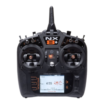
NX8+
8-Channel 2.4GHz
DSMX
Aircraft System
®
Instruction Manual
Bedienungsanleitung
Manuel d'utilisation
Manuale di Istruzioni
Scan the QR code and select the Support tab on
the product page for the most up-to-date manual
Scannen Sie den QR-Code und wählen Sie auf der
Produktseite die Registerkarte „Support", um die
aktuellsten Informationen zu Handbücher.
Scannez le code QR et sélectionnez l'onglet Support
sur la page du produit pour obtenir les informations
les plus récentes sur le manuel.
Scannerizzare il codice QR e selezionare la
scheda Supporto dalla pagina del prodotto per le
informazioni manuali più aggiornate.
SPMR8210
information.
Advertisement
Table of Contents

Related Manuals for Horizon Hobby Spektrum NX8+


Summary of Contents for Horizon Hobby Spektrum NX8+
- Page 1 NX8+ 8-Channel 2.4GHz DSMX Aircraft System ® Instruction Manual Bedienungsanleitung Manuel d’utilisation Manuale di Istruzioni SPMR8210 Scan the QR code and select the Support tab on the product page for the most up-to-date manual information. Scannen Sie den QR-Code und wählen Sie auf der Produktseite die Registerkarte „Support“, um die aktuellsten Informationen zu Handbücher.
- Page 2 NOTICE All instructions, warranties and other collateral documents are subject to change at the sole discretion of Horizon Hobby, LLC. For up- to-date product literature, visit horizonhobby.com or towerhobbies.com and click on the support or resources tab for this product.
-
Page 3: Table Of Contents
BOX CONTENTS SPECIFICATIONS • NX8+ Transmitter (SPMR8210) Type DSM2/DSMX 20 CH Telemetry Transmitter • Manual Application Airplanes, Helicopters, Sailplanes, Multirotors • USB A to USB Micro Cable Channels • Decal Set • Neck Strap Wireless Trainer DSM2*/DSMX Compatible 2 - 2 Position, 6 - 3 Position, 1 Momentary Switches Button, 2 - Trimmers Modulation... - Page 4 Palette Import/Export ..............31 Elevon Servo Control ..............45 Special Features ............... 31 Differential (Function List) ............45 About / Regulatory ..............32 V-Tail Differential (Function List) ..........45 Serial Number ................32 Gyro Menus (Function List) ............46 Exporting the Serial Number to the Memory Card ......32 Pitch Curve (Function List) ............
-
Page 5: Basic Operation
ON. A connection is established when the LED on the receiver illumniates solid orange. BNF Setup The NX8+ is pre-loaded with model files for many Horizon Hobby BNF aircraft. 1. From the Main Screen press the Clear and Back buttons at the same time to enter the Model Select menu. -
Page 6: Transmitter Functions
TRANSMITTER FUNCTIONS Function Function Function Function Elevator Trim (Mode 2, 4) Throttle/Aileron Stick 21 Function Button Left/Right Gimbal Stick Throttle Trim (Mode 1, 3) (Mode 1) Tension Adjustment 22 Back Button Elevator/Aileron Stick 2 R Trimmer Up/Down Gimbal Stick 23 Clear Button (Mode 2) Tension Adjustment 3 R Knob... -
Page 7: Powering The Nx8+ On And Off
Function Switch I/ Bind Switch A Mounting for CSRF Micro USB Connector Memory Card Opening Battery Cover Data Port Audio Port Switch H 10 Antenna Rotation Tension POWERING THE NX8+ ON AND OFF 1. Press and hold the power button (Spektrum logo) for several seconds to turn ON the NX8+. -
Page 8: Charging The Lithium Ion Battery Pack
• NEVER LEAVE CHARGING BATTERIES UNATTENDED. • Always charge in a well-ventilated area. • NEVER CHARGE BATTERIES OVERNIGHT. • Always terminate all processes and contact Horizon Hobby if • Never attempt to charge dead, damaged or wet battery packs. the product malfunctions. -
Page 9: Navigation
NAVIGATION • Scroll the scroll wheel to move through the screen content or • Press and hold the scroll wheel while powering on the change programming values. Press the scroll wheel to make transmitter to show the System Setup list. No radio a selection. -
Page 10: Keyboard Style
KEYBOARD STYLE There are three different styles of keyboard entry for the letters. • SwiftBoard – Full keyboard with numbers on top (default) • RapidBoard – Full Keyboard with number pad on right As you scroll to the next line the selection will jump down to the next line. -
Page 11: Pre-Installed Bnf Model Files
PRE-INSTALLED BNF MODEL FILES The NX8+ is pre-loaded with model files for many Horizon Hobby BNF aircraft. For new product releases download the latest selection of model files from www.HorizonHobby.cc/NXreload. BNF: Select Add new BNF from Model Select and search for your model. -
Page 12: Memory Card Functions
MEMORY CARD FUNCTIONS Update Spektrum AirWare Software ™ NOTICE: The orange LED Spektrum bars flash and a status Manually Installing Spektrum AirWare Software Updates bar appears on the screen when Spektrum AirWare software 1. Save the desired Spektrum AirWare version to a memory updates are installing. -
Page 13: Model Type Programming Guide
Palette Utilities Forward Programming System Settings Audio Events WiFi Utilities VTX Setup Preferences Function Bar WiFi Utilities Bind MODEL TYPE PROGRAMMING GUIDE USB Settings Start Trainer Transfer SD Card System Setup About/Regulatory Charge Status Menu options show up on model type selection. These menu options vary between Model Types (Airplane, Helicopter,Sailplane and Monitor Multirotor), but are identical for all models in that type. -
Page 14: System Setup
SYSTEM SETUP Enter the System Setup menu to define baseline settings for your model such as what type of aircraft, wing type, flight mode setup, etc. The options chosen in the system menu configures the function list for the chosen model number for your requirements. Some options, such as the flap menu, will not appear at all in the function list until they are selected within the System Setup menu. -
Page 15: Model Name
Model Name Model Name enables you to assign a custom name to the current model memory. Model names can include up to 20 characters, including spaces. Aircraft Type This menu is only available in Airplane Mode. See ACRO (Airplane) section for set up. Sailplane Type This menu is only available in Sailplane Mode. -
Page 16: Flight Mode Setup
Flight Mode Setup Use the Flight Mode Setup menu to assign switches to flight modes. Select Switch 1, scroll to choose a switch. Enabled Flight Modes will show how many flight modes are available with the chosen switch(es). Flip the switch to see what the flight mode will be in each switch position, the mode is displayed at the bottom of the page. -
Page 17: Channel Assign
Channel Assign Channel Input Configuration The Channel Input Configuration screen enables you to assign a transmitter channel to a different control stick or switch. 1. Select NEXT on the RX Port Assignments screen to access the Channel Input Configuration screen. 2. -
Page 18: Model Utilities
Select the BNF model type setting to access a list of pre- • The SAFE Select template uses the D switch for flaps configured model files for Horizon Hobby BNF aircraft. (Channel 5), the A switch for retracts (Channel 6), and the B button to turn SAFE select ON or OFF (Channel 7). -
Page 19: Copy Model
Copy Model The Model Copy menu enables you to duplicate model programming from one Model List location to another. Use Model Copy to: • Save a default model copy before experimenting with programming values • Expedite programming for a model using a similar programming 3. -
Page 20: Telemetry
Telemetry CAUTION: If you access the Telemetry menu from the Function List, you may see a Frame Loss appear when you exit the menu. The Frame Loss is not an error, but there will be a momentary loss of radio signal when exiting the Telemetry screen. -
Page 21: Settings
Settings Display Tele: When you press the scroll wheel, the Telemetry screens appear and the Main Screen is disabled. Main: Telemetry alerts appear on the Main screen, but all Telemetry screens are disabled. Roller (Default): Allows you to toggle between the Telemetry screens and the main screen by pressing the scroll wheel. -
Page 22: Preflight Setup
Preflight Setup The Preflight Setup menu option enables you to program a pre-flight checklist that appears each time you power on the transmitter or when you select a new model memory. Each item on the list must be confirmed before you can access the Main Screen. Frame Rate, RF Mode, and Failsafe The Frame Rate menu enables you to change the frame rate and NOTICE: While DSMX allows you to use more than 40... -
Page 23: Bind
Cross Fire serial port adaptor (SPMA3090, not included). Consult the manufacturer’s manual for use of any exter- nal RF device. Horizon Hobby does not provide support for external RF devices connected to the NX8+ transmitter. Spektrum RF Select Active to transmit Spektrum RF along with the data stream coming from the data port when other protocols are selected. -
Page 24: Trainer
Headsets, and the small MLP4 and MLP6 transmitters from This training mode designates the NX8+ as the instructor and Horizon Hobby RTF models which include Spektrum technology. requires the student transmitter to have no settings applied, all of the reverse settings to normal and all travel settings at 100%. This option is intended to make it as simple as possible to connect any student transmitter to any airplane. -
Page 25: Instructor Transmitter Configuration
Instructor Transmitter Configuration 1. Select the type of trainer mode for the application (Wired or When Switch I or the right or left trim button is selected, Wireless, Programmable Instructor or Pilot Link Instructor). Instructor Over-Ride is disabled by default. When any other 2. -
Page 26: Center Tone
Center Tone The Center Tone menu allows you to select or change the sound the NX8+ makes when the selected control is at neutral. 1. Select a switch from the list. 2. Select the desired alarm. The choices are Inh, Tone, Vibe, Tone/Vibe, Voice, Voice/Vibe. -
Page 27: Battery Alarm
Battery Alarm The Battery Alarm is set to LiIon battery type for the NX8+ and cannot be changed. The alarm activates when the battery reaches the low voltage limit. To change the battery voltage trigger point for the alarm: 1. Scroll to the battery voltage and press the scroll wheel. 2. -
Page 28: Visual Preferences
Visual Preferences The Visual Preferences screen enables you to change the appearance of the interface. Select NEXT to access the Audio Preferences Menu Roller Menu The Roller menu allows you to choose how the menu structure will operate. Press the scroll wheel to change the selection •... -
Page 29: Power-Off Conf
Power-Off Conf Power Off Configuration enables you to select if you want to power your transmitter off with a long press or a short press with a confirmation screen. Flight Mode Table Select Legacy or Updated style to define how the the flight mode table is shown. -
Page 30: Transfer Sd Card
Transfer SD Card This menu enables you to: • Import (copy) models from another NX8+ transmitter • Export (transfer) models to another NX8+ transmitter • Update Spektrum AirWare software in the transmitter ™ • Install/Update sound files • Take screen shots •... -
Page 31: File/Folder Management
File/Folder Management The File and Folder management option enables you to create a folder, rename a file, or delete a file. Select the function you want to change and follow the on screen prompts. Palette Import/Export Import Palette Export Palette You can use the Import Palette option to load a Palette from your You can use the Export Palette option to export a color memory card. -
Page 32: About / Regulatory
About / Regulatory Serial Number The Serial Number screen displays the transmitter serial number and Spektrum AirWare software version. Reference the Serial Number screen any time you need to register your transmitter or update the Spektrum AirWare software from the Spektrum Community website. -
Page 33: Function List
FUNCTION LIST Once you have selected the model number you want to use and have defined the aircraft type, wing and tail type and other details in the System Setup menu, use the Function list to define the details specific to your model’s setup such as servo travel, reversing, mixing, etc. The Main Screen appears when you power on the transmitter. -
Page 34: Speed
Speed The Speed menu enables you to slow the response time on any individual channel (such as retracts). The Speed is adjustable in the following ranges: • Nor (No Delay) – 0.9s in 0.1 second increments • 1s – 2s in 0.2-second increments •... -
Page 35: Throttle Cut
Throttle Cut The Throttle Cut menu* option enables you to assign a switch position to stop an engine or motor. Throttle Cut activates regardless of Flight Mode. When you activate Throttle Cut, the throttle channel moves to the pre-programmed position (normally Off). You may need to use a negative value to move the Throttle channel to the off position. -
Page 36: Digital Switch Setup
Digital Switch Setup Digital Switch Setup allows you to define the position values of each digital switch and flight mode switch. The switch can be assigned to a channel in the Channel Input Config function, and the output of the channel set in the Digital Input Setup screen. -
Page 37: Mixing
Mixing Mixing allows control input for a channel to affect more than one channel at a time. Mixing functions support: • Mixing a channel to another channel. • Mixing a channel to itself. • Assigning offset to a channel. • Linking primary to secondary trim. These mixes are available for each model memory: •... -
Page 38: Curve Mix
Curve Mix If you want to be able to assign the output channel to respond on a curve or act as a switch, the Curve mix option will enable you to move the output channel to any value at up to 7 points along the travel of the input channel. -
Page 39: Range Test
3. Assign the timing for the Forward and Reverse directions as For example, you may move points 1, 2 and 3 closer to the desired. There is no delay when you use the Nor option. You beginning of the sequence so the motion occurs earlier. This may also select a delay time between 0 and 30 seconds. -
Page 40: Timer
Timer The NX8+ Timer function allows you to program a countdown timer or stop watch (count up timer) to display on the main screen. An alarm sounds when the programmed time is reached. You can program the timer to start using the assigned switch position or automatically when throttle is raised above a programmed position. -
Page 41: Audio Events
Audio Events This menu enables you to manage the audio output from the radio, including tones and voice output. Switch Changes Use the switch change report to call out what your switch positions are. With this menu you can assign audio reports for events such as changing modes or rates, retract position, flap position, etc. -
Page 42: Bind
My List Setup IMPORTANT: If a menu option is not available on the Function My List gives you quick access to a short list of commonly used menu items you create. List such as due to a Wing/Tail type change, it will not be •... -
Page 43: Monitor
Monitor The Monitor screen displays the servo positions for each channel graphically and numerically. This is useful to verify programming functions, trim settings, mix directions, etc. The numeric value is directly relative to the travel adjust and mix values (e.g. 100% travel adjust equals 100% value in the Monitor). -
Page 44: Aircraft Type (System Setup)
Aircraft Type (System Setup) Aircraft wing and tail type settings are a pivotal step in your model In most cases, setting up the wing and tail type to match your setup. Making these selections may reveal setup menus in the model will eliminate the need to use open mixes for primary flight function list to support the chosen wing and tail type. -
Page 45: Elevon Servo Control
Elevon Servo Control The possible servo reversing options for a delta wing model are: Left Rudder Aileron Elevator Normal Reverse Normal Normal Reverse Reverse Right Rudder Reverse Normal TIP: If you test all servo reversing options and the control surfaces do not move in the correct direction, change the Elevon wing type in the System Setup list from Elevon A to Elevon B. -
Page 46: Gyro Menus (Function List)
Gyro Menus (Function List) Gyro menus can be used to control a gain value. Enable the menu you wish to use in the Aircraft Type -> Aircraft Options selection in the System Menu. 3-Axis Gyro Select the Channel and switch you want to use and fill in your gain values in the switch positions. -
Page 47: Multi-Engine Control (System Setup)
Multi-Engine Control (System Setup) In Acro mode a Multi-Engine screen is available that allows programing for up to 4 engine aircraft. To activate Multi-Engine Control: 1. In the System Setup List, highlight Aircraft Type. 2. In the Aircraft Type Screen, select NEXT at the bottom right of the screen. -
Page 48: Heli (Helicopter)
HELI (HELICOPTER) CAUTION: Always do a Control Test of your model with the transmitter after programming changes to make sure your model responds as desired. NOTICE: Refer to your helicopter, gyro and governor manuals for programming recommendations. To change the Helicopter Icon: From the Collective Type Screen, Choose Select Image, roll the scroll wheel left or right for optional icons. -
Page 49: Swashplate (Function List)
Swashplate (Function List) The Swashplate menu option will only appear for heli swash types which use transmitter based mixing. IMPORTANT: Most flybarless control systems address mixing requirements in the flight controller. Transmitter based mixing options are for direct swashplate control. The Swashplate menu enables you to adjust the following when using a swash type with transmitter based mixing: •... -
Page 50: Sail (Sailplane)
SAIL (SAILPLANE) CAUTION: Always do a Control Test of your model with the transmitter after programming to make sure your model responds as desired. NOTICE: Refer to your sailplane manual for recommended control throws. Sailplane Type (System Setup) Use the Sailplane Type Screen to select wing and tail types to match your sailplane model. -
Page 51: Sail Mixing (Function List)
SAIL Mixing (Function List) For each of these mixes, you can program each flight mode with different mix values or at 0% if no mix is desired for that specific flight mode. Programming values include independent control of the direction and amount a slave surface moves in relationship to the master surface. -
Page 52: Multi (Multirotor)
MULTI (MULTIROTOR) CAUTION: Always do a Control Test of your model with the transmitter after programming to make sure your model responds as desired. NOTICE: Refer to your multirotor manual for programming recommendations. The Aircraft Options menu allows you to select a camera gimbal axis. -
Page 53: Rates And Expo (Function List)
Rates and Expo (Function List) Rates and Expo are available on the PIT, ROL and YAW channels. To adjust the dual rate and exponential: 1. Scroll to the channel and press the scroll wheel once. Scroll left or right to select the channel you wish to change and press the scroll wheel again to save the selection. -
Page 54: Physical Transmitter Adjustments
PHYSICAL TRANSMITTER ADJUSTMENTS Antenna Position We recommend setting up your antenna to be positioned vertical when you are in your most comfortable position for flying. The antenna may also be folded for storage. Gimbal Adjustments The NX8+ has all the physical transmitter adjustments located around the gimbal face of each gimbal. -
Page 55: Ratcheted Throttle - Smooth Throttle Adjustment
Ratcheted Throttle – Smooth Throttle Adjustment Ratchet Ratchet 1. Locate the throttle strap adjustment screws on both gimbals. Tension The ratchet set screw engages a serrated section on the gimbal for a ratcheted throttle, while the tension set screw engages a strap for smooth tension on the gimbal. 2. -
Page 56: Troubleshooting Guide
TROUBLESHOOTING GUIDE Problem Possible Cause Solution Move powered transmitter a few feet from Transmitter too near aircraft during binding process aircraft, disconnect and reconnect flight battery to aircraft Move the aircraft or transmitter away from the Aircraft or transmitter is too close to large metal object large metal object Aircraft will not bind (during binding) to transmitter... -
Page 57: 1-Year Limited Warranty
What this Warranty Covers questions and service you in the event that you may need any Horizon Hobby, LLC, (Horizon) warrants to the original purchaser that assistance. For questions or assistance, please visit our website the product purchased (the “Product”) will be free from defects in at www.horizonhobby.com, submit a Product Support Inquiry, or... -
Page 58: Warranty And Service Contact Information
Sales 800-338-4639 Horizon Technischer Service service@horizonhobby.de Hanskampring 9 D 22885 Barsbüttel, Germany Sales: Horizon Hobby GmbH +49 (0) 4121 2655 100 FCC INFORMATION Contains FCC ID: BRWPLANO1T Contains FCC ID: BRWWACO1T Contains FCC ID: 2AC7Z-ESPWROOM02 This equipment complies with FCC and IC radiation exposure installation. -
Page 59: Compliance Information For The European Union
Horizon Hobby, LLC Spektrum NX8+ Transmitter Only (SPMR8210): 2904 Research Road Hereby, Horizon Hobby, LLC declares that the device Champaign, IL 61822 USA is in compliance with the following: EU Radio Equipment Directive 2014/53/EU; RoHS 2 Directive 2011/65/EU; RoHS 3 Directive - EU Importer of Record: Amending 2011/65/EU Annex II 2015/863. - Page 60 DSM, DSM2, DSMX, the DSMX logo, Bind-N-Fly, BNF, the BNF logo, Spektrum AirWare, ModelMatch, AS3X, SmartSafe, and the Horizon Hobby logo are trademarks or registered trademarks of Horizon Hobby, LLC. The Spektrum trademark is used with permission of Bachmann Industries, Inc.
Need help?
Do you have a question about the Spektrum NX8+ and is the answer not in the manual?
Questions and answers
What does mode 1, mode 2 etc. mean? See front of transmitter with designations/
On the Horizon Hobby NX8+ transmitter, Mode 1 and Mode 2 refer to different stick control configurations:
- Mode 1: Throttle is on the right stick, and elevator is on the left stick.
- Mode 2: Throttle is on the left stick, and elevator is on the right stick.
These modes affect how the pilot controls the aircraft and are commonly chosen based on personal preference or regional standards.
This answer is automatically generated