
Related Manuals for Hayward Pro Logic PL-P-4-CUL


Summary of Contents for Hayward Pro Logic PL-P-4-CUL
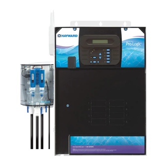
- Page 1 Pro Logic ® Automation and Chlorination Installation Manual for model PL-P-4-CUL www.haywardnet.com Canada: 888-238-POOL US: 888-921-POOL...
-
Page 2: Important Safety Instructions
IMPORTANT SAFETY INSTRUCTIONS When using this electrical equipment, basic safety precautions should always be followed, including the following: READ AND FOLLOW ALL INSTRUCTIONS • • WARNING: Disconnect all AC power during installation. • WARNING: Water in excess of 100 degrees Fahrenheit may be hazardous to your health. -
Page 3: Table Of Contents
Table of Contents Introduction Before You Begin..............1 Installation Steps..............1 1. Preparing General Water Chemistry............. Pool/Spa Water Salt..................3 2. Mounting Pro Logic Control Center............5 Equipment Temperature Sensors............. 5 Optional Chlorination .............. 5 Optional AQL-CHEM Sensing Kit......... 5 Optional AQL-CHEM2 CO Dispense Kit...... -
Page 4: Introduction Before You Begin
Utility electrical outlet and weatherproof cover (for mounting on side of Pro Logic) Mounting hardware (screws, etc.) for mounting Pro Logic and remote display/keypad Valves (use standard Hayward, Pentair/Compool, or Jandy valves) Additional valve actuators Accessory Products - Order Separately... -
Page 5: Preparing General Water Chemistry
4. Electrical Wiring (page 10) 5. Pro Logic control configuration (page 20) Main service Grounding and bonding 6. System Startup and checkout (page30) Circuit breakers Pro Logic control power High Voltage pool equipment Low voltage wiring (temperature sensors, flow switch, etc.) 1. -
Page 6: Pool/Spa Water Salt
The pool’s chemistry must be balanced BEFORE activating the Pro Logic’s optional chlorinator function. NOTE: If the pool does not have new water, add metal remover and non-copper based algaecide to the pool, per manufacturer’s instructions. This ensures a quick, troublefree transfer to the Pro Logic system. Salt (When using optional chlorinator function ) Salt Level... - Page 7 Pool Sizing Formula Liters Gallons (pool size in meters) (pool size in feet) Length x Width x Length x Width x Rectangular Average Depth x 7.5 Average Depth x 1000 Diameter x Diameter x Diameter x Diameter x Round Average Depth x 5.9 Average Depth x 785 Length x Width x Length x Width x...
-
Page 8: Mounting Pro Logic Control Center
The PL-P-4 model requires the use of a chlorinator cell and plumbing kit to provide pool chlorination. These items are not included with the Pro Logic and can be purchased separately at your local Hayward dealer. Choose a chlorinator cell model based on the size of your pool. The following models are available:... -
Page 9: Optional Aql-Chem2 Co
Pro Logic. Refer to the AQL-CHEM2 manual for specific installation information. Optional Remote Controls Hayward offers a variety of wired and wireless remote control options for the Pro Logic. Each model gives you the ability to control your pool’s functions from a remote location, away from the Control Center. -
Page 10: Optional Base Station
Note that the Pro Logic is compatible with AQL2 wireless remote controls only. A single AQL2-BASE-RF Base Station must be installed on the Pro Logic in order to use any of the Hayward wireless remote controls. With the Base Station installed, there is no limit on the number of wireless remotes that can used. The maximum distance between the wireless remotes and the base station on the Pro Logic main control unit is 400 feet (120m) line of sight or 200 feet (60m) through walls, etc. -
Page 11: Plumbing Pool/Spa Configuration
3. Plumbing Pool/Spa system configuration These systems use a single filter pump and filter. Pool or spa operation is controlled by two 3-way valves (suction and return). Refer to the diagram below. HIGH VOLTAGE LIGHTS High Voltage Relays Valve Outputs LOW VOLTAGE Filter Pump Pool/Spa Suction... -
Page 12: Turbo Cell
Turbo Cell (choose proper model for your pool) The Turbo Cell (used for chlorine generation) should be plumbed AFTER the filter and heater. If installed on a pool/ spa combination system, the cell should be plumbed BEFORE the pool/spa return valve in order to allow proper chlorination of both the pool and the spa. -
Page 13: Electrical Main Service
4. Electrical Wiring Wireless Base AQL-CHEM Connector Receiver Connector Remote Keypad “Local” Display Temp Sensor Inputs External Input Heater Output Valve Connectors Flow Switch High Voltage Cell Connector Relays Subpanel Control Power Input pH Dispense Output Bonding Lug(s) Ground Bus Bar The Pro Logic Control Center requires both high and low voltage connections. -
Page 14: General Purpose Outlet
General Purpose Outlet If desired, a duplex receptacle with weatherproof cover (supplied by installer) may be installed in the knockouts on the lower right side of the Pro Logic enclosure. Per code, the receptacle should be a GFCI type. Alternatively, connect a standard receptacle to a GFCB. - Page 15 The Pro Logic can control up to 2 Hayward TriStar VSPs and 4 EcoStar VSPs. Refer to the diagram below for proper input wiring to the VSP. Wiring from the 220V breaker must connect through the Pro Logic’s Filter/Lights/Aux relay. Refer to VSP Address Setting on page 16 to determine which relays can be used with your pump.
-
Page 16: Low Voltage Wiring
(Valve2) and return (Valve1) valves. Valve3 is for general purpose use (solar, water feature, in-floor cleaner, etc.). For installations with solar heating, Hayward offers the AQ-SOL-KIT-xx solar kit that contains a valve, actuator, and extra temperature sensor. The “xx” indicates the valve type from the 3 choices below: 1.5”... - Page 17 Fusible Link Hayward Heaters Refer to the instructions in the heater manual for “2-wire Remote Thermostat” operation under “Remote Control Connections” and the diagram below: 1. Turn off power to heater. 2. Wire Pro Logic to terminals 1 & 2 (see diagram).
- Page 18 Pentair/Purex/MiniMax 1. Turn power off to heater. 2. Remove factory installed jumper from the “Ext Switch” connector. 3. Wire the Pro Logic to the “Ext Switch” connector as shown below. 4. The wires to the Pro Logic must be separated from any line voltage wires. Failure to follow these instructions may cause erratic operation of the heater.
- Page 19 Terminal Board STA-RITE Hayward Variable Speed Pump (VSP) Wiring and Address Setting Refer to your TriStar or EcoStar manual(s) for proper low voltage communication wiring between the Pro Logic and the Hayward Variable Speed Pump. A pump address must be configured for each VSP used in the system. This address is entered into the VSP’s configuration menu.
- Page 20 Temperature Sensors The Pro Logic utilizes 10K ohm thermistor type sensors. Three sensors (water temperature, air temperature and solar temperature) are included. If the Pro Logic is being used to control a solar heating system, the solar sensor is required. The sensors are provided with a 15 ft.
-
Page 21: Flow Switch
Base Station Plug in the pigtail connector from the wireless base station into the “wireless” connector on the main PCB in the Pro Logic control unit. Connector for Base Station Base Station (AQL2-BASE-RF) Pro Logic Main PCB Tighten nut AQL-CHEM ORP and pH Sensing Kit Plug in the connector from the AQL-CHEM into one of the “COMM”... - Page 22 Hayward Aqua Rite Chlorinator The Pro Logic can control one or more Hayward Aqua Rite chlorinators when additional sanitizing capacity is re- quired. A 4 wire connection is used to communicate to the Aqua Rite and can be wired up to 500' apart. Any outdoor rated 4 conductor cable can be used.
-
Page 23: Configuration Configuration Menu
5. Configuration Menu After plumbing and wiring are complete, the Pro Logic MUST BE CONFIGURED before attempting to operate. Configuration information is entered at the keypad and “tells” the Pro Logic what equipment is connected and how each should be controlled. Accessing the Configuration Menus Configuring the Pro Logic requires that you navigate through the Configuration Menu and input various informa- tion. - Page 24 Pool/Spa Config. Push to access Pool/Spa options + to view/change Move to previous/next configuration menu Rotates between Pool Only (default), Spa Only and Pool/Spa Setup Pool and Spa Pool and Spa Move to next menu item if “Pool and Spa” is selected Spa - CountDn Adjust time setting (Manual On/Off, 0:05, 0:10, 0:15..., (default is 4:00)) 00:30...
- Page 25 2-speed and variable speed pump operation. For the Hayward variable speed pump: The Filter relay is used to supply input power to the pump. The relay will be on when the filter pump output is on. When the filter pump output is off, the relay will be off.
- Page 26 Freeze Protection Temperature Select the temperature to be used for freeze protection. Temperature is adjustable from 33ºF-42ºF (1ºC-6ºC). 38ºF (3ºC) is default. This threshold will be used for all outputs that have freeze protection enabled. External Input Interlock When enabled, the filter pump will be forced off when the external input is active. Note that freeze protection will have precedence over this feature.
- Page 27 Solar Config. Push to access solar options + to view/change Move to previous/next configuration menu Toggle between Enabled and Disabled (default) Solar Solar Disabled Move to next menu item or previous/next configuration menu if “Solar” is enabled Toggle between Enabled and Disabled (default) Solar Extend Solar-Extend Disabled Move to next menu item...
- Page 28 20% to 100% (default). The level is saved for the next time the lights are turned on. If “VSP” is selected, the Lights relay is used to supply power to a Hayward Variable Speed Pump (VSP). The relay will be on when the Lights output is on and off when the output is off . On, off and speed are...
- Page 29 Lights Interlock If enabled, this feature will override the function (Manual On/Off, Countdown Timer, Timeclock) selected above and turn the lights relay off when: filter pump is off, first 3 minutes of filter pump operation (allows the pump to prime and get water flowing), when the pool/spa suction return valves are in any position other than “pool only”, or for the first 3 minutes after solar turns on (allows air in the solar panels to be purged).
- Page 30 20% to 100% (default). The level is saved for the next time the aux1 output is turned from off to If “VSP” is selected, the Aux relay is used to supply power to a Hayward Variable Speed Pump (VSP). The relay will be on when the Aux output is on and off when the output is off.
- Page 31 Valve3 Config. Push to access Valve3 options + to view/change Move to previous/next configuration menu Rotates Timeclock (default), Solar, In-floor Cleaner and Super Chlorinate Valve3 Function Solar Move to next menu item for all functions except solar and super chlorinate Toggle between Enabled and Disabled (default) Valve3 Interlock Valve3 Interlock...
- Page 32 if AQL-SS-6B is connected 6B Spa Config. Push to access the 6 Button Spa Side Remote options + to view/change Move to previous/next configuration menu Select 6B Spa Rotates between all available remotes Move to next menu item Rotates between System Off, Pool/Spa, Filter, Lights, Heater1, 6B A, Button 1 Aux1 and Aux2 Pool/Spa...
-
Page 33: Maintenance Menu
Reset Config. to Initiate reset of all configuration parameters Default Press + Move to previous/next configuration menu (config. not reset) Are you sure? Reset all configuration parameters + to proceed Move to previous/next menu (config. not reset) Config. reset Move to previous/next configuration menu Confirmed Use this function to erase all previous system configuration and reset all configuration parameters back to the factory default values. -
Page 34: And Checkout Heater Checkout
Heater Checkout Follow these instructions to verify that the Pro Logic is properly controlling the heater. 1. Check that the Pro Logic is calling for the heater to turn on as indicated by the “Heater” LED being illuminated. If the “Heater”... -
Page 35: Warranty Pro Logic Limited Warranty
(3) years. Hayward/Goldline also warrants its Aqua Trol chlorination products to be free of defects in materials and work- manship, under normal use and service for a period of one (1) year. These warranties are applicable from the initial date of installation on private residential swimming pools in the US and Canada. - Page 36 6 button spa side remote remote menus 7-day or weekend/weekday timeclock 12 hour or 24 hour time format ºF or ºC vsp speed (% or rpm) reset to default 620 Division St. 092451 RevC Copyright © 2010 Hayward Elizabeth, NJ 07207...
Need help?
Do you have a question about the Pro Logic PL-P-4-CUL and is the answer not in the manual?
Questions and answers