HP 5500 EI Series Installation Manual
5500 ei/si series
Hide thumbs
Also See for 5500 EI Series:
- Configuration manual (424 pages) ,
- Specifications (47 pages) ,
- Lan switching configuration manual (235 pages)

Related Manuals for HP 5500 EI Series


Summary of Contents for HP 5500 EI Series
-
Page 1: Installation Guide
HP 5500 EI & 5500 SI Switch Series Installation Guide Part number: 5998-1710 Document version: 6W101-20130630... - Page 2 HEWLETT-PACKARD COMPANY MAKES NO WARRANTY OF ANY KIND WITH REGARD TO THIS MATERIAL, INCLUDING, BUT NOT LIMITED TO, THE IMPLIED WARRANTIES OF MERCHANTABILITY AND FITNESS FOR A PARTICULAR PURPOSE. Hewlett-Packard shall not be liable for errors contained herein or for incidental or consequential damages in connection with the furnishing, performance, or use of this material.
-
Page 3: Table Of Contents
Contents Preparing for installation ············································································································································· 1 Safety recommendations ·················································································································································· 1 Examining the installation site ········································································································································· 1 Temperature/humidity ············································································································································· 1 Cleanness ·································································································································································· 2 EMI ············································································································································································· 2 Laser safety ································································································································································ 2 Installation tools ································································································································································· 3 ... - Page 4 Powering on the switch·················································································································································· 28 Setting up an IRF fabric ············································································································································· 29 IRF fabric setup flowchart ·············································································································································· 29 Planning IRF fabric setup ··············································································································································· 30 Planning IRF fabric size and the installation site ································································································ 30 Identifying the master switch and planning IRF member IDs ············································································ 30 ...
- Page 5 10-GE SFP+ transceiver modules ························································································································· 51 SFP+ cables ···························································································································································· 52 10-GE XFP transceiver modules ··························································································································· 52 CX4 cables ····························································································································································· 53 Appendix C Ports and LEDs ······································································································································ 54 Ports ················································································································································································· 54 Console port ·························································································································································· 54 ...
-
Page 6: Preparing For Installation
Preparing for installation Safety recommendations To avoid any equipment damage or bodily injury caused by improper use, read the following safety recommendations before installation. Note that the recommendations do not cover every possible hazardous condition. Before cleaning the switch, unplug all power cords. Do not clean the switch with wet cloth or liquid. •... -
Page 7: Cleanness
Cleanness Dust buildup on the chassis may result in electrostatic adsorption, which causes poor contact of metal components and contact points, especially when indoor relative humidity is low. In the worst case, electrostatic adsorption can cause communication failure. Table 1 Dust concentration limit in the equipment room Substance Concentration limit (particles/m³) Dust... -
Page 8: Installation Tools
Installation tools • Flathead screwdriver Phillips screwdriver • Needle-nose pliers • • Wire-stripping pliers Diagonal pliers • ESD-preventive wrist strap • Blow dryer • All these installation tools are user supplied. -
Page 9: Installing The Switch
Installing the switch CAUTION: Keep the tamper-proof seal on a mounting screw on the chassis cover intact, and if you want to open the chassis, contact your local HP agent for permission. Otherwise, HP shall not be liable for any consequence caused thereby. -
Page 10: Installing The Switch In A 19-Inch Rack
Installing the switch in a 19-inch rack You can install the switch in a 19-inch standard rack by using different mounting positions. Table 3 shows the installation methods available for the switches of different depths. Table 3 Installation methods Use front Use front mounting Use front and mounting... -
Page 11: Mounting Brackets
Mounting brackets Figure 2 Front mounting bracket (1) Hole for attaching to a rack (by using an M6 screw) (2) Hole for attaching to the switch chassis Figure 3 Rear mounting bracket (1) Hole for attaching to a rack (by using an M6 screw) NOTE: The M6 screws for attaching the brackets to a rack are user supplied. -
Page 12: Rack-Mounting By Using Only Front Mounting Brackets
Chassis Front mounting brackets Rear mounting brackets 5500-24G-SFP EI (2 slots) One pair One pair 5500-24G-SFP EI TAA (2 slots) 5500-24G-PoE+ EI (2 slots) 5500-24G-PoE+ EI TAA (2 slots) 5500-48G-PoE+ EI (2 slots) One pair One pair 5500-48G-PoE+ EI TAA (2 slots) 5500-24G-PoE+ SI (2 slots) 5500-48G-PoE+ SI (2 slots) Rack-mounting by using only front mounting brackets... -
Page 13: Rack-Mounting By Using Front Mounting Brackets And A Rack Shelf
One person holds the switch chassis and aligns the oval holes in the brackets with the mounting holes in the rack posts, and the other person attaches the mounting brackets with M6 screws (user-supplied) to the rack, as shown in Figure Figure 5 Attaching the front mounting brackets to the rack (1) Front square-holed post... -
Page 14: Rack-Mounting By Using Front And Rear Mounting Brackets
Install cage nuts (user-supplied) in the mounting holes in the rack posts. Place the switch on the rack shelf, push it into the rack until the brackets touch the rack posts, and attach the mounting brackets with M6 screws (user-supplied) to the rack, as shown in Figure Rack-mounting by using front and rear mounting brackets This installation method is available only for the 5500-24G-PoE+ EI (2 slots), 5500-24G-PoE+ EI TAA (2... - Page 15 Install cage nuts (user-supplied) in the mounting holes in the front and rear rack posts. Attach the rear mounting brackets to the rear posts with M6 screws (user supplied), as shown Figure Figure 7 Attaching the rear mounting brackets to a rack (1) Rear square-holed post (2) Rear mounting bracket One person supports the chassis bottom with one hand, holds the front part of the chassis with the...
- Page 16 Figure 8 Mounting the switch in the rack (1) Rear panel (2) Rear square-holed post (3) Load-bearing screw (4) Rear mounting bracket The other person aligns the oval holes in the front brackets with the mounting holes in the front rack posts, and attaches the front mounting brackets with M6 screws (user supplied) to the front rack posts, as shown in Figure...
-
Page 17: Mounting The Switch On A Workbench
Figure 9 Attaching the front brackets to the rack (1) Load-bearing screw (2) Rear mounting bracket (3) Front panel (4) Screw used to attach front mounting brackets to front brackets (5) Front mounting bracket (6) Front square-holed post Mounting the switch on a workbench Verify that the workbench is sturdy and well grounded. -
Page 18: Grounding The Switch With A Grounding Strip
WARNING! Correctly connecting the switch grounding cable is crucial to lightning protection and EMI protection. The power and grounding terminals in this section are for illustration only. The power input end of the switch has a noise filter, whose central ground is directly connected to the chassis to form the chassis ground (commonly known as PGND). - Page 19 Figure 10 Connecting the grounding cable to the chassis (I) (1) Grounding sign (2) Grounding hole (3) Ring terminal (4) Grounding cable (5) Grounding screw Figure 11 Connecting the grounding cable to the chassis (II) (1) Grounding cable (2) Grounding sign (3) Grounding hole (4) Ring terminal (5) Grounding screw...
-
Page 20: Grounding The Switch With A Grounding Conductor Buried In The Earth Ground
Figure 12 Making a grounding cable connector Figure 13 Connecting the grounding cable to a grounding strip (1) Grounding post (2) Grounding strip (3) Grounding cable (4) Hex nut Grounding the switch with a grounding conductor buried in the earth ground If the installation site has no grounding strips, but earth ground is available, hammer a 0.5 m (1.64 ft) or longer angle iron or steel tube into the earth ground to serve as a grounding conductor. -
Page 21: Grounding The Switch By Using The Ac Power Cord
Grounding the switch by using the AC power cord If the installation site has no grounding strips or earth ground, you ground an AC-powered switch through the PE wire of the power cord, but must make sure: The power cord has a PE terminal. •... -
Page 22: Removing A Power Supply
CAUTION: To prevent damage to the power supply or the connector on the backplane of the powered device, insert • the power supply gently. If you encounter a hard resistance while inserting the power supply, pull out the power supply and then insert it again. If the captive screw cannot be tightly secured, verify the installation of the power supply. -
Page 23: Connecting The Power Cord
Loosen the captive screws of the power supply with a Philips screwdriver until they are completely disengaged. Grasp the handle of the power supply with one hand and pull it out a little, support the bottom with the other hand, and pull the power supply slowly along the guide rails out of the slot. NOTE: Put away the removed power supply in an antistatic bag for future use. -
Page 24: Connecting The Psr150-D/Psr150-D1 To A -48 Vdc Power Source
Figure 17 Connecting the AC power cord Connecting the PSR150-D/PSR150-D1 to a –48 VDC power source CAUTION: Identify the positive (+) and negative (-) marks on the two wires to avoid connection mistakes. To connect the PSR150-D/PSR150-D1 to a –48 VDC power source: Wear an ESD-preventive wrist strap and make sure it makes good skin contact and is well grounded. -
Page 25: Connect The Switch To A +12 Vdc Output Rps
Connect the switch to a +12 VDC output RPS This section applies to the 5500-24G EI (2 slots), 5500-24G EI TAA (2 slots), 5500-48G EI (2 slots), 5500-48G EI TAA (2 slots), 5500-24G SI (2 slots), and 5500-48G SI (2 slots) switches. To connect these switches to the RPS that provides +12 VDC output: Wear an ESD-preventive wrist strap and make sure it makes good skin contact and is well grounded. -
Page 26: Installing/Removing An Interface Card
Wear an ESD-preventive wrist strap and make sure it makes good skin contact and is well grounded. Unpack the RPS cable shipped with the RPS, identify the plug for connecting to the switch, correctly orient the plug with the RPS receptacle on the switch chassis, and insert the plug into the receptacle (see callout 1 in Figure 21). -
Page 27: Removing An Interface Card
Figure 22 Removing the filler panel over an interface card slot Hold the captive screws on the front panel of the interface card, and gently push the interface card in along the slot guide rail until the interface card is in close contact with the switch chassis (see callout 1 in Figure 23). -
Page 28: Installing/Removing A Dedicated Cx4/Sfp+ Cable
Wear an ESD-preventive wrist strap and make sure it makes good skin contact and is well grounded. Use a Phillips screwdriver to completely loosen the captive screws at both sides of the interface card. Pull the interface card along the guide rails until it completely comes out of the switch chassis. Installing/removing a dedicated CX4/SFP+ cable The dedicated CX4 and SFP+ cables for the 5500 EI and 5500 SI switches are hot swappable. -
Page 29: Accessing The Switch For The First Time
Accessing the switch for the first time Setting up the configuration environment The first time you access the switch you must use a console cable to connect a console terminal, for example, a PC, to the console port on the switch. Figure 24 Connecting the console port to a terminal Connecting the console cable Console cable... -
Page 30: Setting Terminal Parameters
Connect the RJ-45 connector to the console port of the switch. NOTE: Identify the mark on the console port and make sure you are connecting to the correct port. • The serial ports on PCs do not support hot swapping. If the switch has been powered on, connect the •... - Page 31 Figure 27 Setting the serial port used by the HyperTerminal connection Set Bits per second to 9600, Data bits to 8, Parity to None, Stop bits to 1, and Flow control to None, and click OK. Figure 28 Setting the serial port parameters Select File >...
- Page 32 Figure 29 HyperTerminal window On the Settings tab, set the emulation to VT100 and click OK. Figure 30 Setting terminal emulation in Switch Properties dialog box...
-
Page 33: Powering On The Switch
Powering on the switch Before powering on the switch, verify that the following conditions are met: The power cord is correctly connected. • The input power voltage meets the requirement of the switch. • The console cable is correctly connected. •... -
Page 34: Setting Up An Irf Fabric
Setting up an IRF fabric You can use HP Intelligent Resilient Framework (IRF) technology to connect and virtualize 5500 EI switches or 5500 SI switches into a virtual switch called an "IRF fabric" or "IRF virtual device" for flattened network topology, and high availability, scalability, and manageability. NOTE: An IRF fabric cannot have both 5500 EI and 5500 SI switches. -
Page 35: Planning Irf Fabric Setup
Step Description Plan the installation site and IRF fabric setup parameters: • Planning IRF fabric size and the installation site • Identifying the master switch and planning IRF member IDs Plan IRF fabric setup • Planning IRF topology and connections •... -
Page 36: Planning Irf Topology And Connections
Prepare an IRF member ID assignment scheme. An IRF fabric uses member IDs to uniquely identify and manage its members, and you must assign each IRF member switch a unique member ID. Planning IRF topology and connections You can create an IRF fabric in daisy chain topology, or more reliably, ring topology. In ring topology, the failure of one IRF link does not cause the IRF fabric to split as in daisy chain topology. -
Page 37: Identifying Physical Irf Ports On The Member Switches
Identifying physical IRF ports on the member switches Only the 10-GE ports on the IRF-capable interface cards listed in "Interface cards" can provide IRF connections for the 5500 EI and 5500 SI switches. To use the IRF feature, you must order the cards separately. -
Page 38: Configuring Basic Irf Settings
Figure 35 Use 2-port interface cards to set up multi-link IRF connection If both of the neighboring switches use 1-port interface cards, the port on MOD 1 on one switch • must connect to the port on MOD 2 on the other switch (see callout 1 in Figure 36). -
Page 39: Connecting The Physical Irf Ports
For more information about configuring basic IRF settings, see HP 5500 EI & 5500 SI Switch Series IRF Configuration Guide. Connecting the physical IRF ports Connect the IRF member switches as planned. NOTE: Wear an ESD-preventive wrist strap when you connect the physical IRF ports. For how to connect them, Pluggable SFP/SFP+/XFP Transceiver Modules Installation Guide Accessing the IRF fabric to verify the configuration When you are finished configuring basic IRF settings and connecting IRF ports, follow these steps to... -
Page 40: Maintenance And Troubleshooting
Maintenance and troubleshooting Power supply failure Built-in power supply failure Except the 5500-24G-SFP EI (2 slots) and 5500-24G-SFP EI TAA (2 slots) switches, all 5500 EI and 5500 SI switches use built-in power supplies and support three input modes: AC input, RPS DC input, and concurrent AC and RPS DC inputs. -
Page 41: Hot Swappable Power Supply Failure
If the system status LED is on but the RPS status LED is steady yellow, an AC input failure has occurred. Verify the following items: TThe AC power cord is securely connected to the switch, and the AC-input power receptacle on the switch and the connected AC power outlet are in good condition. -
Page 42: Configuration Terminal Problems
The 5500 EI and 5500 SI switches use built-in fans. If a fan failure occurs, contact the HP technical support for help and do not attempt to fix the problem yourself. Configuration terminal problems If the configuration environment setup is correct, the configuration terminal displays booting information when the switch is powered on. -
Page 43: Appendix A Chassis Views And Technical Specifications
Appendix A Chassis views and technical specifications The HP 5500 EI & 5500 SI Switch Series includes the models in Table Table 7 Models in the HP 5500 EI & 5500 SI Switch Series Type Product code HP description Alias HP 5500-24G EI Switch with 2 Interface JD377A 5500-24G EI (2 slots) -
Page 44: Chassis Views
Chassis views 5500-24G EI (2 slots)/5500-24G EI TAA (2 slots)/5500-24G SI (2 slots) Figure 37 Front panel (1) 10/100/1000Base-T auto-sensing Ethernet port (2) 10/100/1000Base-T Ethernet port LED (3) 1000Base-X SFP port (4) 1000Base-X SFP port LED (5) Console port (6) Seven-segment LED (Unit) (7) Port mode LED (Mode) (8) System status LED (PWR) (9) RPS status LED (RPS) -
Page 45: 5500-48G Ei (2 Slots)/5500-48G Ei Taa (2 Slots)/5500-48G Si (2 Slots)
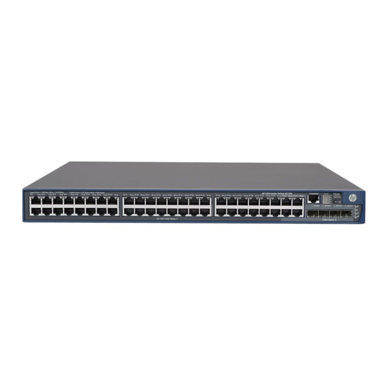
5500-48G EI (2 slots)/5500-48G EI TAA (2 slots)/5500-48G SI (2 slots) Figure 39 Front panel (1) 10/100/1000Base-T auto-sensing Ethernet port (2) 10/100/1000Base-T Ethernet port LED (3) Console port (4) Seven-segment LED (Unit) (5) Port mode LED (Mode) (6) System status LED (PWR) (7) RPS status LED (RPS) (8) Interface card 1 status LED (MOD1) (9) Interface card 2 status LED (MOD2) -
Page 46: 5500-24G-Sfp Ei (2 Slots)/5500-24G-Sfp Ei Taa (2 Slots)
5500-24G-SFP EI (2 slots)/5500-24G-SFP EI TAA (2 slots) Figure 41 Front panel (1) SFP port (2) SFP port LED (3) 10/100/1000Base-T auto-sensing Ethernet (4) 10/100/1000Base-T Ethernet port LED port (5) Console port (6) Port LED mode switching button (7) Interface card 1 status LED (MOD1) (8) Interface card 2 status LED (MOD2) (9) System status LED (SYS) (10) Power supply 1 status LED (PWR1) -
Page 47: 5500-24G-Poe+ Ei (2 Slots)/5500-24G-Poe+ Ei Taa (2 Slots)/5500-24G-Poe+ Si (2 Slots)
5500-24G-PoE+ EI (2 slots)/5500-24G-PoE+ EI TAA (2 slots)/5500-24G-PoE+ SI (2 slots) Figure 43 Front panel (1) 10/100/1000Base-T auto-sensing Ethernet port (2) 10/100/1000Base-T Ethernet port LED (3) 1000Base-X SFP port (4) 1000Base-X SFP port LED (5) Console port (6) Seven-segment LED (Unit) (7) Port mode LED (Mode) (8) System status LED (PWR) (9) RPS status LED (RPS) -
Page 48: 5500-48G-Poe+ Ei (2 Slots)/5500-48G-Poe+ Ei Taa (2 Slots)/5500-48G-Poe+ Si (2 Slots)
5500-48G-PoE+ EI (2 slots)/5500-48G-PoE+ EI TAA (2 slots)/5500-48G-PoE+ SI (2 slots) Figure 45 Front panel (1) 10/100/1000Base-T auto-sensing Ethernet port (2) 10/100/1000Base-T Ethernet port LED (3) Console port (4) Seven-segment LED (Unit) (5) Port mode LED (Mode) (6) System status LED (PWR) (7) RPS status LED (RPS) (8) Interface card 1 status LED (MOD1) (9) Interface card 2 status LED (MOD2) -
Page 49: Ports And Interface Card Slots
Chassis Dimensions Dimensions (H × W × D) Weight 5500-24G EI (2 slots) 5500-24G EI TAA (2 slots) 43.6 × 440 × 300 mm 5500-48G EI (2 slots) < 5 kg (11.02 lb) (1.72 × 17.32 × 11.81 in) 5500-48G EI TAA (2 slots) 5500-48G SI (2 slots) 5500-24G-SFP EI (2 slots) 43.6 ×... -
Page 50: Environmental Specifications
NOTE: On an HP 5500-24G-SFP EI (2 slots) or 5500-24G-SFP EI TAA (2 slots) switch, the last eight SFP ports • and the eight 10/100/1000Base-T Ethernet ports are copper/fiber combo ports in pairs, as shown Table 10. They form eight combo interfaces. When one port in a pair is activated, the other port automatically shuts down. -
Page 51: Rps Dc Input Voltage Specifications And Rps Compatibility
RPS DC input voltage specifications and RPS compatibility RPS input rated voltage Chassis Compatible RPS range 5500-24G EI (2 slots) 5500-24G EI TAA (2 slots) 5500-24G SI (2 slots) 10.8 VDC to 13.2 VDC A-RPS800 (JD183A) 5500-48G EI (2 slots) 5500-48G EI TAA (2 slots) 5500-48G SI (2 slots) 5500-24G-PoE+ EI (2 slots) -
Page 52: Cooling System
Minimum Maximum power Maximum PoE Total PoE Chassis power consumption (including power per port output consumption total PoE output) 370 W at AC input 5500-48G-PoE+ EI (2 740 W at RPS slots) 661 W at AC input DC input (370 30 W 85 W 5500-48G-PoE+ EI... -
Page 53: Appendix B Frus And Compatibility Matrixes
Appendix B FRUs and compatibility matrixes This appendix describes the FRUs available for the 5500 EI and 5500 SI switches and their compatibility. Hot swappable power supplies This section applies to the 5500-24G-SFP EI (2 slots) and 5500-24G-SFP EI TAA (2 slots) switches. Power supply Specifications •... -
Page 54: Sfp/Sfp+/Xfp Transceiver Modules And Sfp+/Cx4 Cables
Product Compatible transceiver Card model Description Support for IRF code modules/cables "GE SFP transceiver modules." Provides two Gbps NOTE: LSPM2GP2P JD367A SFP fiber ports This card does not support the transceiver module coded JD089B. Provides two 10 "10-GE SFP+ transceiver LSPM2SP2P JD368B Gbps SFP+ fiber... -
Page 55: Ge Sfp Transceiver Modules
GE SFP transceiver modules Multimode Central Cable/fiber Product fiber modal wavelength Module description diameter transmission code bandwidth (μm) distance (nm) (MHz × km) 550 m (1804.46 ft) 50/125 500 m (1640.42 ft) HP X120 1G SFP LC SX JD118B Transceiver 275 m (902.23 ft) 62.5/125... -
Page 56: 10-Ge Sfp+ Transceiver Modules
Fiber Maximum Central wavelength Product code Module Description diameter transmission (nm) (μm) distance HP X110 100M SFP LC LX 15 km (9.32 JD120B 1310 9/125 Transceiver miles) HP X110 100M SFP LC 40 km (24.86 JD090A 1310 9/125 LH40 Transceiver miles) HP X110 100M SFP LC 80 km (49.71... -
Page 57: Sfp+ Cables
SFP+ cables Product code Cable description Cable length JD095C HP X240 10G SFP+ SFP+ 0.65m DA Cable 0.65 m (2.13 ft) JD096C HP X240 10G SFP+ SFP+ 1.2m DA Cable 1.2 m (3.94 ft) JD097C HP X240 10G SFP+ SFP+ 3m DA Cable 3 m (9.84 ft) JG081C HP X240 10G SFP+ SFP+ 5m DA Cable... -
Page 58: Cx4 Cables
CX4 cables Product code Cable description Connector type Cable length HP X230 Local Connect 50cm JD363B 4X Infiniband 0.5 m (19.69 in) CX4 Cable HP X230 Local Connect 100cm JD364B 4X Infiniband 1 m (39.37 in) CX4 Cable JD365A HP X230 CX4 to CX4 3m Cable 4X Infiniband 3 m (118.11 in) Figure 48 CX4 cable... -
Page 59: Appendix C Ports And Leds
Appendix C Ports and LEDs Ports Console port Every 5500 EI or 5500 SI switch has one console port on the front panel. Table 8 Console port specifications Item Specification Connector type RJ-45 Compliant standard EIA/TIA-232 Transmission baud rate 9600 bps (default) to 115200 bps •... -
Page 60: Combo Interface
Combo interface On the 5500-24G-SFP EI (2 slots) and 5500-24G-SFP EI TAA (2 slots) switch, the last eight SFP ports • and the eight 10/100/1000Base-T Ethernet ports are copper/fiber combo ports in pairs, as shown Table 10. They form eight combo interfaces. On all the other 5500 EI and 5500 SI switches, the last four 10/100/1000Base-T Ethernet ports •... -
Page 61: System Status Led
Availability Entire series (except the 5500-24G-SFP EI (2 slots) RPS status LED and 5500-24G-SFP EI TAA (2 slots) ) Port mode LED Entire series Seven-segment LED Entire series 10/100/1000Base-T Ethernet port LED Entire series SFP port status LED Entire series Interface card status LED Entire series System status LED... -
Page 62: Port Mode Led
Table 14 RPS status LED description for the non-PoE switches LED mark Status Description Both the RPS DC input and the AC input are normal, or an RPS is Steady green connected and the AC input is normal. The RPS DC input is normal, but the AC input is disconnected or Steady yellow has failed. -
Page 63: 10/100/1000Base-T Ethernet Port Led
System status LED Seven-segment LED (Unit) status Description (PWR/SYS) status The LED displays flashing numbers. POST has failed, and the LED flashes the Flashing red ID of the failed test item. A bar rotates clockwise around the LED. Flashing green Software is loading. -
Page 64: Sfp Port Status Led
Table 19 10/100/1000Base-T auto-sensing Ethernet port LEDs description Port mode LED (Mode) Port LED status Description status The port is operating at 1000 Mbps. The port Steady green status LED fast flashes when the port is sending or receiving data. The port is operating at 10/100 Mbps. -
Page 65: Interface Card Status Led
Port mode LED (Mode) Port LED status Description status Flashing yellow (3 Hz) POST has failed on the port. No link is present on the port. The port is operating in full duplex mode. The port Steady green status LED fast flashes when the port is sending or receiving data. -
Page 66: Support And Other Resources
Support and other resources Contacting HP For worldwide technical support information, see the HP support website: http://www.hp.com/support Before contacting HP, collect the following information: • Product model names and numbers Technical support registration number (if applicable) • Product serial numbers •... -
Page 67: Conventions
• HP manuals http://www.hp.com/support/manuals HP download drivers and software http://www.hp.com/support/downloads • HP software depot http://www.software.hp.com • HP Education http://www.hp.com/learn • Conventions This section describes the conventions used in this documentation set. Command conventions Convention Description Boldface Bold text represents commands and keywords that you enter literally as shown. Italic Italic text represents arguments that you replace with actual values. - Page 68 Convention Description An alert that contains additional or supplementary information. NOTE An alert that provides helpful information. Network topology icons Represents a generic network device, such as a router, switch, or firewall. Represents a routing-capable device, such as a router or Layer 3 switch. Represents a generic switch, such as a Layer 2 or Layer 3 switch, or a router that supports Layer 2 forwarding and other Layer 2 features.
-
Page 69: Index
Index A C E F G H I L M P R S T V Interface cards,48 IRF fabric setup flowchart,29 Accessing the IRF fabric to verify the configuration,34 LEDs,55 Chassis views,39 Configuration terminal problems,37 Configuring basic IRF settings,33 Mounting the switch on a workbench,12 Connecting the console cable,24...
Need help?
Do you have a question about the 5500 EI Series and is the answer not in the manual?
Questions and answers