
Related Manuals for Kramer VM-24HDMI


Summary of Contents for Kramer VM-24HDMI
- Page 1 Kramer Electronics, Ltd. USER MANUAL Model: VM-24HDMI 2 Input 1:4 HDMI Distributor...
-
Page 2: Table Of Contents
Communication Protocol Figures Figure 1: VM-24HDMI 2 Input 1:4 HDMI Distributor Figure 2: Connecting a VM-24HDMI 2 Input 1:4 HDMI Distributor Figure 3: Connecting a PC without using a Null-modem Adapter Tables Table 1: VM-24HDMI 2 Input 1:4 HDMI Distributor Features... -
Page 3: Introduction
Scan Converters and Scalers; GROUP 8: Cables and Connectors; GROUP 9: Room Connectivity; GROUP 10: Accessories and Rack Adapters; GROUP 11: Sierra Products 2 High-Definition Multimedia Interface 3 Download up-to-date Kramer user manuals from the Internet at this URL: http://www.kramerelectronics.com 4 The complete list of Kramer cables is on our Web site at http://www.kramerelectronics.com... -
Page 4: Quick Start
Getting Started 2.1 Quick Start This quick start chart summarizes the basic setup and operation: KRAMER: SIMPLE CREATIVE TECHNOLOGY... -
Page 5: Overview
Is housed in a 19" 1U rack mountable enclosure and is fed from a 100-240 VAC universal switching power supply Control the VM-24HDMI via: The front panel buttons The infrared remote control transmitter The infrared remote extension cable transmitter, see section 4.1... -
Page 6: Defining Edid
) is a data-structure, provided by a display, to describe its capabilities to an HDMI source. The EDID enables the VM-24HDMI to “know” what kind of monitor is connected to the output. The EDID includes the manufacturer’s name, the product type, the timing data supported by the display, the display size, luminance data and (for digital displays only) the pixel mapping data. -
Page 7: Recommendations For Best Performance
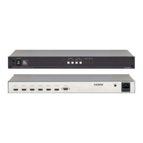
(often associated with low quality cables) Avoid interference from neighboring electrical appliances and position your VM-24HDMI away from moisture, excessive sunlight and dust Your VM-24HDMI 2 Input 1:4 HDMI Distributor Figure 1 illustrates the VM-24HDMI and Table 1 defines the front and rear panels. -
Page 8: Figure 1: Vm-24Hdmi 2 Input 1:4 Hdmi Distributor
Your VM-24HDMI 2 Input 1:4 HDMI Distributor Figure 1: VM-24HDMI 2 Input 1:4 HDMI Distributor KRAMER: SIMPLE CREATIVE TECHNOLOGY... -
Page 9: Using The Ir Transmitter
This distance can be extended to up to 60 meters when used with three extension cables Before using the external IR receiver, be sure to arrange for your Kramer dealer to insert the internal IR connection cable with the 3.5mm connector that fits into the REMOTE IR opening on the rear panel. -
Page 10: Installing In A Rack
5. The machine is earthed (grounded) in a reliable way power and is connected only to an electricity socket with If you are using a Kramer rack grounding. Pay particular attention to situations where adapter kit (for a machine that is not electricity is supplied indirectly (when the power cord 19"), see the Rack Adapters user... -
Page 11: Using The Vm-24Hdmi
5. If required, acquire the EDID (see section 6.4). 1 Switch OFF the power on each device before connecting it to your VM-24HDMI. After connecting your VM-24HDMI, switch on its power and then switch on the power on each device 2 Using the Kramer HDMI copper cables 3 As required. -
Page 12: Figure 2: Connecting A Vm-24Hdmi 2 Input 1:4 Hdmi Distributor
Using the VM-24HDMI Figure 2: Connecting a VM-24HDMI 2 Input 1:4 HDMI Distributor KRAMER: SIMPLE CREATIVE TECHNOLOGY... -
Page 13: Controlling Via Rs-232 (For Example, Using A Pc)
Using the VM-24HDMI 6.2 Controlling via RS-232 (for example, using a PC) You can connect a PC (or other controller) to the VM-24HDMI via the RS-232 port. To connect using the Null-modem adapter provided with the machine (recommended method): Connect the RS-232 9-pin D-sub rear panel port on the VM-24HDMI to... -
Page 14: Using The Edid Buttons
Using the VM-24HDMI 6.4 Using the EDID Buttons You can acquire the EDID from: One Output (the selected output LED blinks) The Default EDID (all the output LEDs blink) Several Connected Outputs, the Auto-mix Mode (the output LEDs blink in sequence) -
Page 15: Acquiring The Default Edid
1 If you want to cancel the EDID modification, wait for a few seconds without touching any button 2 The factory-default which is programmed into the VM-24HDMI before it is shipped 3 The EDID acquired is a weighted average of all the connected outputs. For example, if several displays with different... -
Page 16: Technical Specifications
Technical Specifications Technical Specifications of the VM-24HDMI: Table 3 includes the technical specifications Table 3: VM-24HDMI Technical Specifications INPUTS: 2 HDMI Connectors OUTPUTS: 4 HDMI Connectors BANDWIDTH: Supports up to 2.25Gbps bandwidth per graphic channel COMPLIANCE WITH HDMI STANDARD: Supports HDMI 1.3 and HDCP... -
Page 17: Communication Protocol
Communication Protocol Communication Protocol The VM-24HDMI is compatible with Kramer’s Protocol 2000 (version 0.50) (below). This RS-232/RS-485 communication protocol uses four bytes of information as defined below. For RS-232, a null-modem connection between the machine and controller is used. The default data rate is 9600 baud, with no parity, 8 data bits and 1 stop bit. -
Page 18: Table 5: Instruction Codes For Protocol 2000
NOTE 16 - The reply to the “REQUEST WHETHER PANEL IS LOCKED” is as in NOTE 4 above, except that here the OUTPUT is assigned with the value 0 if the panel is unlocked, or 1 if it is locked. KRAMER: SIMPLE CREATIVE TECHNOLOGY... - Page 19 EXCLUSION OF DAMAGES The liability of Kramer for any effective products is limited to the repair or replacement of the product at our option. Kramer shall not be liable for: 1. Damage to other property caused by defects in this product, damages based upon inconvenience, loss of use of the product, loss of time, commercial loss;...
- Page 20 For the latest information on our products and a list of Kramer distributors, visit our Web site: www.kramerelectronics.com, where updates to this user manual may be found. We welcome your questions, comments and feedback. Safety Warning: Disconnect the unit from the power supply before opening/servicing.
Need help?
Do you have a question about the VM-24HDMI and is the answer not in the manual?
Questions and answers