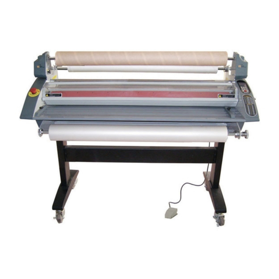
Royal Sovereign RSH-1151 Service Manual
Roll laminator
Hide thumbs
Also See for RSH-1151:
- Service manual (51 pages) ,
- Owner's manual (10 pages) ,
- Specifications (4 pages)
Table of Contents
Advertisement
Advertisement
Table of Contents

Related Manuals for Royal Sovereign RSH-1151


Summary of Contents for Royal Sovereign RSH-1151
- Page 1 ROLL LAMINATOR Service Manual www.royalsovereign.com...
-
Page 2: Table Of Contents
6.2) RSH-1651 Parts List ………………………………………………………………………………… 24 ~ 29 7. Exploded Drawings 30 ~ 44 ……………………………………………………………………… 7.1) RSH-1151 Whole Exploding Drawing and Part Exploding Drawing …………………… 31~ 37 7.2) RSH-1651 Whole Exploding Drawing and Part Exploding Drawing …………………… 38 ~ 44 8. -
Page 3: Safety Precautions
7. Ensure the unit is turned off, cooled ,and unplugged from the outlet prior to moving and/or repairing. 8. Keep out of reach of children. 9. Only Royal Sovereign authorized maintenance and service technicians should make repairs. 10. Do not attempt to laminate items that exceed total recommended material thickness for the unit. -
Page 4: Troubleshooting
2. Troubleshooting Note: While repairing: Make sure the power plug is unplugged from the power outlet. Open both side covers and rear cover. Be sure to follow the steps below in order. 2.1 Rollers Not Heating CAUSES: 1. Improper laminating mode. 2. - Page 5 3. Blown (burnt) upper and/or lower wire fuse (T/Fuse). a. Replace the T/Fuse wire located on the left-hand side. WIRE- T/FUSE 4. Defective Bi-Metal. a. Replace the Bi-Metal BI- METAL 5. Defective heater. a. Using the multi-meter, test the continuity of the heater. If it fails, replace the heater. Multi-meter b.
-
Page 6: Rollers Over Heating
2.2) Rollers Over Heating CAUSES 1. Lower and upper heat sensors are reversed on the PCB Main. 2. Defective T/Fuse wire. 3. Defective heater. 4. Defective main PCB. MEASURES 1. Wires for lower and upper heat sensors are reversed on the main PCB. a. -
Page 7: Rollers Not Running
2.3) Rollers Not Running CAUSES 1. No power to the unit. 2. Emergency switch is engaged. 3. Disengaged Paper Guide switch. 4. Opened safety cover. 5.Opened Front Table Switch. 6. Film is jammed on the rollers. 7. Disconnected motor wire. 8. - Page 8 4. Opened safety cover. a. Close the safety cover and double check to insure that the safety cover switch is engaged. Note: By closing the safety cover, it engages the safety cover switch. Safety Cover Switch Switch is engaged 4. Opened Front Table Switch. a.
- Page 9 5. Film is jammed on the rollers. a. Un-jam the film using a combination of the pressure lever and reverse button. 6. Disconnected motor wire. a. Check the motor wire connection in both locations. Motor wire connector Motor wire connector from the PCB from the Motor 7.
-
Page 10: No Main Power
2.4) No Main Power CAUSES 1. No electricity. 2. Blown main fuse. 3. Disconnected main power wires. 4. Defective transformer. MEASURES 1. No Electricity. a. Double check to insure that you have electricity from your outlet. b. Check the circuit breaker. c. -
Page 11: Count Sensor Not Working
4. Transformer is defective a. Replace the transformer. Transformer 2.5) Count Sensor Not Working.(Option) CAUSES 1. The optical fiber cable is not connected with optical fiber AMP. 2. The upper sensor is aligned properly with lower sensor. 3. The counter wires are not connected on the Main PCB. 4. - Page 12 2. The upper sensor is aligned properly with lower sensor. Upper Sensor Lower Sensor 3. The counter wires are not connected on the Main PCB. a. Ensure that the counter wires are connected to the Main PCB. Counter Wires 4. Main PCB is defective. a.
- Page 13 5. The count needs adjustment. a. Please see below for adjustments. Adjusting the Counter Sensor Throught beam Adjusting Fine Coarse Fix VR(Coarse) at ON position with turning right Initial setting slowly when it is the status of the recviced light. Min.
-
Page 14: Replacing Parts
3. Replacing Parts Note: While replacing parts: a. Make sure the power plug is unplugged from the power outlet. b. Open both side covers and rear cover. 3.1 Replacing the Right Cover. a. Take out the pressure lever (Figure 1) and four cover screws using Phillips screw driver (Figure 2). Figure 1 Figure 2 b. -
Page 15: Left Cover
3.2 Replacing the Left Cover a. Replace the Left Cover by loosening four Left Cover screws. 3.3 Replacing Rear Cover a. Take off the left and right covers. b. Take out the seven screws from the back cover. Figure 5 c. -
Page 16: Heaters
3.6 Replacing the Heaters Note: Cotton or surgical gloves are recommended while handling the heater assembly. a. Disassemble Right and Left Covers (Refer to “ Replacing Right Cover” and “Replacing Left Cover”). b. Take out the heater brackets on each side by loosening the nuts and screws (Figure 8, 9, & 10). Figure 10 Figure 9 Figure 8... -
Page 17: Adjustments
4. Adjustments 4.1 Adjusting Take-up Shaft Speed CAUSES: 1.Main rollers and take-up shaft speed is not synchronized. MEASURES: 1. Take off the take up motor cover. Figure 1 2. Loosen (increases speed) or tighten (reduces speed) the bolt using 11/16” or 17mm wrench. Note: Loosen three screws as shown in Figure 1 to get to the adjustable take-up shaft speed bolt. - Page 18 5. Installing Options Note: These options are to be installed by an authorized RS reseller. 1. Installing the Front Feeder a. Install the Left and Right Front Feed option on the inside of the front frames using four 9/16” hexagon bolts on each side. Figure 1 Figure 1 2.
-
Page 19: Rsh-1151 Parts List
6.2 RSH-1651 Parts List RSH-1651 Part N/O Part Name SPEC. Q'TY 13500X001A CASTER-STAND1 20-30S-B3-SBB-TG KYUNG CHANG(W/T BRAKE) 13500X002A CASTER-STAND2 20-30S-B3-SBB-TG KYUNG CHANG(W/O BRAKE) WSB16038D2 WASHER-SPRING SWRH Φ16.2*3.8T SUS27 212LR1004A STAND-BASE STKR 120*50*2.3T 212LR1003A STAND-FRAME STKR 3.2T 212LR1005C STAND-CENTER STKR 120*50*2.3T BHE08012D2 BOLT HEXAHEAD M8*12 SUS27 WSB08020D2 WASHER-SPRING... - Page 20 Part N/O Part Name SPEC. Q'TY 013LR2012B FRAME-SENSOR AL6063 PANTONE 421U MFC04018D2 SCREW FH M4*18 SUS27 013LR3002B FRAME-CUTTER AL6063 PANTONE 421U 023LR3003A KNOB-CUTTER,C ABS 94VO AF-312 IVORY 140LR3001A HOLDER-CUTTER,C ABS 94VO AF-312 PANTONE 420U 213LR4001A CUTTER-CROSS STS420J2 1T 138LR4001A SPRING-CROSS,CUTTER SWRH Φ0.3 ZWP5 NHB03024D2 NUT HEXAGON M3 2 SORT SUS27...
- Page 21 Part N/O Part Name SPEC. Q'TY 138LR4003A SPRING-PRESSURE SWRH φ3 ZWP5 122LR4004A BUSH-PLATE PRESSURE S45C Cu+Ni+Cr RC001500C8 SNAP RING STW-15 WON IL 141LR2012A PLATE-PRESSURE,R SPCC 3T ZWP5 363LR4001D BIMETAL-HEATER KS-2/KSD N100℃ 99 WSB03007D2 WASHER-SPRING Φ3.1*0.7T SUS27 100 223LR2003A HEATER ASS'Y FCHW1 33Ω...
- Page 22 Part N/O Part Name SPEC. Q'TY 142 12200X035A DU BUSH φ8*8 FLANGE 143 141LR4052A KNOB CAM SPCC+S45C 144 RE000600C8 E-RING ETW-6 WON IL 145 023LR4002A KNOB-BOLT GUIDE PHENOL BLK 146 136CR4001A CHAIN-TAKE UP #25 156E 147 120LR4001B SHAFT-TABLE S45C φ10 Cu+Ni+Cr 148 014LR1004B TABLE-FRONT AL6063 PANTONE 421U 149 141LR4043A FRONT TABLE SAFETY LEVER...
- Page 23 Part N/O Part Name SPEC. Q'TY 190 TFH04035D2 SCREW FH M4*35 SUS27 191 021LR2003E COVER-TAKE UP,L ABS 1/16"V-0 PA-765(94V0 AF-312) 192 TFH04018D2 SCREW FH M4*18 SUS27 193 021LR2002B COVER-R ABS 1/16"V-0 PA-765(94V0 AF-312) 194 032LR3004A SHEET-FUNC PC 0.75T 195 023LR3006A BUTTON-FUNC KE-9X1 SILICONE 196 350LR3022A PCB-SUB ASS'Y FR-4...
- Page 24 Part N/O Part Name SPEC. Q'TY 238 RE001000C8 E-RING ETW-10 WONIL 239 WPB05030H8 WASHER-PLAIN SPCC 3T*11.8*Φ5 Zn plating RIV05013E8 BRINDER RIVET AL φ5*18 241 WPB15010D2 WASHER-PLAIN 15.5*28*1.0T PZY 242 WPB06015A6 WASHER-PLAIN 6.6*12.5*1.6 FZY 243 MBC05008D2 SCREW BH M5*8 SUS27...
- Page 25 7. Exploded View 7.1 RSH-1151 Exploded View Frame L Frame R Stand Part and Frame-Base Frame,Roller and Other View Wire and Options Front Table、Safety cover and Shaft Films 7.2 RSH-1651 Explode View Frame L Frame R Stand Part and Frame-Base Frame,Roller and Other View Front Table、Safety cover and Shaft Films...
- Page 26 7.2 RSH-1651 Exploded View 381LR4032A WIRE-REMOTE;2464 24AWG4C 350CR4001A PCB-REMOCON ASS'Y 025LR4001A CASE-REMOCON ASS'Y 381LR4055A WIRE-UP HEATER 2 381LR4054A WIRE-LO HEATER 2, 381LR4037A WIRE-T/FUSE LOW 381LR4036A WIRE-T/FUSE UP 381LR4046A WIRE-COUNT; UL1007 AWG#20 381LR4044A WIRE-MAIN;26AWG20C 381LR4029A WIRE-LO HEATER,EU TEFRON WIRE 018/50 381LR4030A WIRE-UP HE ATER,EU TEFRON WIRE 018/50 381LR4083A WIRE-EMER/MOTOR...
- Page 27 Frame - L Pa r t Pa r t Na me NHB08050D2 NUT WSB06015D2 WASHER-SPRING MBC04008D2 SCREW BH WSB04010D2 WASHER-SPRING 23200X001A SUPPORT -BRACKET PCB 013LR2045A FRAME-L 141LR4007C BRACKET -SWITCH,EU 36400X002B SWITCH-MAIN 23300X001A BUSHING-CORD,EU 380LR4001A POWER CORD 36600X002A FUSE BLOCK MFC04008D2 SCREW FH 325000X005 FUSE MAIN WSB05013D2 WASHER-SPRING...
- Page 28 Frame - R Pa r t N/O Pa r t Na me MBC04008D2 SCREW BH WSB04010D2 WASHER-SPRING MFC04008D2 SCREW FH 013LR2046A FRAME-R WSB05013D2 WASHER-SPRING MBC04018D2 SCREW BH MBC05018D2 SCREW BH MPC03006D2 SCREW PH 141LR4012A PLATE-BEARING 131LR4016A SPROCKET-ROLLER,LAMI SKE06010B6 SCREW-SET SKE06015B6 SCREW-SET SKE04010B6 SCREW-SET 131LR4015A SPROCKET-ROLLER,PULL SKE04015B6 SCREW-SET...
- Page 29 Stand Part and Frame - Base Pa r t Pa r t Na me 13500X001A CASTER-STAND1 13500X002A CASTER-STAND2 WSB16038D2 WASHER-SPRING 212LR1004A STAND-BASE 212LR1003A STAND-FRAME 212LR1005C STAND-CENTER BHE08012D2 BOLT WSB08020D2 WASHER-SPRING NHB08050D2 NUT BHE08100D2 BOLT 212LR2003A STAND-TOP 013LR3006A FRAME-BASE BHE06020D2 BOLT WSB06015D2 WASHER-SPRING 211003002B BLOWER-ASS'Y...
- Page 30 Frame, Roller and Other View Pa r t Pa r t Na me MBC04008D2 SCREW BH WSB04010D2 WASHER-SPRING MBC04010D2 SCREW-BH 013LR2045A FRAME-L 013LR2046A FRAME-R 013LR2009B FRAME-FR ONT 141LR4036A BRACKET-SENSOR 021LR3003A CASE-SENSOR,UP 021LR3004A CASE-SENSOR,LO 313LR3001A SENSOR -ASS'Y 381LR4027E WIRE SENSOR MBC04018D2 SCREW BH 013LR3005A FRAME-CENTER 013LR2012B FRAME-SENSOR 013LR3002B FRAME-CUTTER...
-
Page 31: Rsh-1151 Whole Exploding Drawing And Part Exploding Drawing
Front Table、Safety Cover and Film Shafts Pa r t N/O Pa r t Na me MBC04008D2 SCREW BH WSB04010D2 WASHER-SPRING MBC05030D2 SCREW BH WSB05013D2 WASHER-SPRING SKE05015B6 SCREW-SET 107 WPB04008D2 WASHER-PLAIN 023LR4002A KNOB-BOLT GUIDE 014LR1004B TABLE-FRONT 141LR4043A FRONT TABLE SAFETY LEVER 150 MFC04006D2 SCREW FH 145LR3001A GUIDE-DOCUMENT 111LR4006A BOLT-GUIDE... - Page 32 Wires and Options Pa r t N/O Pa r t Na me BHE06020D2 BOLT WSB06015D2 WASHER-SPRING WSB04010D2 WASHER-SPRING MBC04010D2 SCREW-BH MFC04008D2 SCREW FH MBC05030D2 SCREW BH WSB05013D2 WASHER-SPRING 120 WPB13016D2 WASHER-PLAIN 138LR4006A SPRING-SLIP 141LR4005A PLATE-SHAFT,FILM 140LR4002A HOLDER-SHAFT,T 12200X022A BEARING-RADIAL TRUST 147LR4009A PAD-SLIP 141LR4006A PLATE-SLIP 112004001C...
- Page 33 8. RSH-1151/1651 Wiring Diagram RSH-1151/1651 Wiring Diagram...
- Page 34 <RSH-1151/1651 Main PCB Layout > POWER TRANSFORMER M C U ⑤ ③ ② ⑫ ④ ① ⑧ ⑥ ⑦ ⑩ ⑪ ⑨ ⑬ <Connect part> 1. Wire Main. 8. Wire Up Heater. 2. Wire Sensor Up 9. Wire Blower(3EA) 3. Wire Sensor Low 10.
- Page 35 <SUB PCB and Frame-R Heater Layout> <Length Layout> Wire Up Heater Bimetal Counter Sensor Wire Wire Main Bimetal PCB SUB Wire Low Heater <Main S/W and Count Layout> <Micro S/W and Frame-L Heater Layout> PCB Length Switch Main Wire T/Fuse (133℃) Main Fuse Wire T/Fuse(133°C)
- Page 36 <Micro S/W > Front Table Micro S/W Frame Guide Paper Micro S/W Safety Cover Micro S/W Safety Cover Micro S/W...
Need help?
Do you have a question about the RSH-1151 and is the answer not in the manual?
Questions and answers