Table of Contents
Advertisement
Quick Links
Download this manual
See also:
Owner's Manual
Advertisement
Table of Contents

Related Manuals for Royal Sovereign RSH-380SL


Summary of Contents for Royal Sovereign RSH-380SL
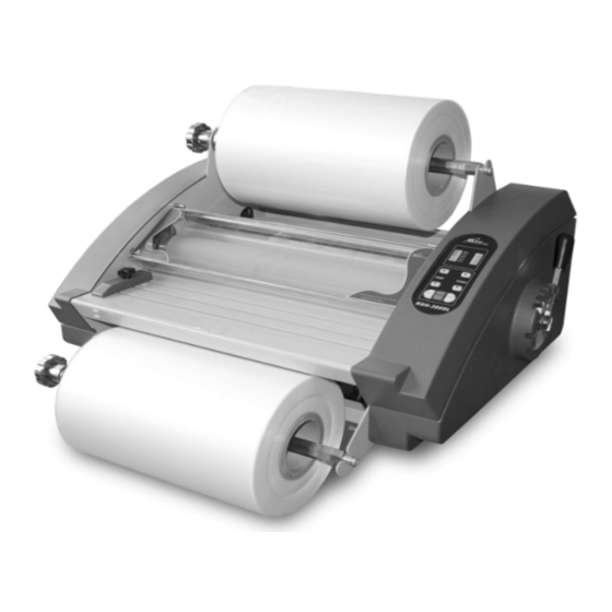
- Page 1 MODEL:RSH-380SL Roll Laminator Service Manual...
- Page 2 Table of Content 1.Safety Precautions ……………………………………………………………………… 3 ~ 3 2.Troubleshooting …………………………………………………………………………… 4 ~ 10 2.1) Rollers Not Heating ………………………………………………………………………… 4 ~ 6 2.2) Rollers Over Heating ………………………………………………………………………… 6 ~ 7 2.3) Rollers Not Running ………………………………………………………………………… 7 ~ 9 2.4) No Main Power ………………………………………………………………………………… 9 ~ 10 2.5) Poor Lamination Quality ……………………………………………………………………...
-
Page 3: Safety Precautions
7. Ensure the unit is turned off, cooled ,and unplugged from the outlet prior to moving and/or repairing. 8. Keep out of reach of children. 9. Only Royal Sovereign authorized maintenance and service technicians should make repairs. 10. Do not attempt to laminate items that exceed total recommended material thickness for the unit. -
Page 4: Rear Cover
2. Troubleshooting Note: While repairing: Make sure the power plug is unplugged from the power outlet. Open both side covers and rear cover. Be sure to follow the steps below in order. 2.1 Rollers Not Heating CAUSES: 1. Improper laminating mode. 2. -
Page 5: Heaters
2. Blown (burnt) wire fuse (T/Fuse). a. Replace the T/Fuse wire located on the left-hand side. Wire-Temp. Fuse 3. Defective Bi-Metal. a. Replace the Bi-Metal Bi-metal (135℃) 4. Defective heater. a. Using the multi-meter, test the continuity of the heater. If it fails, replace the heater. Multi-meter b. -
Page 6: Rollers Over Heating
5. Defective Main PCB. a. Replace the PCB Main. 2.2 Rollers Over Heating CAUSES 1. Heat sensor is reversed on the PCB Main. 2. Defective T/Fuse wire. 3. Defective heater. 4. Defective main PCB. MEASURES 1. Wires for lower and upper heat sensors are reversed on the main PCB. a. -
Page 7: Rollers Not Running
4. Defective Main PCB. a. Replace the PCB Main. 2.3 Rollers Not Running CAUSES 1. No power to the unit. 2. The main switch is close. 3. Opened safety cover. 4. Film is jammed on the rollers. 5. Disconnected motor wire. 6. - Page 8 Switch is engaged 4. Film is jammed on the rollers. a. Un-jam the film using a combination of the pressure lever and reverse button. 5. Disconnected motor wire. a. Check the motor wire connection with PCB. Wire-motor 6. Defective main motor. a.
-
Page 9: No Main Power
7. Defective main PCB. a. Replace the main PCB. 2.4 No Main Power CAUSES 1. No electricity. 2. Blown main fuse. 3. Disconnected main power wires. 4. Defective transformer. MEASURES 1. No Electricity. a. Double check to insure that you have electricity from your outlet. b. -
Page 10: Poor Lamination Quality
4. Transformer is defective a. Replace the transformer. Transformer 2.5 Poor Lamination Quality Problem: Straight wave lines across the output. Cause: Excessive front roller pressure. Measure: Loosen the front roller pressure. Problem: Concave waves in the lamination. Cause: Excessive rear (pulling) roller pressure. Measure: Loosen the rear back roller pressure. -
Page 11: Replacing Parts
3. Replacing Parts Note: While replacing parts: a. Make sure the power plug is unplugged from the power outlet. b. Open both side covers and rear cover. 3.1 Replacing the Right Cover. a. Take out the pressure lever (Figure 1) and four cover screws using Phillips screw driver (Figure 2). Figure 1 Figure b. -
Page 12: Left Cover
3.4 Replacing the Heaters Note: Cotton or surgical gloves are recommended while handling the heater assembly. a. Disassemble Right and Left Covers (Refer to “Replacing Right Cover” and “Replacing Left Cover”). b. Take out the heater brackets on each side by loosening screws (Figure 8, 9). Figure9 Figure8 c. -
Page 13: Adjustments
4. Adjustments C.C.W .2 Adjusting front and rear rollers Pressure • Use Screwdriver to adjust the roller pressure: C.W – Increase pressure. C.C.W – Decrease pressure. 1.Using Push-Pull Scale , measure 3 spots as shown on Figure B &C: Figure A Front roller should be 5~6 and back rollers should be 6~8. -
Page 14: Parts List
SVC Parts List RSH-380SL 125LR4001A HANDLE-TENSION S45C Cu+Ni+Cr 138LR4012A SPRING-TENSION SWP Ф3.2 12200X022A BEARING-RADIAL 15*28 141LR4033A PLATE-PRESSURE,PULL SPCC 3.0T 138LR4015A SPRING-PRESSURE SWP Ф2 141LR4032A PLATE-PRESSDURE,LAMI SPCC 3.0T 141LR4035A PLATE-DU BUSH SECC T=2.0 141LR4019A BRACKET-HEATER,UP SPCC 1.6T 36400X014B MICRO SWITCH AC 250V/5A 50-60HZ... - Page 15 φ6*8 FLANGE 12200X040A DU-BUSH 363LR4013A BIMETAL THERMOSTAL 135℃ 15A 141LP4018A BRACKET-FUSE EGI T=1 SILICON Φ7*160 147CR4003A SILICON RUBBER 23300X001A BUSHING-CORD,EU 7NR32 DONG-A S45C Φ15*42 111LR4004A BOLT-CORE ASMLR2023A ASM SENSOR RSH-380SL 381LR4020B WIRE-FUSE,EU UL1015 AWG#14 381LR4052A WIRE-MOTOR UL1007 AWG#20 BLK RED...
- Page 16 381LR4115A WIRE-MAIN UL2464 AWG#24,BLE 381LR4062B WIRE-HEATER UL1015 AWG#16 WHITE 381LR4063A WIRE-TEMP FUSE SF133E,AC250V 15A 133℃ UL1015 AWG#14 381LR4049A WIRE-BIMETAL UL1015 AWG#18, WHT 381LR4114A WIRE-HEATER LOW UL1015 AWG#16, WHT 381LR4051A WIRE-HEATER LINK UL1015 AWG#18, WHT 380LR4001A POWER CORD EU AC250V 15A 1.8M 99-1 380LR4003A POWER CORD...
- Page 17 Part No. Part Name 6.EXPLODE VIEW 021LR0001A COVER-L 125LR4001A HANDLE-TENSION 138LR4012A SPRING-TENSION 12200X022A BEARING-RADIAL 141LR4033A PLATE-PRESSURE,PULL 138LR4015A SPRING-PRESSURE 141LR4032A PLATE-PRESSDURE,LAMI 141LR4035A PLATE-DU BUSH 141LR4019A BRACKET-HEATER,UP 36400X014B MICRO SWITCH 141LR4054A BRACKET-LIMIT SWITCH 147LR4013A STOPPER-HEATER,UP 141LR4020A BRACKET-HEATER,LOW 141LR3039A PLATE-PRESSURE,L 021LR4001A LAMIT-SWITCH COVER 122LR4044A BUSH-ROLLER LAMI,UP 122LR4046A...
-
Page 18: Wire Diagram
7. Wire Diagram VCC_5V VCC_5V VCC_5V VCC_5V CA RB ON S/ W R104 SPEE D_UP S W RA101 10K x 10 Q102 U101 H/Display Com C102M PIC16C72 SPEE D_DOWN SW MCLR/Vpp LA101 RA102 LA102 RA103 C106 LDQ-N51G 330R 10P LDQ-N51R 330R 10P TEMP _UP SW 3.3/50V... - Page 19 <Connect part> 1. Wire Main. 6. Wire Power Transformer In 2. Wire Power 7. Wires Power Transformer Output 3. Wire Heater,up 8. Wire Fuse 4. Wire Heater,low 5. Motor wires...
-
Page 20: Sub Pcb
SUB PCB Bimetal(135℃) Wire Sensor Fuse Main Power Cord Wire Bimetal Motor Wire Lo Heater Wire Up Heater... - Page 21 Wire T/Fuse (133℃) Micro Switch Wire Safety S/W Wire Motor...