Table of Contents
Advertisement
Advertisement
Table of Contents

Subscribe to Our Youtube Channel
Related Manuals for Icom iM304


Summary of Contents for Icom iM304
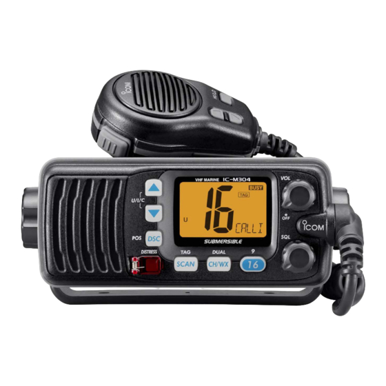
- Page 1 INSTRUCTION MANUAL VHF MARINE TRANSCEIVER iM304...
-
Page 2: Important
Icom Incor- porated (Japan) in the United States, the United Kingdom, Germany, France, Spain, Russia and/or other countries. FORCE5AUDIO logo is a registered trademark of Icom Incorporated (Japan) in the United States. IMPORTANT READ ALL INSTRUCTIONS before using the transceiver. -
Page 3: In Case Of Emergency
IN CASE OF EMERGENCY If your vessel requires assistance, contact other vessels and the Coast Guard by sending a distress call on Channel 16. USING CHANNEL 16 DISTRESS CALL PROCEDURE 1. “MAYDAY MAYDAY MAYDAY.” 2. “THIS IS ...” (name of vessel) 3. -
Page 4: Radio Operator Warning
RADIO OPERATOR WARNING Icom requires the radio operator to meet the FCC Requirements for Radio Frequency Expo- sure. An omnidirectional antenna with gain not greater than 9 dBi must be mounted a minimum W ARN ING of 5 meters (measured from the lowest point of the antenna) vertically above the main deck and all possible personnel. -
Page 5: Table Of Contents
TABLE OF CONTENTS FOREWORD …………………………………………………………… i IMPORTANT …………………………………………………………… i EXPLICIT DEFINITIONS ……………………………………………… i IN CASE OF EMERGENCY…………………………………………… ii NOTE …………………………………………………………………… ii RADIO OPERATOR WARNING ……………………………………… iii TABLE OF CONTENTS ……………………………………………… iv PRECAUTIONS ………………………………………………………… v 1 OPERATING RULES ……………………………………………… 1 2 PANEL DESCRIPTION ………………………………………… 2–4 I Front panel ………………………………………………………... -
Page 6: Precautions
This may pose a fire hazard or result in an electric shock. CAUTION: Changes or modifications to this device, not ex- pressly approved by Icom Inc., could void your authority to operate this device under FCC regulations. NEVER connect the transceiver to a power source of more than 16 V DC or use reverse polarity. -
Page 7: Operating Rules
D D PRIORITIES • Read all rules and regulations pertaining to priorities and keep an up-to-date copy handy. Safety and distress calls take priority over all others. • You must monitor Channel 16 when you are not operating on another channel. •... -
Page 8: Panel Description
PANEL DESCRIPTION I Front panel Speaker Function display (p. 4) q CHANNEL UP/DOWN KEYS [Y Y ]/[Z Z ]•[U/I/C] ➥ Selects the operating channels, Set mode settings, etc. (pgs. 5, 6, 28) ➥ While pushing and holding [SCAN], push to adjust the brightness of the LCD and key backlight. -
Page 9: I Microphone
y SCAN KEY [SCAN•TAG] (p. 11) ➥ Push to start or stop the Normal or Priority scan. ➥ Push and hold for 1 sec. to set or clear the displayed channel as a TAG (scanned) channel. • The favorite channels are set by the TAG channel setting. ➥... -
Page 10: I Function Display
PANEL DESCRIPTION I Function display q CHANNEL GROUP INDICATOR (p. 6) Indicates whether a U.S.A. “U,” International dian “C” channel is in use. w CHANNEL NUMBER READOUT ➥ Indicates the selected operating channel number. • Refer to CHANNEL LIST. (p. 36) ➥... -
Page 11: Basic Operation
I Channel selection ï ï Channel 16 Channel 16 is the distress and safety channel. It is used for establishing initial contact with a station and for emergency communications. Channel 16 is monitored during both Dual- watch and Tri-watch. While standing by, you must monitor Channel 16. - Page 12 BASIC OPERATION ï ï U.S.A.,Canadian and international channels The IC-M304 is pre-programmed with 59 U.S.A., 59 interna- tional and 63 Canadian channels. These channel groups may be specified for the operating area. q Push [CH/WX] to select a regular channel. •...
-
Page 13: I Receiving And Transmitting
I Receiving and transmitting CAUTION: Transmitting without an antenna will damage the transceiver. q Rotate [VOL] to turn power ON. w Set the audio and squelch levels. ➥ Rotate [SQL] fully counterclockwise in advance. ➥ Rotate [VOL] to adjust the audio output level. ➥... -
Page 14: I Call Channel Programming
BASIC OPERATION I Call channel programming Call channel is used to select Channel 9 (default), however, you can program the call channel with your most often-used channel in each channel group for quick recall. q Push [U/I/C] (both [Y] and [Z]) on the transceiver several times to select the desired channel group (U.S.A., Interna- tional or Canada) to be programmed. -
Page 15: I Microphone Lock Function
I Microphone lock function The microphone lock function electrically locks [Y] and [Z] keys on the supplied microphone. This prevents accidental channel changes and function access. ➥ While pushing and holding [HI/LO] on the microphone, turn power ON to toggle the Microphone lock function ON and OFF. -
Page 16: Scan Operation
SCAN OPERATION I Scan types Scanning is an efficient way to locate signals quickly over a wide frequency range. The transceiver has Priority scan and Normal scan. When the Weather alert function is turned ON, the previously selected (last used) weather channel is also checked while scanning. -
Page 17: I Setting Tag Channels
I Setting TAG channels For more efficient scanning, add desired channels as TAG channels or clear the TAG for unwanted channels. Channels that are not tagged will be skipped during scanning. TAG channels can be assigned to each channel group (U.S.A., International and Canada) independently. -
Page 18: Dualwatch/Tri-Watch
DUALWATCH/TRI-WATCH I Description Dualwatch monitors Channel 16 while you are receiving on another channel; Tri-watch monitors Channel 16 and the call channel while receiving another channel. Dualwatch/Tri- watch are convenient for monitor Channel 16 when you are operating on another channel. DUALWATCH/TRI-WATCH SIMULATION Dualwatch •... -
Page 19: Dsc Operation
I MMSI code programming The 9-digit MMSI (Maritime Mobile Service Identity: DSC self ID) code can be programmed at power ON. This code programming can be performed only twice. q Turn power OFF. w While pushing and holding [DSC], turn power ON to enter MMSI code programming condition. -
Page 20: I Dsc Address Id
DSC OPERATION I DSC address ID A total of 30 DSC address IDs (9-digit) can be programmed and named with up to 5 characters. D Programming address ID q Push [DSC] to enter the DSC menu. w Push [Y] or [Z] to select “ e Push [Y] or [Z] to select “... -
Page 21: I Position Indication
D Deleting address ID q Push [DSC] to enter the DSC menu. w Push [Y] or [Z] to select “ ” and push [DSC]. Scrolls e Push [Y] or [Z] to select “ ”, then push [DSC]. • When no address ID is programmed, “ r Push [Y] or [Z] to select the desired ID name for deleting and push [DSC]. -
Page 22: I Distress Call
DSC OPERATION I Distress call A Distress call should be transmitted if, in the opinion of the Master, the ship or a person is in distress and requires imme- diate assistance. NEVER USE THE DISTRESS CALL WHEN YOUR SHIP OR A PERSON IS NOT IN AN EMERGENCY. A DISTRESS CALL CAN BE USED ONLY WHEN IMMEDIATE HELP IS NEEDED. -
Page 23: I Transmitting Dsc Calls
I Transmitting DSC calls To ensure correct operation of the DSC function, please make sure you set the squelch correctly. (p. 7) D Transmitting Individual call The Individual call function allows you to transmit a DSC sig- nal to a specific ship only. q Push [DSC] to enter the DSC menu. - Page 24 DSC OPERATION t After transmitting the Individual call, standby on Channel 70 until an acknowledgement is received. • “ ” scrolls at the channel comment indicator. y When the acknowledgement ‘Able to comply’ is received, the specified channel (in step e) is selected with beeps automatically.
- Page 25 r Push [DSC] to enter the standby condition for Individual acknowledgement call. • “ ” appears at the channel comment indicator. t Push [DSC] to transmit the acknowledgement to the se- lected station. y After the Individual acknowledgement has been transmit- ted, the display changes to the channel specified by the calling station automatically when “...
- Page 26 DSC OPERATION r Push [Y] or [Z] to select the desired intership channel, and push [DSC]. • Channel 70 is selected and “ t Push [DSC] to transmit the Group call. • If Channel 70 is busy, the transceiver stands by until the channel becomes clear.
- Page 27 D Transmitting All Ships call Large ships use Channel 70 as their ‘listening channel.’ When you want to announce a message to these ships, use the ‘All Ships call’ function. q Push [DSC] to enter the DSC menu. w Push [Y] or [Z] to select “ Scrolls e Push [DSC] to enter the standby condition for All Ships call.
- Page 28 DSC OPERATION D Transmitting Position Request call Transmit a Position Request call when you want to know a specified ship’s current position, etc. q Push [DSC] to enter the DSC menu. w Push [Y] or [Z] to select “ e Push [Y] or [Z] to select the desired pre-programmed in- dividual address.
- Page 29 D Transmitting Position Report call Transmit a Position Report call when you want to announce your own position to a specific ship and to get an answer, etc. q Push [DSC] to enter the DSC menu. w Push [Y] or [Z] to select “ Scrolls e Push [Y] or [Z] to select the desired pre-programmed in- dividual address.
-
Page 30: D Receiving A Distress Call
DSC OPERATION I Receiving DSC calls D Receiving a Distress call While monitoring Channel 70 and a Distress call is received: ➥ The emergency alarm sounds. • Push any key to stop the alarm. ➥ “DSC” appears and “ comment indicator, then Channel 16 is automatically se- lected. -
Page 31: D Receiving An Individual Call
D Receiving an Individual call While monitoring Channel 70 and an Individual call is re- ceived: ➥ The emergency alarm or beeps sound depending on the received category. ➥ “DSC” appears and “ ” scrolls at the channel comment indicator. ➥... -
Page 32: Receiving A Geographical Area Call
DSC OPERATION D Receiving an All Ships call While monitoring Channel 70 and an All Ships call is received: ➥ The emergency alarm sounds when the category is ‘Dis- tress’ or ‘Urgency’; 2 beeps sound for other categories. ➥ “DSC” appears and “ comment indicator. -
Page 33: D Receiving A Position Request Call
D Receiving a Position Request call While monitoring Channel 70 and a Position Request call is received: ➥ “DSC” appears and “ nel comment indicator. ➥ Push any key to stop the beep, then push [DSC] to reply to the call; push any other key to ignore the call. D Receiving a Position Report call While monitoring Channel 70 and a Position Report call is re- ceived:... -
Page 34: Set Mode
SET MODE I Set mode programming Set mode is used to change the conditions of the trans- ceiver’s functions: Scan type (Normal or Priority,) Scan re- sume timer, Weather alert, Dual/Tri-watch, DSC watch, Beep tone, Auto acknowledgement and Favorite channel function. Available functions may differ depending on dealer setting. -
Page 35: I Set Mode Items
I Set mode items D Scan type The transceiver has 2 scan types: Normal scan and Priority scan. Normal scan searches all TAG channels in the selected channel group. Priority scan searches all TAG channels in se- quence while monitoring Channel 16. Normal scan (default) D D Scan resume timer The scan resume timer can be selected as a pause (OFF) or... - Page 36 SET MODE D D DSC watch DSC watch monitors Channel 70 while you are receiving an- other channel. If a distress signal is received on Channel 70, the transceiver monitors Channel 16 and 70 alternately until the distress sig- nal disappears. If a signal is received on another channel, DSC watch pauses until the signal disappears.
-
Page 37: I Connections
CONNECTIONS AND MAINTENANCE I Connections q EXTERNAL SPEAKER LEAD Connects to an external speaker. Blue: Speaker (+) Gray: Speaker ( ) w GPS RECEIVER LEAD Connects to a GPS receiver for position indication. • An NMEA0183 ver. 2.0 or 3.01 (sentence formatters RMC, GGA, GNS, GLL) compatible GPS receiver is required. -
Page 38: I Supplied Accessories
CONNECTIONS AND MAINTENANCE I Supplied accessories The following accessories are supplied: Mounting bracket For mounting bracket Knob bolts Flat washers (M5) Microphone hanger DC power cable and screws (3 16) Warning sticker I Antenna A key element in the performance of any communication sys- tem is the antenna. -
Page 39: I Mounting The Transceiver
I Mounting the transceiver D D Using the supplied mounting bracket The universal mounting bracket supplied with your transceiver allows overhead or dashboard mounting. • Mount the transceiver securely with the 2 supplied screws 20) to a surface which is more than 10 mm thick and can support more than 5 kg. -
Page 40: I Optional Mb-69 Installation
CONNECTIONS AND MAINTENANCE I Optional MB-69 installation An optional MB-69 FLUSH MOUNT transceiver to a flat surface such as an instrument panel. CAUTION: KEEP the transceiver and microphone at least 1 meter away from your vessel’s magnetic navigation com- pass. q Using the template on p. -
Page 41: Troubleshooting
PROBLEM POSSIBLE CAUSE The transceiver does • Bad connection to the power supply. not turn ON. No sound from speaker. • Squelch level is too high. • Volume level is too low. • Speaker has been exposed to water. Transmitting is impossi- •... -
Page 42: Channel List
CHANNEL LIST Channel number Frequency (MHz) CAN Transmit Receive 156.050 160.650 156.050 156.050 156.100 160.700 156.150 160.750 156.150 156.150 156.200 160.800 04A 156.200 156.200 156.250 160.850 05A 156.250 156.250 156.300 156.300 156.350 160.950 07A 156.350 156.350 156.400 156.400 156.450 156.450 156.500 156.500 156.550 156.550 156.600 156.600... -
Page 43: Specifications And Options
I Specifications ï ï General • Frequency coverage : Transmit 156.025–157.425 MHz Receive 156.050–163.275 MHz • Mode : FM (16K0G3E) DSC (16K0G2B) • Channel spacing : 25 kHz • Current drain (at 13.8 V) : TX (at 25 W) Max. audio •... -
Page 44: Specifications
SPECIFICATIONS D D Dimensions 137.0 (5 ⁄ 153.0 (6 ⁄ I Options • MB-69 For mounting the transceiver to a panel. • MB-92 For attaching to the front panel of the transceiver to protect it when not in use. 42.2 86.3 (3 ⁄... -
Page 45: Template
NOTE: The solid line is the line to use when cutting into the dash/helm. The dotted line shows the outline of the IC-M304’s front panel once the radio is fitted into the hole. Do not follow the dotted line when making the hole in your dash/helm. TEMPLATE 153.0 (6 ⁄... - Page 47 MEMO...
- Page 48 A-6542D-1US Printed in Japan 1-1-32 Kamiminami, Hirano-ku, Osaka 547-0003, Japan 2006 Icom Inc. ©...
Need help?
Do you have a question about the iM304 and is the answer not in the manual?
Questions and answers