
Related Manuals for Superlux UT6 Series


Summary of Contents for Superlux UT6 Series
-
Page 1: User Manual
User Manual UT6 series UHF wireless microphone system UT6_UM.indd 1 2009/5/7 04:20:31... - Page 2 UT6_UM.indd 2 2009/5/7 04:20:31...
-
Page 3: Table Of Contents
Contents Preface: ………………… Unpacking ………………… Receiver Introduction ………………… Front view ………………… Rear view ………………… Receiver Connections ………………… Receiver Operation ………………… Receiver Installation ………………… Receiver LCD operation ………………… LCD layout and buttons ………………… Menu function ………………… 7.2.1 Locking and unlocking ………………… 7.2.2 G/CH: Display group and channel setting …………………... -
Page 4: Preface
1. Preface 2. Unpacking Thank you for choosing the Superlux 1 x dual plug cable UT6 series UHF wirelss microphone. 1 x power supply This remarkable component has been 1 x user manual engineered to provide superb sound 1 x warranty card... - Page 5 Page. 3 UT6_UM.indd 3 2009/5/7 04:20:34...
-
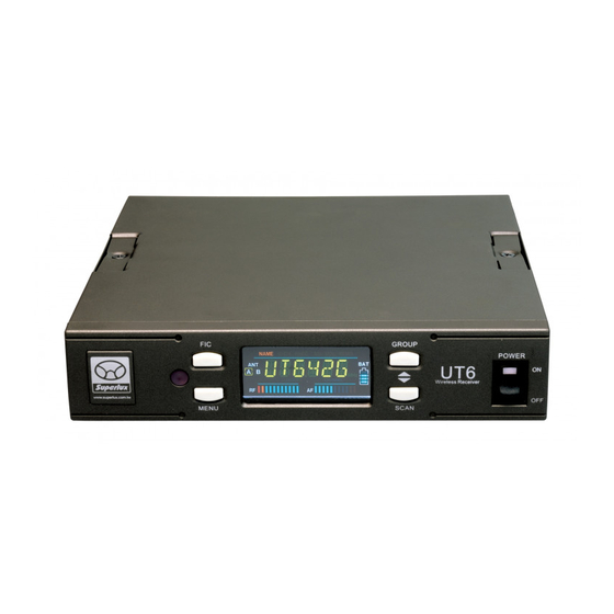
Page 6: Receiver Introduction
single channel receiver 3. Receiver Introduction Front view ① Illustration 1 Front panel antenna A socket: for optional antenna extension from rear panel. ② Front panel antenna B socket: for optional antenna extension from rear panel. Rear view ⑥ Antenna B socket Illustration 2 ⑤... - Page 7 single channel receiver ④ Power switch: LED indicator lighted when power-on. ③ Color LCD display panel ⑦ Balanced audio output, XLR-3M, microphone level ⑧ Un-balanced audio level switch: Switch between “MIC” or “LINE” level for un-balanced output socket. ⑨ Un-balanced audio output socket: 6.3mm phone jack, level switchable ⑩...
-
Page 8: Receiver Connections
single channel receiver 4. Receiver Connections Illustration 3 ⑥ ⑪ Connect both antenna to rear panel socket as illustration 3. ⑩ Connect power adapter output to receiver and plug into power line (Caution: check power source specification, make sure the power adapter matches the source spec. - Page 9 single channel receiver Ground Signal + Signal - Illustration 4 4.3.2 Un-balanced connection: When receiver and mixer are positioned at short distance, 6.3mm phone type plugs can be used with un- balanced connection. 4.3.3 Balanced connection: When receiver is located at a remote loca- tion from mixer, balanced XLR cable shall be used.
-
Page 10: Receiver Operation
single channel receiver 5. Receiver Operation Set mixer/amplifier input level to minimum or mute the channel. Turn on the receiver, the indicator shall be lighted to show the operation status. Power up the matched channel transmitter, the RF level indication shall be lighted. -
Page 11: Receiver Installation
single channel receiver 6. Receiver Installation Single receiver half width space rack mouting 6.1.1 Mount the rack mouting kit with receiver according to illustration 5. Illustration 5 Dual receivers, full width space rack mouting 6.2.1 Unscrew the 4 screws according to the illustration 6. 6.2.2 Mount the connection plate with previous 4 screws to interlock the 2 receivers. - Page 12 single channel receiver After the rack mount kit was properly installed, the receiver(s) can be mounted into EIA standard rack for 1 space height, as illustrated. For best receiption, receiver shall be located at least 1 meter above ground. Transmitter shall be at least 1 meter away and keep away from noise as illustra- tion.
-
Page 13: Receiver Lcd Operation
single channel receiver 7. LCD operation LCD layout and buttons Menu Function Menu: To access function menu By pressing this button, user can go through selections of function: NAME G/CH FREQ 7.2.1: Locking and unlocking To lock in order to prevent mis-operating, press MENU and hold for more than 3 seconds until LCD shows “LOCK”. -
Page 14: G/Ch: Display Group And Channel Setting
single channel receiver 7.2.2 G/CH: Displaying group and channel setting and changing. A: GROUP setting steps: save MENU G/CH MENU GROUP & exit B: Group setting detail: Press MENU key, select G/CH, LCD displaying 2 double digit number as GROUP and CHANNEL connected with a dash line. -
Page 15: Freq: Display Frequency In Use
single channel receiver C: CHANNEL setting steps: save MENU G/CH MENU SCAN & exit D: Channel setting ▼ Press MENU to select G/CH functon. Press SCAN key once, CHANNEL double digit flashes indicating ready for setting. ▼ Pressing SCAN again, receiver start to scan channels and stop at the first avail- able channel. -
Page 16: Sq: Squelch Setting
single channel receiver 7.2.4 SQ: Squelch setting and change A: SQ setting steps: save MENU MENU 01 ↑↓ & exit DOWN B: SQ setting detail SQuelch range from 01 to 99. ▲ ▼ Pressing UP or DOWN to change value. Press MENU to confirm store and exit. -
Page 17: Vol: Display Volume On Or Mute
single channel receiver 7.2.5 VOL: Display Volume ON or MUTE. A: VOL setting steps: save MENU MENU MUTE ↑↓ & exit DOWN B: VOL setting detail ▲ ▼ Pressing UP or DOWN to change from ON to MUTE and cycling. Press MENU to confirm store and exit. -
Page 18: Name: Displaying And Naming Receiver
single channel receiver 7.2.6 NAME: Displaying and naming receiver A: NAME setting steps: MENU NAME MENU A ↑↓ DOWN save MENU A_ ↑↓ & exit DOWN B: NAME setting detail NAME up to 6 characters, alphabets upper case, numbers, +, -, *, /, and space. ▲... -
Page 19: Fic, Frequency Infrared Control
single channel receiver 7.3 FIC function, Frequency IR Control A: FIC setting steps: exit B: FIC setting detail When the function is set at G/CH mode, press FIC key momentaryly will activating FIC operation and LCD will display “FIC”. Put microphone with FIC window facing receiver within 30 cm as illustration. As soon as microphone channel was sync with receiver, FIC operation completed and LCD resume. -
Page 20: Receiver Cautions
single channel receiver 8, Receiver Cautions DC supplier shall be no less than 12VDC to operate normally, and shall not exceed 15VDC in order not to damage the receiver. Power capacity shall be at least 1A and regulated. Please use supplied antenna to ensure receiption performance. Antenna socket provide 8VDC output, please do not short circuit. -
Page 21: Receiver Accessories
Receiver Accessories AT0 Dipple 1/4ƛ antenna, omni directional receiption provides improved signal captures than the standard antennas. AT1 Active logrithm directional antenna provides 6dB antenna gain, and 13dB amplifier gain. AT2 Antenna amplifier.13dB gain for 620~960MHz band. UDA28 Antenna distribution amplifer. Distributes 1 pair of antenna to 4 receiv- ers. -
Page 22: Handheld Wireless Microphone
Hand Held Wireless Microphone 10. Handheld wireless microphone 10.1 Introduction Illustration 10 Mesh grill: Protecting capsule, and function as pop filter. Capsule: Sound pick up element Upper tube: To hold capsule, grill, transmitter PCB and battery holder. Lower tube: Protecting battery holder and battery. Color coded cover: Protect switch and preventing from mis-operation. -
Page 23: Inserting Batteries
Hand Held Wireless Microphone 10.2 Inserting batteries Illustration 11 ④ 10.2.1 Un screw lower tube to open battery holder. ⑦ 10.2.2 Insert 2 x AA batteries, positive toward grill into battery holder 10.2.3 Screw lower tube back to place as illustration. p.s. -
Page 24: Lcd
Hand Held Wireless Microphone 10.3 LCD 10.3.1 GROUP CHANNEL to display operating at pre-defined channel. 10.3.2 CHANNEL to display operating at user defined frequency (through PC setting) 10.3.3 Battery capacity, when reaching 10%, it is time to change new batteries. If battery is too low, LCD will disply PoFF and switch off to prevent over discharge. -
Page 25: Color Coded Cover
Hand Held Wireless Microphone 10.4 Color coded cover Illustration 12 10.4.1 When the openning of the cover facing the same direction as the power switch, the switch can be operated freely. 10.4.2 For professional application, to prevent accidentally power switch operation, the cover can be removed and change direction to cover the power switch as illustration. -
Page 26: Beltpack Transmitter
Bodypack Wireless Transmitter 11. Bodypack wireless transmitter 11.1 Introduction Illustration 14 Page. 24 UT6_UM.indd 24 2009/5/7 04:20:41... - Page 27 Bodypack Wireless Transmitter Audio input socket: For various microphone inputs (Refer to Wiring illustration for 5 variations). Power switch: Set to “ON” when in use, set to “OFF” when not in use and save power. Power indicator: Indicating battery capacity. At the moment powe switch set to “ON”, indicator flash to indicate battery is good;...
-
Page 28: Operating
Bodypack Wireless Transmitter 11.2 Operating 11.2.1 Press both side latches of battery cover and open. GT/MT switch and gain adjustment can be operated. 11.2.2 Switch on the transmitter, the battery indicator shall flash to indicating batteries is still good. If indicator did not flash, indicating batteries drained or not properlly inserted. -
Page 29: Wiring For Audio Input
Bodypack Wireless Transmitter 11.3 Wiring for audio input 11.3.1 Wiring 2-conductor electret microphone bias resistor 11.3.2 Wiring 3-conductor electret microphone 11.3.3 Wiring dynamic microphone 11.3.4 Wiring electric guitar Illustration 17 Page. 27 UT6_UM.indd 27 2009/5/7 04:20:41... -
Page 30: Lcd
Bodypack Wireless Transmitter 11.4 LCD 11.4.1 GROUP CHANNEL to display operating at pre-defined channel. 11.4.2 CHANNEL to display operating at user defined frequency (through PC setting) 11.4.3 Battery capacity, when reaching 10%, it is time to change new batteries. If battery is too low, LCD will disply PoFF and switch off to prevent over discharge. -
Page 31: Batteries Exchange
Bodypack Wireless Transmitter 11.5 Changing batteries 11.5.1 Press both side latches of battery cover and open it. 11.5.2 Remove the batteries as illustration. 11.5.3 Inserting 2 x AA batteries as indicated polarity into battery holder as illustration. 11.5.4 Latch the battery cover in position. Illustration 18 Note: When microphone not in use, switch off the power. -
Page 32: Specification
Specification 12. Technical Specifications 12.1 Receiver Frequency Range Refer to the frequency table Carrier Mode PLL synthesized Channels Space between chennels 125KHz Frequency Width 24MHz Carrier stability ±5ppm≤10KHz Image interference ratio >70dB Audio frequency response 50Hz~18KHz Signal to noise ratio >105dB T.H.D. - Page 33 12.3 Beltpack Transmitter Frequency Range Refer to the frequency table Carrier Mode PLL synthesized Channels Space between chennels 125KHz Frequency Width 24MHz Carrier stability ±0.005% Maximum deviation ±48KHz Harmonic radiation <-60dBc Transmittion power 20mW Frequency setting Infrared control by receiver Dynamic range >110dB Function display...
-
Page 34: Capsules For Handheld Microphone
Capsules for handheld D108A 125º 100Hz 1KHz 10KHz 2KHz 250Hz 0º 8KHz 135º 500Hz 90º 180º 250 Hz 2000 Hz 500 Hz 4000 Hz 1000 Hz 8000 Hz 250 Hz 2000 Hz 500 Hz 4000 Hz 1000 Hz 8000 Hz 1000 2000 5000... -
Page 35: Microphones For Beltpack Transmitter
Microphones for beltpack 250 Hz 2000 Hz 500 Hz 4000 Hz 1000 Hz 8000 Hz 250 Hz 2000 Hz 500 Hz 4000 Hz 1000 Hz 8000 Hz 1000 Hz 1000 Hz WO-518BD/XLR low frequency roll-off Page. 33 UT6_UM.indd 33 2009/5/7 04:20:49... -
Page 36: Knowing Your Microphone
Knowing your microphone Superlux provides variety selection of microphones for professionals and amatures. To know your microphone is the first step to successful result. Type of transducer Dynamics Condenser Extremely light weight diaphragm, very sensitive to Durable and simple structure, operates in all kinds of sound. - Page 37 Directivity Select or set the directivity of your microphone for stereo recording, for various music instru- ment, vocal, speech, and environmental sound pick-up. Pair of spaced omni for A/B stereo, pair of near coincident cardioid for ORTF, and pair of coincident figure-8 at 90° setting for Blumlein stereo.
-
Page 38: Mounting The Microphone
Choose heavy duty microphone stand for studio condenser microphone which weights much more than handle microphone. Superlux provides wide range of microphone stands for various demands. Big Foot Willie is specially developed for large condenser microphones that able to support 2 large micro- phones with stereo bracket for single point stereo recording. - Page 39 Page. 37 UT6_UM.indd 37 2009/5/7 04:20:50...
- Page 40 Tel: +886-2-26931323 Fax: +886-2-26938990 E-mail: sales@superlux.com.tw superlux.tw Page. 38 UT6_UM.indd 38 2009/5/7 04:20:50...
Need help?
Do you have a question about the UT6 Series and is the answer not in the manual?
Questions and answers