Powerhouse PH3100Ri Operating Instructions Manual
Digital inverter generator
Hide thumbs
Also See for PH3100Ri:
- Shop manual (69 pages) ,
- Owner's manual (46 pages) ,
- Quick start manual (8 pages)

Related Manuals for Powerhouse PH3100Ri


Summary of Contents for Powerhouse PH3100Ri
-
Page 1: Operating Instructions
PH3100Ri Digital Inverter Generator Operating Instructions OPERATING INSTRUCTIONS PLEASE READ THIS MANUAL CAREFULLY BEFORE USING PH3100Ri OM revision 2010-10-07... -
Page 2: Quick Start
QUICK START Use outdoors only. Generators produce carbon monoxide — a poisonous, colorless, odorless gas that can cause death or serious injury. Always operate on a level surface Keep away from rain, snow or other wet conditions ... -
Page 3: Preface
PREFACE Thank you for purchasing a POWERHOUSE generator. This manual covers the operation and maintenance of the POWERHOUSE generator model PH3100Ri. All information in this publication is based on the latest product information available at the time of approval for printing. -
Page 4: Fcc Information
FCC INFORMATION Trade Name: Coast Distribution Inc. Model: PH3100Ri This device complies with Part 15 of the FCC Rules. Operation is subject to the following two conditions: (1) this device may not cause harmful interference, and (2) this device must accept any interference received, including interference that may cause undesired operation. -
Page 5: Table Of Contents
3.4 Connecting the battery ............................14 4. OPERATING INSTRUCTIONS ........................15 4.1 High Altitudes ..............................15 4.2 Ambient Temperature............................15 4.3 Starting Procedure for PH3100Ri: ........................16 4.4 Operation ................................18 4.5 AC Power Applications ............................19 4.6 Overload & Run Lights ............................19 4.7 DC Power Application ............................ - Page 6 6. TRANSPORTING & STORAGE ........................31 6.1 Exercising the Generator: ..........................31 6.2 Before storing the unit for an extended period: ....................32 7. TROUBLESHOOTING ..........................33 7.1 Engine will not start: ............................33 7.2 Appliance does not operate: ..........................34 7.3 No output at the DC receptacle: .........................
-
Page 7: Safety Instructions
1. SAFETY INSTRUCTIONS ■ This generator is designed to give safe and dependable service if operated according to instructions. Read and understand the Owner's Manual before operating the generator. Failure to do so could result in personal injury or equipment damage. ■... - Page 8 ■ Always make a pre-operation inspection before you start the engine. You may prevent an accident or equipment damage. ■ Place the generator at least 3 ft (1 m) away from buildings or other equipment during operation. ■ Operate the generator on a level surface. If the generator is tilted, fuel spillage may result.
-
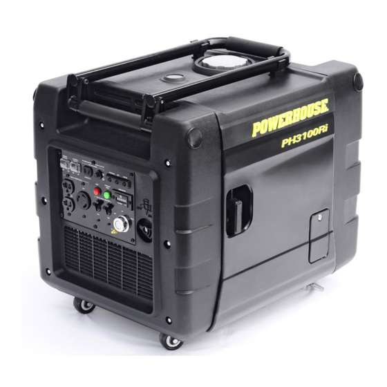
Page 9: Component Identification
2. COMPONENT IDENTIFICATION 2.1 PH3100Ri Generator Fold over handle Maintenance Cover Locking Wheels Fuel Cap Fuel Gauge Starter Grip Control Panel Engine Oil Access Cover Fuel Valve Swivel Wheels PH3100Pi OM Revision 2010-10-07... -
Page 10: Ph3100Ri Control Panel
2.2 PH3100Ri Control Panel Stop Button (Red) Run Light Overload Light Low Oil Light Battery Charge Circuit Breaker 12 V DC 8.3 A Battery Charge Receptacle Remote Control Switch Stop Button (Red) Economy Switch Hour Meter Reset Button (Green) 120 V AC 20 A... -
Page 11: Serial Number And Bar Code Identification And Location
Date of Purchase ________________________________ Name of Selling Dealership ________________________________ Please go to www.powerhouse-products.com/register and register your unit today. Online registration will be accepted as proof of purchase. Online registration will make sure you are protected in the event you have lost your receipt, and will significantly speed the process in the event warranty service is necessary. -
Page 12: Pre-Operation Check
3. PRE-OPERATION CHECK Be sure to check the generator on a level surface with the engine stopped and both wheel brakes locked. Brake 3.1 Checking the Engine Oil Level Do not use non-detergent oil or 2-stroke engine oil. It will void the warranty and will shorten the engine's service life. -
Page 13: Fuel
Running the engine with insufficient oil can cause serious engine damage. The Low Oil Alarm System will automatically stop the engine before the oil level falls below a safe limit. However, to avoid the inconvenience of an unexpected shutdown, it is still advisable to visually inspect the oil level regularly. -
Page 14: Air Filter
3.3 Air Filter Check the air filter to be sure it is clean and in good condition. 1. Loosen the cover screws and remove the maintenance cover. 2. Remove three cartridge retaining screws. Remove the air cleaner cartridge and check the filter. Clean or replace the filter if necessary. -
Page 15: Operating Instructions
4. OPERATING INSTRUCTIONS When starting the generator after adding fuel for the first time or after long term storage, or after running out of fuel, turn the fuel valve to the "on" position, then wait for 10 to 20 seconds before starting the engine. 4.1 High Altitudes At high altitude, the standard carburetor air-fuel mixture will be excessively rich, performance will decrease, and fuel consumption will increase. -
Page 16: Starting Procedure For Ph3100Ri
4.3 Starting Procedure for PH3100Ri: The unit can be started by either the ignition key or remote. When the unit is started with the ignition key, it can be shut down by the ignition key or the Emergency shut-down button on the control panel; but NOT by the remote. - Page 17 Using the Remote Before starting the engine, disconnect any load from the AC receptacles. Start Button 1. Turn the remote switch to the ON position. 2. Turn the fuel valve to the ON position. 3. Push the start button on the remote twice and hold until the engine has started.
-
Page 18: Operation
4.4 Operation Be sure to ground the generator when loads are connected. To prevent electrical shock from faulty appliances, the generator should be grounded. Connect a length of heavy cable between the generator's grounding terminal and an external ground source. Connections for standby power to a building's electrical system must be made by a qualified electrician and must comply with all applicable laws and electrical codes. -
Page 19: Ac Power Applications
4.5 AC Power Applications 1. Start the engine and make sure the green run light comes on. 2. Confirm that the appliance to be used is switched off, then, plug in the appliance. Be sure that all appliances are in good working order before connecting them to the generator. -
Page 20: Dc Power Application
4.7 DC Power Application The DC receptacle may be used for charging 12 volt lead acid batteries only. Other types of batteries may burst causing personal injury or damage. To prevent the possibility of creating a spark near the battery, connect the charging cable first to the battery then to the generator. -
Page 21: Economy Switch
The battery gives off explosive gases; keep sparks, flames and cigarettes away. Provide adequate ventilation when charging. The battery contains sulfuric acid (electrolyte). Contact with skin or eyes may cause severe burns. Wear protective clothing and a face shield. If electrolyte gets on your skin, flush with water. -
Page 22: Low Oil Alarm System
4.9 Low Oil alarm system Low Oil The generator is designed to prevent engine damage caused by an insufficient amount of oil in the crankcase. Before the oil level in the crankcase falls below a safe limit, the low oil sensor will automatically shut down the engine (the engine switch will remain in the ON position). -
Page 23: Maintenance
Carbon monoxide is a poisonous gas. The emission of fuel vapors is a source of pollution as well. The POWERHOUSE generator engine utilizes a precise air-fuel ratio and emission control system to reduce the emissions of carbon monoxide, , hydrocarbons, and evaporative fuel emissions. - Page 24 You can trust the replacement parts supplied by POWERHOUSE have been manufactured to the same production standard as the original parts. The use of replacement parts or accessories which are not designed by POWERHOUSE may affect the engine emission performance.
-
Page 25: Maintenance Schedule
5.1 Maintenance Schedule Regular Service period (1). Perform at every indicated month or operating hour interval, whichever occurs first. Maintenance Item Procedure Month Every 3 Months Every 6 Months 1x per Year Each Use 20 Hours 50 Hours 100 Hours 300 Hours Check Engine Oil... -
Page 26: Changing Oil
5.2 Changing oil Drain the oil while the engine is still warm to assure rapid and complete drainage. ■ Make sure to turn the ignition switch ―OFF‖ before draining. Upper Limit Upper level Lower Limit Lower level 1. Loosen the oil access cover screw and remove cover. 2. -
Page 27: Air Cleaner Service
5.3 Air cleaner service Check the air filter to be sure it is clean and in good condition. 1. Loosen the cover screws and remove the maintenance cover. 2. Remove three cartridge retaining screws. Remove the cartridge and check the filter. 3. -
Page 28: Spark Plug Service
5.4 Spark plug service Recommended spark plug: F7RTC To ensure proper engine operation, the spark plug must be properly gapped and free of deposits. 1. Loosen the cover screws and remove the maintenance cover 2. Remove the spark plug cap. 3. - Page 29 4. Clean any dirt from around the spark plug base. 5. Visually inspect the spark plug. Discard it if the insulator is cracked or chipped. 6. Clean the spark plug with a wire brush if it is to be reused. 7.
-
Page 30: Spark Arrester Maintenance
5.5 Spark arrester maintenance If the generator has been running, the muffler will be very hot. Allow it to cool before proceeding. The spark arrester must be serviced every 100 hours to maintain its efficiency. Spark Arrestor Clamp Exhaust Grill 1. -
Page 31: Transporting & Storage
6. TRANSPORTING & STORAGE To prevent fuel spillage when transporting or during temporary storage, the generator should be secured upright in its normal operating position with the fuel valve and engine switch turned OFF. When transporting the generator: ■ Do not overfill the tank. ■... -
Page 32: Before Storing The Unit For An Extended Period
6.2 Before storing the unit for an extended period: 1. Be sure the storage area is free of excessive humidity and dust. 2. Regardless of whether you plan to store your generator with or without fuel, add an appropriate amount (per the instructions on the bottle) of fuel stabilizer and run the generator for 5 minutes. This will assure that any fuel trapped in the system will have the stabilizer in it. -
Page 33: Troubleshooting
Still no Is there a spark from an authorized spark plug. the spark plug? Spark Powerhouse dealer To check spark: WARNING Remove the spark plug cap and ■ Be sure there is no spilled fuel clean any dirt from around the spark around the spark plug. -
Page 34: Appliance Does Not Operate
Is the circuit breaker and green output indicator light ON? Take the generator to a Is the red overload Powerhouse service center. indicator light ON? Check the electrical appliance or Take the generator to an authorized equipment for any defects. -
Page 35: Specifications
8. SPECIFICATIONS Generator Model PH3100Ri Rated frequency (Hz) Rated voltage (V) Rated current (A) 25.0 Max current (A) 25.8 Rated output (W) 3000 Max output (W) 3100 DC Output 12 V, 8.3 A Phase Single Engine Model XG-177F Type 4 stroke, 1-cylinder, air-cooled, OHV, gasoline engine... - Page 36 Tune Up Specifications Spark Plug Gap 0.028-0.03 in (0.7-0.8 mm) Valve Clearance (Intake) 0.0031-0039 in (0.08-0.10 mm) Valve Clearance (Exhaust) 0.004-0.006 in (0.10-0.15 mm) Dimensions Overall dimension L×W×H in (mm) 24" x 18" x 18¼" (610 x 457 x 464mm) Dry weight, with battery 129 lbs (59kg) PH3100Pi OM Revision 2010-10-07...
-
Page 37: Warranty And Consumer Information
Proof of purchase and the serial number is required. Coverage Pre-approved parts and labor costs will be covered by POWERHOUSE for any failure that is proven to be a failure in material or workmanship under normal use during the applicable warranty time period. This coverage is limited to parts, labor and ground shipping of repair parts. -
Page 38: California Emissions Control Warranty Statement
State's stringent anti-smog standards. Coast Distribution System Inc. (Powerhouse) must warrant the emissions control system on your SOREs for the periods of time listed below provided there has been no abuse, neglect or improper maintenance of your SOREs. -
Page 39: Apendix B- Emission Control System
3. A catalyst is built into the muffler to further treat the engine exhaust. 4. A secondary air injection valve adds combustion air to ignite unburned fuel in the exhaust. Contact your authorized Powerhouse service center to obtain the correct replacement parts and service on this system. -
Page 40: Apendix C - Safety And Charging Instructions
11. APENDIX C - SAFETY AND CHARGING INSTRUCTIONS (a) SAVE THESE INSTRUCTIONS. THIS MANUAL CONTAINS IMPORTANT SAFETY AND OPERATING INSTRUCTIONS. (b) WORKING IN THE VICINITY OF A LEAD-ACID BATTERY IS DANGEROUS. BATTERIES GENERATE EXPLOSIVE GASES DURING NORMAL BATTERY OPERATION. FOR THIS REASON IT IS OF THE UTMOST IMPORTANCE THAT EACH TIME BEFORE USING YOUR CHARGER, YOU READ AND FOLLOW THE INSTRUCTIONS PROVIDED EXACTLY. - Page 41 IF NEGATIVE POST IS GROUNDED TO CHASSIS (AS IN MOST VEHICLES), SEE ITEM (v). IF POSITIVE POST IS GROUNDED TO THE CHASSIS, SEE ITEM (vi); v. FOR A NEGATIVE-GROUNDED VEHICLE, CONNECT THE POSITIVE (RED) CLIP FROM BATTERY CHARGER TO POSITIVE (POS, P, +) UNGROUNDED POST OF BATTERY. CONNECT THE NEGATIVE (BLACK) CLIP TO VEHICLE CHASSIS OR ENGINE BLOCK AWAY FROM BATTERY.
Need help?
Do you have a question about the PH3100Ri and is the answer not in the manual?
Questions and answers