Powerhouse PH3100Ri Owner's Manual
Digital inverter generator
Hide thumbs
Also See for PH3100Ri:
- Shop manual (69 pages) ,
- Operating instructions manual (41 pages) ,
- Quick start manual (8 pages)

Related Manuals for Powerhouse PH3100Ri


Summary of Contents for Powerhouse PH3100Ri
-
Page 1: Ph3100Ri Digital Inverter Generator
POWERHOUSE ® PH3100Ri Digital Inverter Generator OWNER’S MANUAL PLEASE READ THIS MANUAL CAREFULLY BEFORE USING... -
Page 2: Quick Start
T-style male DC connector of the charger, allowing you to connect the clips to the ® terminals for batteries powering other equipment. For POWERHOUSE generators, for ease of use, it is suggested that you connect the T-style male plug to the DC receptacle on the control panel, rather than attempting to charge the generator battery directly. -
Page 3: Operation
Do not add 2-Stroke oil to your fuel. Doing so will void your warranty. It is recommended that you use a fuel stabilizer, such as STA-BIL®, to help prevent fuel oxidation (breakdown) and the formation of gum and varnish, and to inhibit corrosion in the fuel system and carburetor. -
Page 4: Fcc Information
FCC INFORMATION Trade Name: Coast Distribution Inc. Model: PH3100Ri This device complies with Part 15 of the FCC Rules. Operation is subject to the following two conditions: (1) this device may not cause harmful interference, and (2) this device must accept any interference received, including interference that may cause undesired operation. -
Page 5: Preface
Gives helpful information. If you have a problem with this generator, do not return it to the store where you purchased it. For warranty support call 877-544-4449 from 8am to 6pm ET, email us at warranty@powerhouse-products.com or send a fax to 800-263-0280. -
Page 6: Table Of Contents
TABLE OF CONTENTS PH3100Ri Digital Inverter Generator ..........................1 QUICK START ................................2 Pre-Operation ................................2 Operation ..................................3 Shutdown ..................................3 FCC INFORMATION............................... 4 Notice ..................................4 PREFACE ..................................5 1. SAFETY INSTRUCTIONS ............................8 To ensure safe operation ............................8 2. - Page 7 7. TROUBLESHOOTING .............................. 34 7.1 Engine will not start ............................. 34 7.2 Engine will not crank with the electric or remote start ..................35 7.3 Appliance does not operate ..........................35 7.4 No output at the DC receptacle .......................... 36 8.
-
Page 8: Safety Instructions
1. SAFETY INSTRUCTIONS This generator is designed to give safe and dependable service if operated according to instructions. Read and understand the Owner's Manual before operating the generator. Failure to do so could result in personal injury or equipment damage. ... -
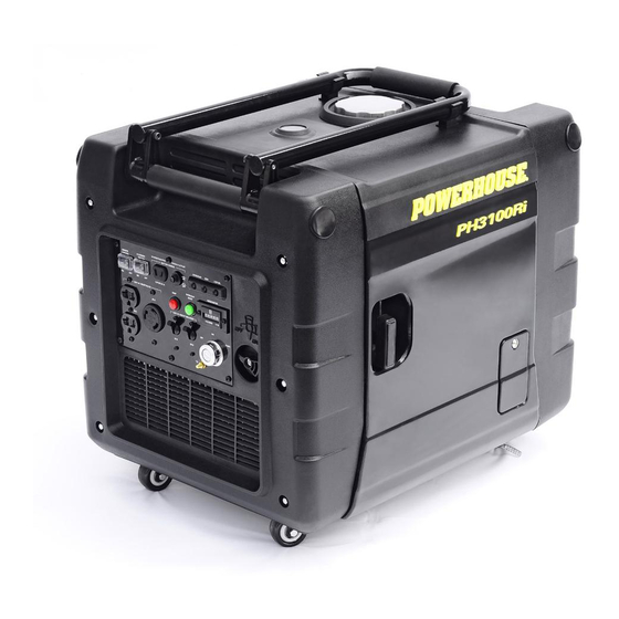
Page 9: Component Identification
2. COMPONENT IDENTIFICATION 2.1 PH3100Ri Generator Fold over handle Maintenance Cover Locking Wheels Fuel Cap Fuel Gauge Starter Grip Control Panel Engine Oil Access Cover Fuel Valve Swivel Wheels PH3100Pi OM... -
Page 10: Ph3100Ri Control Panel
2.2 PH3100Ri Control Panel Overload Light (red) 12 V DC - 8.3 A Run Light Battery Charge Battery Charge (green) Low Oil Light Receptacle Circuit Breaker (red) Remote Control Switch Remote Indicator Stop Button Light (Blinking) (Red) Hour Meter Economy... -
Page 11: Serial Number And Bar Code Identification And Location
Online registration will make sure you are protected in the event you have lost your receipt, and will significantly speed the process in the event warranty service is necessary. For warranty assistance: Phone: 877-544-4449 Fax: 800-263-0280 E-mail: warranty@powerhouse-products.com PH3100Pi OM... -
Page 12: Pre-Operation Check
Use a high-detergent, premium quality 4-stroke engine oil, certified to meet or exceed U.S. automobile manufacturer's requirements for API Service Classification SG/SF. Synthetic oil is approved for use in POWERHOUSE® generators, and is recommended for operating the generator in temperatures below 32° F. -
Page 13: Check The Fuel Level
3.2 Check the Fuel level Use automotive unleaded regular gasoline only. 1. If the fuel level is low, refill to the shoulder of the fuel strainer. 2. Never use an oil/gasoline mixture or dirty gasoline. 3. Avoid getting dirt, dust or water in the fuel tank. 4. -
Page 14: Check The Air Cleaner
3.3 Check the air cleaner 1. Loosen the cover screws and remove the maintenance cover. 2. Remove the air cleaner cartridge retaining screws. Remove the air cleaner cartridge and check the element. Clean or replace the element if necessary. 3. Replace the air cleaner element and cover. Tighten the screw securely. 4. -
Page 15: Connecting The Battery
3.4 Connecting the battery This generator ships with the internal battery disconnected, meaning you will have to connect the battery before you begin using the generator. 1. Loosen the cover screws and remove the maintenance cover. 2. Connect the quick connect cable to the battery wiring harness. 3. -
Page 16: Operating Instructions
4. OPERATING INSTRUCTIONS 4.1 Starting the engine The unit can be started by either the ignition key or remote. When the unit is started with the ignition key, it can be shut down by the ignition key or the Emergency shut-down button on the control panel;... -
Page 17: Manual Start
4.3 Manual Start 1. Turn the fuel valve lever to the “ON” position. 2. Move the remote selector switch to the “OFF” position. 3. Turn the ignition switch to the “ON” position. 4. Pull the starter grip lightly until resistance is felt, then pull briskly out. ... -
Page 18: High Altitudes
4.5 High Altitudes At high altitude, the standard carburetor air-fuel mixture will be excessively rich, performance will decrease, and fuel consumption will increase. High altitude performance can be improved by installing a smaller diameter main fuel jet in the carburetor. If you always operate the generator at altitudes higher than 5000 feet (1500 meters) above sea level, have your authorized dealer install a high altitude main jet. -
Page 19: Generator Use
4.7 Generator use Be sure to ground the generator when loads are connected. To prevent electrical shock from faulty appliances, the generator should be grounded. Connect a length of heavy cable between the generator's grounding terminal and an external ground source. ... -
Page 20: Ac Application
4.8 AC application 1. Start the engine and make sure the green run light comes on. 2. Confirm that the appliance to be used is switched off before plugging into the control panel. Run Light: The green run light indicates normal operating conditions. -
Page 21: Dc Application
4.10 DC Application You may use the DC receptacle to charge external batteries, to power DC devices, or to back-charge the internal generator battery with a battery charger. The DC receptacle provides a polarized, system floating 12V, 8.3A DC supply. The DC receptacle can be used to back-charge the generator whether the generator is running or not. - Page 22 The DC receptacle may be used while the AC power is in use. An overloaded DC circuit will trip the DC circuit breaker. If this happens reset the circuit breaker to resume operation. 4.10.2 Powering 12V DC devices This generator can be used to power 12V DC devices through the DC receptacle on the control panel while the generator is running.
-
Page 23: Low Oil Alarm System
4.11 Low Oil alarm system The low oil alarm system is designed to prevent engine damage caused by an insufficient amount of oil in the crankcase. Before the oil level in the crankcase falls below a safe limit, the low oil alarm system will automatically shut down the engine (the engine switch will remain in the “ON”... -
Page 24: Stopping The Engine
Stop 4.13 Stopping the engine To stop the engine in an emergency Stop 1. Push the STOP button on the control Ignition Button panel. This will stop the unit with or without the ignition key or remote. Normal shutdown 1. Turn off the connected equipment and disconnect from the generator. -
Page 25: Maintenance
Carbon monoxide is a poisonous gas. The emission of fuel vapors is a source of pollution as well. The POWERHOUSE® generator engine utilizes a precise air-fuel ratio and emission control system to reduce the emissions of carbon monoxide, , hydrocarbons, and evaporative fuel emissions. - Page 26 You can trust the replacement parts supplied by POWERHOUSE® have been manufactured to the same production standard as the original parts. The use of replacement parts or accessories which are not designed by POWERHOUSE® may affect the engine emission performance.
-
Page 27: Maintenance Schedule
5.2 Maintenance Schedule Regular Service period (1). Perform at every indicated month or operating hour interval, whichever occurs first. Maintenance Item Month Every 3 Months Every 6 Months 1x per Year Procedure Each Use 4 to 6 Hours 50 Hours 100 Hours 300 Hours Check... -
Page 28: Changing Oil
Recommended oil is SAE 15W-40 when ambient temperature is above 32° F (0° C). SAE 0W-40 is recommended if operating temperatures are below 32° F (0° C). Synthetic oil is approved for use in POWERHOUSE® generators, and is recommended for operating the generator in temperatures below 32° F. -
Page 29: Air Cleaner Service
5.4 Air cleaner service A dirty air cleaner will restrict air flow to the carburetor. To prevent carburetor malfunction, service the air cleaner regularly. Service more frequently when operating the generator in extremely dirty areas. Do not use gasoline or low flash point solvents for cleaning. They are flammable and explosive under certain conditions. -
Page 30: Spark Plug Service
5.5 Spark plug service Recommended spark plug: F7RTC To ensure proper engine operation, the spark plug must be properly gapped and free of deposits. 1. Loosen the cover screws and remove the maintenance cover. 2. Remove the spark plug cap. 3. -
Page 31: Spark Arrester Maintenance
5.6 Spark arrester maintenance If the generator has been running, the muffler will be very hot. Allow it to cool before proceeding. The spark arrester must be serviced every 100 hours to maintain its efficiency, or a decrease in horsepower may occur. ... -
Page 32: Transporting & Storage
6. TRANSPORTING & STORAGE 6.1 Transporting the Generator To prevent fuel spillage when transporting or during temporary storage, the generator should be secured upright in its normal operating position with the fuel valve, ignition switch and remote switch turned “OFF”. When transporting the generator: ... -
Page 33: Infrequent Use
6.3 Infrequent use Gasoline is extremely flammable and explosive under certain conditions. Do not smoke or allow flames or sparks in the area. During long-term storage, or infrequent use of your equipment, it is important to add a fuel stabilizer, such as Stabil®... -
Page 34: Troubleshooting
Take the generator to an Replace the authorized spark plug. Spark POWERHOUSE® dealer. Be sure there is no spilled fuel around the spark plug. Spilled fuel may ignite. To check spark: 1. Remove the spark plug cap and clean any dirt from around the spark plug. -
Page 35: Engine Will Not Crank With The Electric Or Remote Start
Charge or replace the battery. Is the battery dead? Check all electrical connections Take the generator to an authorized between battery, control panel and POWERHOUSE® service center. electric starter. 7.3 Appliance does not operate Is the circuit breaker “ON”? Reset the circuit... -
Page 36: No Output At The Dc Receptacle
7.4 No output at the DC receptacle Is the DC circuit breaker tripped? Reset the circuit breaker. Take the generator to an authorized POWERHOUSE® service center. PH3100Pi OM... -
Page 37: Specifications
8. SPECIFICATIONS Generator Model PH3100Ri Rated frequency (Hz) 60 Hz Rated voltage (V) 120 V Rated current (A) 25.0 A Max current (A) 25.8 A Rated output (W) 3000 W Max output (W) 3100 W DC Output 12 V, 8.3 A... -
Page 38: Tune Up Specifications
Tune Up Specifications Spark Plug Gap 0.028 - 0.031 in (0.7 - 0.8 mm) Valve Clearance (Intake) 0.0031 - 0.0039 in (0.08 - 0.10 mm) Valve Clearance (Exhaust) 0.004-0.006 in (0.10 - 0.15 mm) Dimensions Overall dimension H×W×D in (mm) 20.5"... -
Page 39: Warranty And Consumer Information
Proof of purchase and the serial number is required. Coverage Pre-approved parts and labor costs will be covered by POWERHOUSE® for any failure that is proven to be a failure in material or workmanship under normal use during the applicable warranty time period. This coverage is limited to parts, labor and ground shipping of repair parts. -
Page 40: California Emissions Control Warranty Statement
CALIFORNIA EMISSIONS CONTROL WARRANTY STATEMENT Your Warranty Rights and Obligations The California Air Resources Board and Coast Distribution System Inc. (POWERHOUSE®). are pleased to explain the emissions control system warranty on your 2008 and later small off-road engine (SORE). In California, new SOREs must be designed, built and equipped to meet the State's stringent anti-smog standards. -
Page 41: Emission Control System Warranty
EMISSION CONTROL SYSTEM WARRANTY Your POWERHOUSE® generator engine complies with U.S. Environmental Protection Agency, Environment of Canada, and the state of California (if the model is certified by CARB). The following systems and/or parts are covered by this warranty. Failures or improper operation of the following systems and components will be diagnosed and repaired with no charge for labor or parts. -
Page 42: Appendix A - Emission Control System
3. A catalyst is built into the muffler to further treat the engine exhaust. 4. A secondary air injection valve adds combustion air to ignite unburned fuel in the exhaust. Contact your authorized POWERHOUSE® service center to obtain the correct replacement parts and service on this system. -
Page 43: Appendix B - Safety And Charging Instructions
11. APPENDIX B - SAFETY AND CHARGING INSTRUCTIONS (a) SAVE THESE INSTRUCTIONS. THIS MANUAL CONTAINS IMPORTANT SAFETY AND OPERATING INSTRUCTIONS. (b) WORKING IN THE VICINITY OF A LEAD-ACID BATTERY IS DANGEROUS. BATTERIES GENERATE EXPLOSIVE GASES DURING NORMAL BATTERY OPERATION. FOR THIS REASON IT IS OF THE UTMOST IMPORTANCE THAT EACH TIME BEFORE USING YOUR CHARGER, YOU READ AND FOLLOW THE INSTRUCTIONS PROVIDED EXACTLY. - Page 44 FOR A NEGATIVE-GROUNDED VEHICLE, CONNECT THE POSITIVE (RED) CLIP FROM BATTERY CHARGER TO POSITIVE (POS, P, +) UNGROUNDED POST OF BATTERY. CONNECT THE NEGATIVE (BLACK) CLIP TO VEHICLE CHASSIS OR ENGINE BLOCK AWAY FROM BATTERY. DO NOT CONNECT CLIP TO CARBURETOR, FUEL LINES, OR SHEET-METAL BODY PARTS.
- Page 45 PH3100Pi OM...
- Page 46 DTS Manufacturing 7930 S.W. Burns Way, Unit C Wilsonville, OR 97070 www.powerhouse–products.com __________________________________________________ BCN # Label For This Unit __________________________________________________ Remote Serial Number Label This manual version applies to BCNs equal to or greater than: PH3100Ri OM (Revision – 2012-07-31) 120925401206001...
Need help?
Do you have a question about the PH3100Ri and is the answer not in the manual?
Questions and answers
What size socket for spark plug