
Related Manuals for Stelpro STE241


Summary of Contents for Stelpro STE241
- Page 1 User’s GUide sTe241 Low voLtage eLectronic thermostat (24v) For further information or to consult this guide online, please visit our website at www.stelpro.com INSSTE2410613...
- Page 2 warNiNG Before installing and operating this product, the owner and/or installer must read, understand and follow these instructions and keep them handy for future reference. If these instructions are not followed, the warranty will be considered null and void and the manufacturer deems no further responsibility for this product.
-
Page 3: Parts Supplied
DescriPtion The STE241 low voltage electronic thermostat (24 V) is designed to control relays (electronic or not). The allowed resistive maximum load is 12 W at 24 V (0.5 A). Then, relays (electronic or not) connected to the thermostat can control electric baseboards with or without fans, convectors, fan heaters and electric furnaces. -
Page 4: Thermostat Mounting And Connection
thermostat mounting and connection 1. Ensure that the air vents of the thermostat are clean and clear of any obstruction. 2. Using a screwdriver, loosen the screw retaining the mounting base and front part of the thermostat. Remove the front part of the thermostat from the mounting base by tilting it upward. - Page 5 4. Connect the wires coming from the 24 VAC power source following the appropriate diagram below: cONNecTiON examPle #1 One baseboard with a STELPRO RE-153T electronic relay with a 24 VAC transformer. ELECTRIC RELAY WITH TRANSFORMER BLACK BLACK BLUE WHITE...
- Page 6 cONNecTiON examPle #3 Standard 24 VAC power source (24 VAC transformer) TRANSFORMER CONTACTOR 24 VAC OR RELAY NOTE: the color of the wires can change according to the electronic relays that are used. Connection diagrams in this guide are only examples. 5.
-
Page 7: Operation
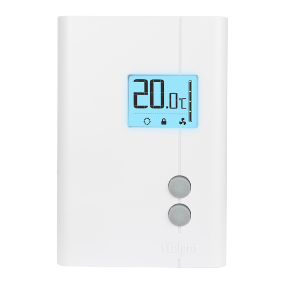
oPeration Ambient temperature timer Heating power used indicator Pictograms Fan mode Frost-free Smart mode warning Mode Sécurité Day mode Night mode Top button Bottom button Powering on for the first time When powering on for the first time, the thermostat is initially set to ‘Day’ mode. - Page 8 Day mode and night mode The thermostat includes a Day mode and a Night mode, both of them having their own independently adjustable and recorded set point. When switching from one mode to the other, the system will automatically use the temperature set point corresponding to the Day/Night mode selected.
-
Page 9: Smart Mode
N.B. The Night mode timer will be automatically reinitialized to the latest recorded value when switching from the Day mode to the Night mode. It is not necessary to readjust the timer every time you switch to the Night mode. The timer is also reinitialized when this value is adjusted. - Page 10 3. Activate the Smart mode by simultaneously pressing down the two buttons for at least 3 seconds. The icon will appear. If the Smart mode was already activated, the same procedure should be used to deactivate it. 4. When the adjustment is completed, release the buttons and wait for 5 seconds to exit the adjustment function.
-
Page 11: Security Mode
Minimum ON/OFF time selection in Long cycle In Long cycle, you can adjust the minimum ON/OFF time (e.g. the minimum time between the start and the shut down of the heating). First, activate the Long/Short cycle mode as described in the previous section. Press down the bottom button for 3 seconds until the time in seconds appears on the screen. -
Page 12: Fan Mode
Procedures to deactivate the security mode 1. To deactivate Security mode, start by cutting thermostat power at circuit breaker and wait at least 20 seconds. 2. Turn thermostat power back on and the icon will blink for a maximum of 5 minutes. 3. - Page 13 Please note that the Smart mode is not automatically reactivated when thermostat is turned on. The icon blinks to warn the user that the mode was previously activated when thermostat was shut off but is no longer active. Furthermore, when power is shut off, the existing Day/Night mode is recovered only if the Smart mode was previously deactivated.
-
Page 14: Troubleshooting
troubLeshooting DeFeCTIVe PArT or PArT Problem To CHeCK • Check if the thermostat is Heating is always on properly connected. Refer to the installation section. • Check if the thermostat is Heating does not run even if the properly connected. Refer to thermostat indicates it is on the installation section. -
Page 15: Technical Specifications
• Possibility of a bad contact. Weak luminosity of the display Check thermostat wirings. Refer to the installation section. If you are unable to solve the problem after having verified these points, please communicate with our customer service. Consult our website for the phone numbers. -
Page 16: Limited Warranty
The warranty is limited to the factory repair or the replacement of the unit, and does not cover the cost of disconnection, transport, and installation. E-mail: contact@stelpro.com Web site: www.stelpro.com STelPrO DeSigN iNc. | Saint-Bruno-de-montarville | Quebec | J3V 6l7 INSSTE2410613...
Need help?
Do you have a question about the STE241 and is the answer not in the manual?
Questions and answers