
Related Manuals for Stelpro STE362RNP


Summary of Contents for Stelpro STE362RNP
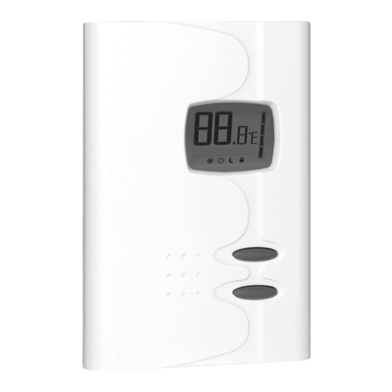
- Page 1 User’s Guide “STE362RNP” Electronic thermostat For further information or to consult this guide on line, please visit our Web site. INSSTE362RNP0609...
- Page 2 WARNING WARNING Before installing and operating this product, the owner and/or installer must read, understand and follow these instructions and keep them handy for future reference. If these instructions are not followed, the warranty will be consid- ered null and void and the manufacturer deems no further responsibility for this product.
- Page 3 1. Description The electronic thermostat STE362RNP can be used to con- trol electric heating units such as electric baseboards, con- vectors, or aeroconvectors. It keeps the temperature of a room at the requested set point with a high degree of ac- curacy.
-
Page 4: Installation
2. Installation Selection of thermostat location The thermostat must be mounted on a connection box on a wall facing the heating unit, at around 1.5 m (5 feet) above the floor level, on a section of the wall exempt from pipes or air ducts. -
Page 5: Thermostat Mounting And Connection
Thermostat mounting and connection Cut off power supply on lead wires at the elec- trical panel in order to avoid any risk of electric shock. 2. Ensure that the air vents of the thermostat are clean and clear of any obstruction. 3. - Page 6 5. Take the wires from the wall through the hole at the base of the thermostat and connect them using the supplied solderless connectors. When making the connection with aluminum wire, make sure that you are using connectors identified CO/ALR. Please note that the thermostat wires do not have polarity.
-
Page 7: Operation
3. Operation ambient temperature/ timer heating power used indicator pictograms fan mode automatic mode frost-free warning day mode lock mode night mode top button bottom button Powering on for the first time When powering on for the first time, the thermostat is initially set to ‘Day’... - Page 8 The set point value displayed will be OFF, and heating system start up will be impossible. Day mode and Night mode The thermostat includes a Day mode and a Night mode, both of them having their own independently adjustable and recorded set point.
-
Page 9: Automatic Mode
Night mode timer adjustment procedure 1. If necessary, adjust the Day/Night mode set points at the desired temperatures. If needed, switch from one mode to the other by simultaneously pressing down the two but- tons and releasing them immediately. 2. From the Night mode, simultaneously press down the two buttons for more than 3 seconds until the moon icon blink- ing and the letter H appear. - Page 10 For example, if the Automatic mode is activated and the Night mode timer is set at 8 hours, the thermostat will be op- erating in the Night mode for 8 hours at the night temperature set point. Then, it will return to the Day mode for 16 hours operating at the day temperature set point.
- Page 11 3. Activate the Automatic mode by simultaneously pressing down the two buttons for at least 3 seconds. The Auto- matic mode icon will appear. If the Automatic mode was already activated, the same procedure should be used to deactivate it. 4.
-
Page 12: Temperature Control
Display in Degrees Celsius/Fahrenheit The thermostat can display the ambient temperature and the set point in degrees Celsius (standard factory setting) or Fahrenheit. Selection procedure for degree Celsius/Fahrenheit dis- play. 1. From the Day mode, simultaneously press down the two buttons for more than 3 seconds. - Page 13 Programmable Heating Cycle This setting allows the length of a heating cycle to be adjust- ed. To activate this programmable heating cycle setting, the thermostat should be in day mode and the user must press on the two buttons for 20 seconds. Note that the pictogram displaying the degrees (C or F) will flash after three seconds, will stop flashing after 13 seconds and a padlock will appear or disappear depending on the setting (the thermostat lock...
-
Page 14: Lock Option
Lock option It is possible to impose a maximum temperature set point by activating this mode. Then, it becomes impossible to exceed this set point, regardless of the current mode (Day/ Night). However, it is still possible to lower the set point at your discretion. -
Page 15: Fan Mode
Fan mode The activation of the fan mode is similar to the Celsius/Fahr- enheit adjustment. To activate or deactivate fan mode, you must press both buttons simultaneously for at least 3 sec- onds while in day mode. Once the 3 seconds have passed, C or F will flash. - Page 16 Please note that the automatization of the day/night modes is not automatically reactivated when thermostat is turned on. The icon for the automatization of the day/night modes flash- es to warn the user that the mode was previously activated when thermostat was shut off but is no longer active. Furthermore, when power is shut off, the existing Day/Night mode is recovered only if the automatization of the day/night modes was previously deactivated.
-
Page 17: Troubleshooting
4. Troubleshooting Problem Solution In normal operating conditions, the thermostat housing can reach nearly The thermostat is hot. 40°C at maximum load. That is normal and will not affect the effective operation of the thermostat. Check if the thermostat is Heating is always on. - Page 18 The display indicates Faulty thermal sensor. Contact E1 or E2. the customer service. Possibility of a bad contact. Weak luminosity of the Check thermostat wirings. display. Refer to the installation section. N.B. If you are unable to solve the problem after having veri- fied these points, please communicate with our custom- er service.
-
Page 19: Technical Specifications
5. Technical Specifications Supply voltage: 120/208/240 VAC, 50/60 Hz Maximum electrical current with a resistive load: 15 A 3600 W @ 240 VAC 3120 W @ 208 VAC 1800 W @ 120 VAC Temperature display range: 3°C to 40°C (37°F to 99.5°F) Temperature display resolution: 0.5°C (0.5°F) Temperature set point range:... -
Page 20: Limited Warranty
The warranty is limited to the factory repair or the replacement of the unit, and does not cover the cost of discon- nection, transport, and installation. Customer service Stelpro Design inc. 1041, Parent Street St-Bruno (Quebec) Canada J3V 6L7 Email: contact@stelpro.com Web site: www.stelpro.com...
Need help?
Do you have a question about the STE362RNP and is the answer not in the manual?
Questions and answers