
Related Manuals for Stelpro STE302R2+


Summary of Contents for Stelpro STE302R2+
- Page 1 User’s Guide “STE302R2+” Electronic thermostat For further information or to consult this guide online, please visit our Web site. INSSTE302R2+0711...
- Page 2 WARNING WARNING Before installing and operating this product, the owner and/or installer must read, understand and follow these instructions and keep them handy for future reference. If these instructions are not followed, the warranty will be considered null and void and the manufacturer deems no further responsibility for this product.
- Page 3 1. Description The STE302R2+ non programmable electronic thermostat can be used to control electric heating units such as electric baseboards, convectors, or aeroconvectors. It keeps the temperature of a room at the requested set point with a high degree of accuracy. This product is designed for installations with electrical current - with a resistive load - ranging from 0 A to 12,5 A (120/208/240 VAC).
-
Page 4: Installation
2. Installation Selection of thermostat location The thermostat must be mounted on a connection box on a wall facing the heating unit, at around 1.5 m (5 feet) above the floor level, on a section of the wall exempt from pipes or air ducts. -
Page 5: Thermostat Mounting And Connection
Thermostat mounting and connection Cut off power supply on lead wires at the electrical panel in order to avoid any risk of electric shock. 2. Ensure that the air vents of the thermostat are clean and clear of any obstruction. 3. - Page 6 5. Take the wires from the wall through the hole at the base of the thermostat and connect them using the supplied solderless connectors. When making the connection with aluminum wire, make sure that you are using connectors identified CO/ALR. Please note that the thermostat wires do not have polarity.
-
Page 7: Operation
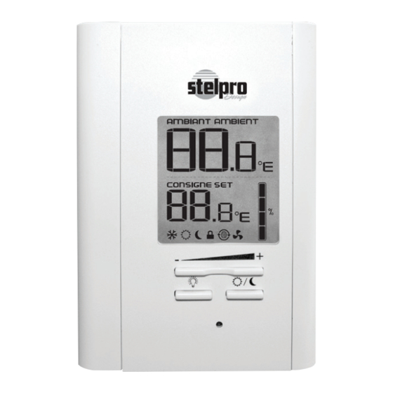
3. Operation Ambient temperature/ Timer Heating power used indicator Pictograms Fan mode Frost-free warning Day mode Smart mode Night mode Security mode Button (-) Button (+) Backlit button Day/Night button Powering on for the first time When powering on for the first time, the thermostat is initially set to Day mode. -
Page 8: Backlit Screen
Backlit screen The backlight screen lights up when you press down a button. If you do not press down any button during 15 seconds, the blacklight screen will turn off. It is possible to turn on the backlit screen without modifying anything by pressing down the (+) or (-) button once or by pressing down the Sun or Moon button when the backlit screen is off. - Page 9 Day mode and Night mode The thermostat includes a Day mode (Sun) and a Night mode (Moon), both of them having their own independently adjustable and recorded set point. The ambient temperature is displayed above the set point, in degrees Celcius or Fahrenheit.
- Page 10 Night mode timer adjustment procedure 1. First, switch to the Night mode by pressing down the Day/ Night button and releasing it immediately (press it down twice if the backlit screen is off and once if the backlit screen is on). 2.
- Page 11 Smart mode The Smart mode, which is associated to the Night mode timer, allows alternating between the Day/Night modes and the two corresponding set points over a 24-hour period. Once activated, this mode allows an automatic return to the Night mode after 24 hours. The Smart mode allows you to define two periods in a single day with different set points.
- Page 12 instead of the three figures at the bottom of the screen. Then, you can release the buttons. 3. Activate the Smart mode by simultaneously pressing down the (+) and (-) buttons for at least 3 seconds. The icon will appear. If the Smart mode was already activated, the same procedure should be used to deactivate it.
-
Page 13: Temperature Control
Display in degrees Celsius/Fahrenheit The thermostat can display the ambient temperature and the set point in degrees Celsius (standard factory setting) or Fahrenheit. Selection procedure for degrees Celsius/Fahrenheit display. 1. From the Day mode, simultaneously press down the (+) and (-) buttons for more than 3 seconds. - Page 14 Programmable heating cycle This setting allows the length of a heating cycle to be adjusted. To activate this programmable heating cycle setting, the thermostat should be in Day mode and the user must press and hold down the (+) and (-) buttons for 20 seconds. Note that the SET icon will blink after 3 ...
- Page 15 Security mode It is possible to impose a maximum temperature set point by activating this mode. Then, it becomes impossible to exceed this set point, regardless of the current mode. However, it is still possible to lower the set point at your discretion. Procedures to activate the Security mode 1.
-
Page 16: Fan Mode
Fan mode The activation of the Fan mode is similar to the Celsius/ Fahrenheit adjustment. To activate or deactivate the Fan mode, you must press down the (+) and (-) buttons simultaneously for at least 3 seconds while in Day mode. Once the 3 ... - Page 17 Parameters saving and power failures The thermostat saves some parameters in a non-volatile memory to be able to recover them after being shut off (a power failure, for example). These parameters are the Day/ Night settings, the Smart mode, the state of the Security mode, the maximum setting of the Security mode, the Celsius/Fahrenheit mode, the number of hours on the night time-switch, the language, Fan mode, the number of minutes...
-
Page 18: Troubleshooting
4. Troubleshooting Problem Solution In normal operating conditions, the thermostat housing can reach nearly The thermostat is hot. 40°C at maximum load. That is normal and will not affect the effective operation of the thermostat. Check if the thermostat is Heating is always on. -
Page 19: Technical Specifications
5. Technical specifications Supply voltage: 120/208/240 VAC, 50/60 Hz Maximum electrical current with a resistive load: 12,5 A 3000 W @ 240 VAC 2600 W @ 208 VAC 1500 W @ 120 VAC Temperature display range: 3°C to 40°C (37°F to 99.5°F) Temperature display resolution: 0.5°C (0.5°F) Temperature set point range:... -
Page 20: Limited Warranty
The warranty is limited to the factory repair or the replacement of the unit, and does not cover the cost of discon- nection, transport, and installation. Customer service Stelpro Design inc. 1041, Parent Street Saint-Bruno-de-Montarville (Quebec) Canada J3V 6L7 E-mail: contact@stelpro.com Web site: www.stelpro.com...
Need help?
Do you have a question about the STE302R2+ and is the answer not in the manual?
Questions and answers