
Related Manuals for Godex EZ2050


Summary of Contents for Godex EZ2050
- Page 1 EZ2050/EZ2150 BARCODE PRINTER USER MANUAL User Manual : EZ2050 series Version : Rev. D Issue Date : 2013.07.18 : 920-014411-00...
-
Page 2: Table Of Contents
EZ2050/EZ2150 USER MANUAL CONTENTS 1. BARCODE PRINTER ..............1 1-1. Box content ..................... 1 1-2. Getting to know your printer ..............2 2. PRINTER SETUP ................4 2-1. Loading the label roll ................4 2-2. Loading the ribbon ................. 7 2-3. - Page 3 EZ2050/EZ2150 USER MANUAL FCC COMPLIANCE STATEMENT FOR AMERICAN USERS This equipment has been tested and found to comply with the limits for a CLASS A digital device, pursuant to Part 15 of the FCC Rules. These limits are designed to provide reasonable protection against harmful interference when the equipment is operated in a commercial environment.
-
Page 4: Safety Instructions
EZ2050/EZ2150 USER MANUAL SAFETY INSTRUCTIONS Please read the following instructions carefully. Keep the equipment away from humidity. Before you connect the equipment to the power outlet, please check the voltage of the power source. Make sure the printer is off before plugging the power connector into the power jack. -
Page 5: Barcode Printer
Barcode Printer Box Content Please check that all of the following items are included with your printer. EZ2050/EZ2150 Barcode Printer Label Stock USB Cable EZ2050 Series Quick Guide Ribbon Module Power Adapter Empty Ribbon Core Power Cord ... -
Page 6: Getting To Know Your Printer
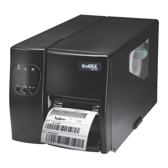
Barcode Printer Getting to Know Your Printer External view Operator panel Lower cover plate Viewing window Printer cover Feed slot for continuous labels Auto-Calibration button Parallel port (optional) Applicator interface (optional) N Ethernet port USB port Serial port (DB-9) On/Off switch Power jack Feed slot for continuous labels... - Page 7 Barcode Printer Ribbon rewind hub Ribbon supply hub Print mechanism Platen roller Tear-off plate Release lever for print head Adjustment wheel for sensor Paper guide Label tension guide Label supply hub Label roll guide Release catch Movable sensor...
-
Page 8: Printer Setup
Printer Setup Loading the label roll This printer supports the following printing methods: Thermal transfer printing (TTP):Requires a ribbon for transferring a printed image to a medium. Direct thermal printing (DTP):Does not require a ribbon, only thermal paper. Please check which printing method you are using and alter the settings accordingly in the printer driver, printer menu, and/or software. - Page 9 Printer Setup Place the label roll on the label supply hub, pushing it right up to the printer housing. (Do not apply too much pressure to avoid damaging the label stock.) Fold the label roll guide back down and push it against the label roll. 【...
- Page 10 Printer Setup The labels pass between the wall of the printer housing and the adjustable paper guide. Note 【 】 Pass the labels through the printer as shown in the illustration. 10. Return the print head release lever to its original position. 11.
-
Page 11: Loading The Ribbon
Printer Setup Loading the Ribbon 1. Place the printer on a flat surface and open the printer cover. 2. Pull out the print head release lever as shown in the illustration (1) and turn it anticlockwise to a top right position (2). -
Page 12: Connecting The Printer To The Host Computer
Printer Setup Connecting the Printer to the Host Computer Please make sure that the printer is switched off. Connect the power cord to the AC adapter and connect the adapter to the printer. Connect the USB cable to the printer and host computer. Switch on the printer. - Page 13 Insert the product CD in the CD/DVD drive of the host computer and open the "Seagull Drivers" folder on the CD. Select the icon for the driver file and click it to start the installation. Follow the instructions on the screen. The Driver Wizard guides you through the installation procedure. Select "Install printer drivers". Specify your printer model. Godex EZ2050...
- Page 14 Printer Setup Specify the port used to connect the printer to the host computer. Enter a printer name and assign the appropriate rights. Godex EZ2050 Godex EZ2050 Once the installation is complete, a summary of the printer settings is displayed.
- Page 15 Printer Setup Once the driver installation is complete, the new printer should appear in the "Printers and Faxes" folder. Godex EZ2050 Godex EZ2050...
-
Page 16: Operation Panel
Printer Setting and Control Operation Panel Operation Panel Introduction Function buttons FEED PAUSE CANCEL LED indicators The POWER (Ready) LED lights up when the printer POWER has started up and is ready to print. (1) Ribbon status indicator RIBBON / (2) Density adjustment DENSITY indicator in Setting... -
Page 17: Function Buttons - Introduction
Setting and Control for Operation Panel Function buttons – introduction FEED button When you press the FEED button, the printer moves the label to the defined stop position. If you are using continuous labels, pressing the FEED button will move label stock until you release the button again. -
Page 18: Settings Mode
Setting and Control for Operation Panel Settings mode In settings mode, you can change different settings, such as the printing mode or media type. Switch on the printer and make sure that the POWER (Ready) LED lights up. Press the PAUSE button and keep it pressed for about 3-4 seconds until you hear 3 beeps. - Page 19 Setting and Control for Operation Panel When reaching this item, press button to set the Direct printer to TT mode, press Thermal / button to set the Thermal mode mode printer to DT mode and Transfer press button to go to next item.
-
Page 20: Label Calibration And Self Test
The printer will now measure the label stock and store the label height. Once the printer has successfully measured the label stock, it will print a self-test label. The contents of a self-test printout are listed below. EZ2050:GX.XXX Model & Version USB S/N:12345678... - Page 21 Setting and Control for Operation Panel Label Calibration Button A hardware button to make a Label Calibration while printer encountering ‘’Media Error’’ during the cases when first-time printer start up or change label or ribbon to another type, such as change using gap label to continuous or black mark labels.
-
Page 22: Dump Mode
Setting and Control for Operation Panel Dump mode If the label settings do not match the printer output, you can switch the printer to dump mode to check whether an error has occurred during the transfer between printer and host computer. In dump mode, the unprocessed raw data are sent to the printer and printed. -
Page 23: Error Alerts
Setting and Control for Operation Panel Error alerts In the event of a problem that prevents normal functioning of the printer, you will see an error message on the display and hear some beep signals. The LED indicators will also light up. -
Page 24: Accessories
Accessories Internal rewinder Rewinder Retention clip Screws (set of 4) Rewinder guide 【 Note 】 Maximum height of the rewound medium: 118 mm Suggestion 【 】 Medium thickness: 0.06 mm– 0.25 mm Place the printer on a flat surface and open the printer cover. - Page 25 Accessories Remove the retention clip from the rewinder. Secure the rewinder on the printer housing using the four screws supplied. Now connect the rewinder cable to the printer housing. Installation of the rewinder module is now complete.
-
Page 26: Installing The Rewinder Guide
Accessories Installing the rewinder guide Unscrew the screw marked in the illustration on the front of the printer, which secures the lower cover plate. Remove the lower cover plate. Note 【 】 Switch off the printer before starting the installation. Mount the rewinder guide on the print mechanism and secure it with screws. -
Page 27: Label Dispenser
Accessories Label dispenser Wind the label liner around the rewinder and secure it using the retention clip. Return the print head release lever to its original position. 【 Note 】 Please make sure that the label stock rewinds the right way onto the rewind hub. - Page 28 Accessories Wind the label liner around the rewinder and secure it using the retention clip. Return the print head release lever to its original position. 【 Note 】 Please make sure that the label stock rewinds the right way onto the rewind hub. 10.
-
Page 29: Installing The Cutter
Accessories Installing the cutter Cutter cover Cutter module Cable clips Screws (set of 4) 【 Note 1 】 Remember to switch off the printer before installing the cutter. Note 2 【 】 Do not use to cut adhesive labels! Glue residue will be left on the cutter blade and impair its functioning. - Page 30 Accessories Secure the cutter module on the printer housing using the screws. Connect the cutter cable connector to the cutter jack on the printer. Route the connection cable along the bottom of the printer housing using the cable clips. Place the cutter cover over the cutter module and secure it using the screw you removed from the lower...
-
Page 31: Installing The Parallel Adapter
Accessories Installing the Parallel adapter Parallel cable Parallel adapter Connection cable Screws (set of 2) Check whether the printer is switched off. Place the printer on a flat surface and open the printer cover. Unscrew the two screws marked in the illustration on the right and remove the left-hand side of the printer housing. - Page 32 Accessories Install the Parallel adapter in its place and secure it on the housing with screws. Connect the 30-pin connection cable to the motherboard. Replace the left-hand part of the printer housing and secure it with the screws you removed earlier. Installation of the Parallel adapter is now complete.
-
Page 33: Installing The Applicator Interface
Accessories Installing the Applicator interface Applicator interface Screws (set of 2) Place the printer on a flat surface and open the printer cover. 【 Note 】 Remember to switch off the printer before starting the installation. Unscrew the two screws marked in the illustration on the right and remove the left-hand side of the... - Page 34 Accessories Pass the applicator cable through the opening into the housing. Connect the applicator cable to the jack marked "APP" on the motherboard. Secure the applicator interface using two screws. Replace the left-hand part of the printer housing and secure it with the screws you removed earlier to complete the...
-
Page 35: Maintenance And Adjustment
Maintenance and Adjustment Installing / removing the print head module Open the printer cover. 【 Note 】 Remember to switch off the printer before removing the print head module. Pull out the print head release lever as shown in the illustration (1) and turn it anticlockwise to a top right position (2). -
Page 36: Adjusting The Print Line
Maintenance and Adjustment Adjusting the print line Please contact your local dealer for technical support. Open the printer cover. Pull out the print head release lever as shown in the illustration (1) and turn it anticlockwise to a top right position (2). - Page 37 Maintenance and Adjustment Adjusting the print line You can adjust the ribbon tension by turning the ribbon shaft knob (green wheel at the base of the ribbon supply hub – see illustration) clockwise or anticlockwise. There are 4 possible settings, which are marked on the knob of the ribbon rewind hub and the ribbon supply hub.
-
Page 38: Cleaning The Thermal Print Head
Maintenance and Adjustment Cleaning the thermal print head Dirt on the print head or ribbon may result in inadequate print quality (no printed image on part of the label). The printer cover should therefore be kept closed whenever possible. Keeping dirt and dust away from the paper or labels ensures a good print quality and a longer lifespan of the print head. -
Page 39: Adjusting The Balance And Print Head Tension
Maintenance and Adjustment Adjusting the balance and print head tension Open the printer side cover. Pull out the print head release lever as shown in the illustration (1) and turn it anticlockwise to a top right position (2). When using a variety of label stock and ribbons, the ink may not be evenly distributed. -
Page 40: Ribbon Shield Settings
Maintenance and Adjustment Ribbon shield settings The use of different ribbon materials may cause wrinkling of the ribbon, which in turn affects the print result as illustrated by the examples in (a) and (b). To change the print quality, you can adjust the ribbon shield screws. If your print result looks like the example in (a), you need to turn ribbon shield screw A clockwise. -
Page 41: Cutter Settings
Maintenance and Adjustment Cutter settings Socket head screws for adjusting the cutter are located on both sides of the cutter. In the event of a paper jam, the cutter will no longer function correctly. Switch off the printer and use a hex key (#M3) to turn the socket head screw. -
Page 42: Troubleshooting
Maintenance and Adjustment Troubleshooting Problem Solution ♦ Check the power supply. The printer is switched on but the LED does not light up. Please see the Section 2.4 Check the software settings (driver settings) or command codes. ♦ Look for the error alert in the table in Section 3.3. Error Alerts. ♦... -
Page 43: Appendix
* **Minimum print height and maximum print speed specification compliance can be dependent on non-standard material variables such as label type, thickness, spacing, liner construction, etc. Godex is pleased to test non-standard materials for minimum print height and maximum print speed capability. - Page 44 EZ2050/EZ2150 USER MANUAL APPENDIX INTERFACE Parallel port Handshaking : DSTB is sent to the printer, BUSY to the host computer Interface : Parallel cable compatible with IBM computers cable Pinout : See below Pin No. Function Transmitter /Strobe Computer / printer...
- Page 45 EZ2050/EZ2150 USER MANUAL APPENDIX INTERFACE Connector Type : Type B Pin NO. Function VBUS Internal interface UART1 wafer Ethernet module E_MD E_MD E_RST E_RST UART2 wafer Add-on module Appendix Appendix...
- Page 46 EZ2050/EZ2150 USER MANUAL APPENDIX INTERFACE Applicator wafer Applicator module +24V +24V Printing (out) Printing Print error (out) Print error Printed (out) Printed Print (in) Print Appendix Appendix...
Need help?
Do you have a question about the EZ2050 and is the answer not in the manual?
Questions and answers