
Subscribe to Our Youtube Channel
Related Manuals for Godex BP500L


Summary of Contents for Godex BP500L
- Page 1 USER MANUAL BP500L SERIES Version : Rev.B Issue Date : 2018.02.13 : 920-016411-00...
-
Page 2: Table Of Contents
CONTENTS Barcode Printer ....................................1 1-1 Box Content ....................................1 1-2 Getting To Know Your Printer ..............................2 Printer Setup ...................................... 4 2-1 Open The Printer Cover ................................4 2-2 Open The Printing Mechanism ..............................5 2-3 Loading The Ribbon ..................................6 2-4 Loading The Label Roll ................................ -
Page 3: Fcc Compliance Statement
EN55024:2010+A1:2015, IEC 60950-1(ed.2), IEC 60950-1(ed.2);am1, IEC 60950- 1(ed.2);am2 series The equipment also tested and passed in accordance with the European Standard EN55032 for the both Radiated and Conducted emissions limits. BP500L Series TO WHICH THIS DECLARATION RELATES IS IN CONFORMITY WITH THE FOLLOWING STANDARDS IEC 60950-1(ed.2), IEC 60950-1(ed.2);am1, IEC 60950- 1(ed.2);am2, GB9254-2008 (Class A ) ;... - Page 4 SAFETY INSTRUCTIONS Please read the following instructions carefully. Keep the equipment away from humidity. Before you connect the equipment to the power outlet, please check the voltage of the power source. Make sure the printer is off before plugging the power connector into the power jack.
-
Page 5: Barcode Printer
Barcode Printer Box Content Please check that all of the following items are included with your printer. (Package content and Logo style may vary per region。) Barcode Printer Ribbon Hubs ( set of 2 ) Empty Ribbon Core Power Cord USB Cable ... -
Page 6: Getting To Know Your Printer
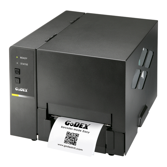
1-2 Getting To Know Your Printer Front View TOP COVER LED INDICATOR VIEWING WINDOW 之 POWER BUTTON FEED BUTTON FRONT COVER Rear View AUTO-CALIBRATION BUTTON USB PORT EXTERNAL LABEL INSERT POWER JACK FAN-FOLD LABEL INSERT 之... - Page 7 Open The Printer Cover LABEL SUPPLY MODULE - LABEL SUPPLY HUB - LABEL GUIDE PLATES RIBBON FEED MECHANISM RIBBON HUB EMPTY RIBBON CORE ADJUSTMENT SCREW ( LEFT ) ADJUSTMENT SCREW ( RIGHT ) Screw for adjusting the print head pressure Screw for adjusting the print head pressure ...
-
Page 8: Printer Setup
Printer Setup 2-1 Open The Printer Cover Pressing The Cover Open Buttons Place the printer on a flat surface. Open the printer cover by pressing the release buttons on both sides of the printer housing and lift the cover. -
Page 9: Open The Printing Mechanism
2-2 Open The Printing Mechanism Pressing The Release Catches Release and lift the printing mechanism. RELEASE CATCH (LEFT) Lift the printing mechanism RELEASE CATCH (RIGHT) Pressing Pressing... -
Page 10: Loading The Ribbon
2-3 Loading The Ribbon A New Ribbon Module Installation Place the new ribbon on the hub which forms a ribbon supply hub. Place on the hub RIBBON SUPPLY HUB RIBBON HUB NEW RIBBON Place the empty ribbon core on the hub which forms a ribbon rewind hub. Place on the hub RIBBON FEED MODULE RIBBON HUB... - Page 11 Install The Ribbon On The Printer Place the ribbon supply hub at the back of the printing mechanism. Insert into the printing mechanism Pass the ribbon supply hub under the print head. Insert the ribbon rewind hub on the ribbon feed mechanism. Close the printing mechanism, making sure that it clicks into place Place on the printing mechanism...
-
Page 12: Loading The Label Roll
2-4 Loading The Label Roll A New Label Roll Module Installation Place the label stock on the label supply hub, attach the guide plates to the label stock holder. LABEL STOCK Place on the ribbon hub LABEL SUPPLY HUB LABEL GUIDE PLATES ... - Page 13 Step.02 Close the printing mechanism. Close the printing mechanism Step.03 Install The Label Roll Module On The Printer Place the label stock into into the printer as the direction of the arrows.
-
Page 14: Installing The Label Supply Hub
2-5 Installing The Label Supply Hub 1" Cores Installing the label supply hub for 1" cores. 1.5" Cores Installing the label supply hub for 1.5" cores. -
Page 15: Preparing For Tag Printing
2-6 Preparing For Tag Printing In tag printing, the tag hole indicates the height of a label. During adjustment, the sensor must therefore be positioned directly below the tag hole as shown in the illustration. The tag hole should be at least 3 mm in diameter to ensure correct functioning. SENSOR POSITION... -
Page 16: Installation Of External Label Roll And Fanfold Label Roll
2-7 Installation of External Label Roll and Fanfold Label Roll EXTERNAL LABEL INSERT FAN-FOLD LABEL INSERT Installation of External Label Roll Installation of Fanfold Label Roll... -
Page 17: Connecting The Printer To The Host Computer
2-8 Connecting The Printer To The Host Computer Please make sure that the printer is switched off. Connect the power cord to the AC adapter and connect the adapter to the printer. Connect the USB / parallel cable to the printer and host computer. (The type of cable may vary according to the products which you purchase.) ... -
Page 18: Wizard Cd Standard Installation
2-9 Wizard CD Standard Installation Step.01 Insert the Super Wizard CD in the CD/DVD drive of the host computer and the installation program should pop up automatically. You will see the Welcome screen first. On the Welcome screen, choose “STANDARD INSTALLATION”. Step.02 The wizard will then ask you to make sure your USB and power cables are connected and that the power is turned on. - Page 19 Step.04 As the printer driver and GoLabel are installing, a screen will display a progress bar. While downloading completed you will see Installation completed. Click “NEXT” to continue. You can also print a test label. If don’t print a test label, the screen display as step 6. Step.05 Note * If you need more resources, tools or reference documents, you can also find them on Super Wizard CD.
- Page 20 Step.06 Once the installation is complete, you can start to make and print labels with GoLabel or through the printer driver.
-
Page 21: Wizard Cd Other Choice Installation
2-10 Wizard CD Other Choice Installation Click “OTHER CHOICES” to next screen and select “PRINTER DRIVERS”. Step.01 Click “INSTALL SEAGULL SCIENTIFIC WINDOWS DRIVER” to next screen, and click “NEXT”. Step.02 Select “I accept the terms in the license agreement”, and click ”Next”,then click ”Finish” to step 4. Step.03... - Page 22 Step.04 The Driver Wizard will guide you through the installation procedure. Select "Install printer drivers" and click “Next”. Step.05 With a USB connection, search models such as the right diagram printer device. Specify your printer model and click ”Next”. Step.06 Enter the printer name (you can use default), then click "Next"...
- Page 23 Step.07 Driver installation completed.
-
Page 24: Operation Panel
Operation Panel 3-1 LED Operation Panel FEED Button When you press the FEED button, the printer moves the label to the defined stop position. If you are using continuous labels, pressing the FEED button will move label stock until you release the button again. If you are using individual labels, pressing the FEED button will move only one label. -
Page 25: Label Size Calibration And Self Test Page
3-2 Label size calibration and Self Test Page The printer can automatically detect and store label height. That means the host computer does not need to transmit the label height to the printer. And the self-test function lets you check whether the printer is functioning normally. Here is how you run the label size calibration and self test. -
Page 26: Error Alerts
3-3 Error Alerts In the event of a problem that prevents normal functioning of the printer, you will see an error message on LED indicators and hear some beep signals. Please refer to below table for the error alerts. Light on ... -
Page 27: Netsetting For Ethernet
NetSetting for Ethernet 4-1 Installing the NetSetting software The NetSetting software is used to manage the network configurations when connecting the printer via Ethernet port. It is available on product CD or can be downloaded from official website. To install the NetSetting, please follow below steps. - Page 28 Step.05 Once the installation is completed, you will see the NetSetting icon on your desktop as right diagram.
-
Page 29: The Interface Of Netsetting
4-2 The Interface of NetSetting GoDEX printer can also be used through a network connection (as a remote network printer), make sure the printer connected to the Internet and the power cord, you can use the Interface of NetSetting to search connected network printers. - Page 30 IP Setting The IP Setting tab can change the printer name, Port number, Gateway setting and the password for configuring the printer. You can also set the printer’s IP address ether by DHCP or by Static IP. You can press “Set” button to apply the settings and “Refresh” button to refresh the setting values. NOTE * To fully benefit from the NetSetting software, you should be familiar with basic networking principles.
- Page 31 Alert Path Setting NetSetting will send the alert messages to designated mail account when the error happened on printer. The alert messages are sent by SMTP (Simple Mail Transfer Protocol) or SNMP (Simple Network Management Protocol). You can set or change the configurations of SMTP and SNMP on this “Alert Path Setting” tab. You can press “Set”...
- Page 32 Alert Message Setting For the alert message notification function, you can decide which error cases need to be sent out to the operator. Moreover, the alert messages can be set to be sent by SMTP, SNMP or both. You can press “Set” button to apply the settings and “Refresh” button to refresh the setting values.
- Page 33 Printer Configuration Set or change the configurations of connected printer. Most of key settings for the printer operation can be done by this setting page. You can press “Set” button to apply the settings and “Refresh” button to refresh the setting values.
- Page 34 User Command The “User Command” tab provides a communication interface for operator to control the printer. Input printercommands in "Input Command" window and press “Send Command” button, the commands will be sent to the printer. For some commands that will return response message, the message will be displayed in "Output Message" window. You can press “Set”...
- Page 35 Firmware Download On “Firmware Download” tab, the current version of printer firmware will be showed on the screen. If you need to update the printer firmware, just specify the file location of firmware file and press “Start Download Firmware”button. The printer firmware then can be updated remotely.
-
Page 36: Accessories
Accessories Preparation Steps Before installing the optional modules, please make some preparations as follows. Step.01 Remember to switch off the printer before installing any module. Step.02 Place the printer upside down, as figure 2 indicates. Step.03 Remove two screws on the front of the printer base, as figure 2 indicates. Step.04 After removing the screws, pull the bottom base cover forward. -
Page 37: Installing The Label Dispenser
5-1 Installing the Label Dispenser The Overview of the Label Dispenser CONNECT CABLE OF LABEL DISPENSER PAPER SENSOR PAPER FEED ROLLER LABEL DISPENSER MODULE SCREWS NOTE A label liner thickness of 0.006 mm ± 10% and a weight of 65 g/m2 ± 6% are recommended. ... - Page 38 Installing The Label Dispenser Connect the dispenser cable to the lower jack. LOWER JACK CONNECT CABLE OF LABEL DISPENSER MODULE NOTE The printer must be switched off, or the motherboard may be damaged! There are 2 jacks : the lower jack is for the dispenser, the upper jack for the cutter. Install the dispenser by pressing down first its right-hand side and then its left-hand side.
- Page 39 Secure the dispenser using the screws provided for this purpose. Locking Locking SCREWS Install The Label Roll Module On The Printer Pass the paper through the guides. Through the label guides LABEL GUIDES...
- Page 40 Remove the first labels from the liner, so you can pull the liner through the guides. THE PAPER FEED ROLLER OF PRINTER PLATEN Tear a label THE FIRST LABEL Pass the label stock through the printer as shown in the illustration on the right. LABEL LINER THE PAPER FEED ROLLER OF LABEL...
- Page 41 Close the label dispenser and the print mechanism. The installation is completed now. Close Press the FEED button to feed the label. The label will be peeled from the liner while it passes through the label dispenser. Note There is a paper sensor on the Label Dispenser module. It will stop the printing if it is covered by label. Remove the last printed label and the printer will then continue to print next label.
-
Page 42: Installing The Cutter
5-2 Installing The Cutter 5-2-1 Installing The Guillotine Cutter The Overview Of The Guillotine Cutter CONNECT CABLE OF GUILLOTINE CUTTER MODULE GUILLOTINE CUTTER MODULE SCREWS NOTE Remember to switch off the printer before installing the guillotine cutter. Do not use to cut adhesive labels! Glue residue will be left on the cutter blade and impair its functioning. - Page 43 CONNECT CABLE OF GUILLOTINE CUTTER MODULE UPPER JACK The printer must be switched off, or the motherboard may be damaged. NOTE There are 2 jacks : the lower jack is for the dispenser, the upper jack for the cutter. Secure the cutter using the screws provided for this purpose.
- Page 44 Install the cutter cover using the screws provided for this purpose. Locking Locking SCREWS Place the cutter cover Pass the labels through the guides. Close the printing mechanism. Through the label guides Through the cutter module LABEL GUIDES...
- Page 45 To finish, press the FEED button to set the label position. Press the FEED button NOTE While using Cutter, we advise not to use in-side wound label stock.
-
Page 46: Installing The Rotary Cutter
5-2-2 Installing The Rotary Cutter The Overview Of The Rotary Cutter ROTARY CUTTER MODULE NOTE Remember to switch off the printer before installing the rotary cutter. Do not use to cut adhesive labels! Glue residue will be left on the cutter blade and impair its functioning. ... - Page 47 Installation of the rotary cutter CONNECT CABLE OF ROTARY CUTTER MODULE UPPER JACK NOTE The printer must be switched off, or the motherboard may be damaged! There are 2 jacks : the lower jack is for the dispenser, the upper jack for the cutter. Step.01 Install the cutter by pressing down first its left-hand side and then its right-hand side.
- Page 48 Step.02 Secure the cutter using the screws provided for this purpose. Locking Locking Step.03 Once you have secured the cutter with the screws, fold it back in again. Fold cutter back in again...
- Page 49 Step.04 Pass the labels through the guides and close the printing mechanism. Through the label guides LABEL GUIDES Through the cutter module Step.05 To finish, press the FEED button to set the label position. Press the FEED Button NOTE While using Cutter, we advise not to use in-side wound label stock.
-
Page 50: Maintenance And Adjustment
Maintenance And Adjustment 6-1 Cleaning The Print Head Dirt on the print head or ribbon, or glue residue from the label stock may result in inadequate print quality. The printer cover must therefore always be closed during printing. Keeping dirt and dust away from the paper or labels ensures a good print quality and a longer lifespan of the print head PRINT HEAD ... -
Page 51: Adjusting The Print Head Pressure
6-2 Adjusting The Print Head Pressure When printing on special media (with varying material thickness), the print quality may suffer. You will then need to adjust the print head pressure. Adjustment Steps Step.01 Open the printer cover. Step.02 Remove the ribbon. Step.03 Use a screw driver and slowly turn the adjustment screws for the print head to increase or reduce the print head pressure. -
Page 52: Adjusting The Print Line
6-3 Adjusting The Print Line When the print line is incorrectly set, the print quality on one side of the medium may suffer. In such a case, the print line must be adjusted so it is positioned parallel to the paper feed roller. ... -
Page 53: Adjusting The Cutter
6-4 Adjusting The Cutter While using the cutter, paper jams may occur. Please follow the below steps to clean the paper jam. A socket head screw for adjusting the cutter is located on the bottom of cutter module, as shown in below illustration. Guillotine Cutter ... -
Page 54: Troubleshooting
6-5 Troubleshooting Problem Solution The printer is switched on but the display does not Check the power supply.。 light up. Check the software settings (driver settings) or command codes. One or both LEDs light up red and printing is Look for the error alert in the table in Section 3-3 Error alerts . -
Page 55: Appendix
APPENDIX Product Specifications G500 Series Model Name BP500L BP520L BP530L Print Method Thermal Transfer / Direct Thermal Resolution (dpi) 203 dpi (8 dots/mm) 203 dpi (8 dots/mm) 300 dpi (12 dots/mm) Print Speed (ips) 5IPS (127 mm/s) 7 IPS (177 mm/s) - Page 56 APPENDIX Product Specifications 機種 BP500L (DT) BP520L (DT) Print Method Direct Thermal Resolution (dpi) 203 dpi (8 dots/mm) 203 dpi (8 dots/mm) Print Speed (ips) 5IPS (127 mm/s) 7 IPS (177 mm/s) Print Width 108 mm (4.25”) 108 mm (4.25 ”) Min.
Need help?
Do you have a question about the BP500L and is the answer not in the manual?
Questions and answers