Table of Contents
Advertisement
Advertisement
Table of Contents

Related Manuals for Fagor LVC–21W


Summary of Contents for Fagor LVC–21W
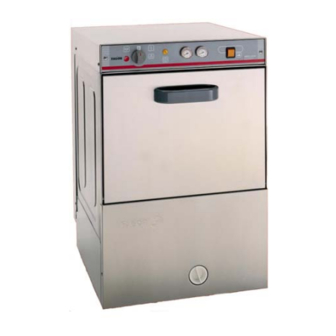
- Page 1 SERVICE MANUAL ********* OCTOBER 2007 GLASSWASHER Models: LVC – 21 W...
-
Page 2: Table Of Contents
0 TABLE OF CONTENTS TABLE OF CONTENTS ______________________________________________________ I QUICK START GUIDES______________________________________________________ 1 QUICK INSTALLATION _____________________________________________________ 2 SPECIFICATIONS ___________________________________________________________ 3 INSTALLATION ____________________________________________________________ 4 VISUAL INSPECTION _____________________________________________________ 4 INSTALLATION DIAGRAM ________________________________________________ 4 DATA PLATE ____________________________________________________________ 5 POSITIONING ____________________________________________________________ 5 WATER INSTALLATION___________________________________________________ 5 WATER DRAINAGE_______________________________________________________ 6 ELECTRICAL CONNECTION _______________________________________________ 7 INSTALLATION CHECKLIST_________________________________________________ 8... -
Page 5: Specifications
3 SPECIFICATIONS Model: LVC-21W PERFORMANCE/CAPACITIES Capacities Heating Elements Racks per hr.: 22 Electric wash tank heater: 2 Kw Wash Tank: 4gal. / 15.4 liters Electric booster heater: 2.8 Kw Water Consumption / Requirements Operating Cycles Gallons per hr. (Max. use): 20gal. / 75 liters Wash time (Seconds): 100 Gallons per cycles: .64gal. -
Page 6: Installation
4 INSTALLATION 4.1 VISUAL INSPECTION Upon receiving your new Fagor dishwasher, check the package and the machine for any damages that may have occurred during transportation. Visually inspect the exterior of the package. If damaged, open and inspect the contents with the carrier. Any damage should be noted and reported on the delivering carrier’s receipt. -
Page 7: Data Plate
4.3 DATA PLATE The data plate in located on one side of the machine. Under no circumstances should the data plate be removed from the unit. The data plate is essential to identify the particular features of your machine and is of great benefit to installers, operators and maintenance personnel. It is recommended that, in the event the data plate is removed, you copy down the essential information in this manual for reference before installation. -
Page 8: Water Drainage
THE DISPLAY OF THE PRESSURE GAUGE SHALL BE CLEARLY VISIBLE OF THE OPERATOR OF THE MACHINE. THE GAUGE SHALL HAVE INCREMENTS OF 1 psi (7 kpa) OR SMALLER AND SHALL BE ACCURATE TO ±2 psi (±14 kpa) IN THE 15-25 psi (103-172 kpa) RANGE. -
Page 9: Electrical Connection
4.7 ELECTRICAL CONNECTION − To access to the electrical connection block (R) (Fig. 1), remove the top cover (T) (Fig. 1) and the rear panel (P) (Fig. 1). Connect the wires as shown in figure 6. Insert the power cord through the cord holder (E) (Fig. -
Page 10: Installation Checklist
5 INSTALLATION CHECKLIST CHECK OFF THE FOLLOWING ITEMS AS THEY ARE COMPLETED BEFORE PROCEEDING TO OPERATE OR SERVICE THE GLASSWASHER. Has the dishwasher been checked for concealed/hidden damage? Has the dishwasher been properly leveled? Has the service voltage been checked to ensure that it meets the requirements listed on the dishwasher data plate? Has the dishwasher circuit breaker/service breaker been sized correctly, given the dishwasher’s amperage requirements? -
Page 11: Operations
6 OPERATIONS 6.1 WASHING Fig.8 Control Panel • Set selector switch (1) to . This will turn your machine ON. Indicator light (2) will illuminate. Machine will automatically begin to fill and heat the water in the boiler and tank to the proper temperatures. -
Page 12: Draining And Cleaning
6.3 DRAINING AND CLEANING Draining must occur EVERY DAY and if in a high application; It should be drained after each meal rush! Fig.8 Control Panel • Switch selector switch (1) to the 0 setting. (OFF) (Fig. 8) • Remove the overflow tube by inserting a finger into the top of the tube. (Fig.10) DO NOT REMOVE SCRAP BASKET! DO NOT LOOSE O’RING! •... -
Page 13: Detergent Control
Detergent Controller Rinse Controller and Priming Button Warning! If you require the installation of an NON FAGOR Detergent and Rinse pump, a form MUST be fill out prior to installation by your installer. Failure to do so, will void your Warranty. -
Page 14: Troubleshooting
First be sure that the “INSTALLATION CHECKLIST” in this manual was completed and check out that all the conditions still remains in effect. For support or further service information contact Fagor Service Department toll free at 1-866-GO-FAGOR (46-32467). The diagnosing, testing and repair of any electrical, mechanical device is to be performed solely by trained service technicians. - Page 15 SYMPTOM POSSIBLE CAUSE ACTION Timer faulty (M) Verify the programmer is rotating (M1, M2, M3). If not, check to see that the motor is receiving power. If so, replace the programmer assembly. Ohm out timer Glasswasher RUNS motor leads. continuously in the wash Faulty rinse valve (V1) Verify the wiring and voltage received;...
- Page 16 SYMPTOM POSSIBLE CAUSE ACTION Overflow tube not Check and remove. removed. Drain pump (BD) Open drain pump cover and remove debris. clogged. (Lower front panel; unscrew white removable cover, rotate c/cw) Glasswasher RUNS Drain hose kinked Make sure the drain hose is not kinked perfectly but NOT DRAINING.
-
Page 17: Electrical Diagram
8 ELECTRICAL DIAGRAM... -
Page 18: Wiring Schematic
9 WIRING SCHEMATIC... - Page 19 Maillo 14-1-98 Firma Fecha Mecanizado superficial Dibujado S. N. 19-10-94 Proyectado am/ve Comprobado Fagor Industrial,Koop.Elk, Mugatua B.D. Escala Plano numero HC-16383- LAVAVASOS Det. Sustituye al N° Plano hau ez daiteke erabil ez berrizta gure baimeni t z gabe Sustituido por...
-
Page 20: Timer (M)
10 TIMER (M) The cycle timer is comprised of 3 sections (M1 to M3). Each one has a 3 position micro switch (line /normally closed /normally open) and 1 drive motor. M1: This is the (ON) cycle micro, and stays activated throughout the completion of the cycle. The M1 line in (violet) wire comes from the press valve (P1) and feeds the (red ) normally closed position to... -
Page 21: Detergent Pump New Location Lvc-21W
12 DETERGENT PUMP NEW LOCATION LVC-21W Detergent Injector Hole to fix bracket Fig.1 New Bracket. Part #: Z208909 Button (screw) to adjust detergent amount Pipe going to the tank Second hole; use (1) Screw #Q152004 & (1)Nut #Q162030 to fix the bracket Procedure: 1- Open Front Bottom Panel 2- Be sure that the bracket on the pump is the one shown above (part #: Z208909) -
Page 22: Deliming
13 DELIMING In order to maintain dishwasher at optimum conditions, it is requested to remove lime and corrosion deposits on a frequent basis. A deliming solution should be available from your chemical supplier. Read and follow all instructions on the label of the deliming solution. Operations: •... -
Page 23: Warranty Guidelines
Fagor, when placing order. Part will be shipped free of charge. Using that number Distributor will fill out the Warranty Parts Form and fax/e-mail it to Fagor at the end of the month If service agency owns a package of spare parts, it is his responsibility to maintain original quantity of parts in stock. - Page 24 Fagor Commercial, Inc. 12800 NW 38 Ave. Miami, Fl. 33054 Tel: (305) 779 0170 Fax: (305) 779 0173 1-866-GO-FAGOR www.fagorcommercial.com...
Need help?
Do you have a question about the LVC–21W and is the answer not in the manual?
Questions and answers