Table of Contents
Advertisement
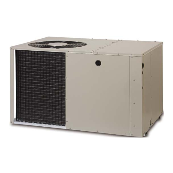
Q5RD SERIES
USER's MANUAL & INSTALLATION INSTRUCTIONS
Single Package Heat Pump - Single Stage, R-410A
Please read this information thoroughly and become familiar with the capabilities
and use of your appliance before attempting to operate or maintain this unit.
Keep this literature where you have easy access to it in the future. If a problem
occurs, check the instructions and follow recommendations given. If these
suggestions don't eliminate your problem, call your servicing contractor.
These instructions are primarily intended to assist qualifi ed individuals
experienced in the proper installation of this appliance. Some local codes
require licensed installation/service personnel for this type of equipment.
Read all instructions carefully before starting the installation.
DO NOT DESTROY. PLEASE READ CAREFULLY AND
KEEP IN A SAFE PLACE FOR FUTURE REFERENCE.
IMPORTANT
13 SEER
Advertisement
Table of Contents

Related Manuals for Nordyne Q5RD SERIES


Summary of Contents for Nordyne Q5RD SERIES
- Page 1 Q5RD SERIES 13 SEER USER’s MANUAL & INSTALLATION INSTRUCTIONS Single Package Heat Pump - Single Stage, R-410A IMPORTANT Please read this information thoroughly and become familiar with the capabilities and use of your appliance before attempting to operate or maintain this unit.
-
Page 2: Table Of Contents
USER INFORMATION IMPORTANT SAFETY INFORMATION About the Heat Pump ........3 Safety markings are used frequently throughout Operating Instructions ........ 3 this manual to designate a degree or level Cooling Operation ........3 of seriousness and should not be ignored. Heating Operation ........ -
Page 3: About The Heat Pump
USER INFORMATION ABOUT THE HEAT PUMP minutes following a previous operation or the interruption of the main electrical power. Your heat pump is a unique, all weather comfort- control appliance that will heat and cool your Emergency Heat home year round and provide energy saving Some thermostats may include a system mode comfort. -
Page 4: Important Safety Information
INSTALLER INFORMATION Before You Install this Unit IMPORTANT SAFETY INFORMATION The cooling load of the area to be conditioned must be calculated and a system of the proper WARNING: capacity selected. It is recommended that the area to be conditioned be completely insulated The information listed below and vapor sealed. -
Page 5: Minimum Clearances
Minimum Clearances • For highly resistive duct systems it may be Minimum clearances MUST be maintained from necessary to add an additional return air adjacent structures to provide room for proper duct and or supply to achieve maximum servicing and air circulation. DO NOT install unit performance and prevent coil icing and in a confi... -
Page 6: Return Duct
2. Fasten the collar ends with two self drilling Locating & Installing the Return Air Assembly sheet metal screws. To simplify installation, locate and install the 3. Position the collar over the opening and align return air assembly fi rst. If desired, the return the 4 holes in the collar with the 4 holes (or opening can be located inside a closet with dimples depending on model) in the rear panel. -
Page 7: Locating & Installing The Supply Dampers
SINGLE DUCT APPLICATION MULTIPLE DUCT APPLICATION Figure 5. Typical Duct Applications Locating & Installing the Supply Damper(s) Condensate Drainage When locating the supply damper(s), carefully A 3/4” condensate fi tting extends out of the side check fl oor joists and frame members that could of the unit as shown in Figure 7. -
Page 8: Electrical Connections
ELECTRICAL CONNECTIONS • See the unit wiring label for proper high and low voltage wiring. Make all electrical connections in accordance with all applicable codes and WARNING: ordinances. See Figures 10 & 11 (pages 20 & 21) To avoid electric shock, personal injury, or death, turn off the electric CAUTION: power at the disconnect or the main... -
Page 9: Overcurrent Protection
Overcurrent Protection Model Wire Color / Motor Air Flow Overcurrent protection must be provided at the Q5RD Speed Tap Speed (0.3 In. WC) branch circuit distribution panel and sized as shown on the unit rating label and according to applicable local codes. Generally, the best fuse 024K Black/T5 Med †... -
Page 10: Defrost Cycle Control
Defrost Cycle Control STARTUP & ADJUSTMENTS The Demand Defrost controls the defrost cycle in Pre-Start Checklist response to an adaptive demand algorithm that The following check list should be observed prior uses coil temperature and ambient temperature. to starting the unit. It provides user selectable defrost termination ... -
Page 11: Short Cycle Protection
temperature selector below the existing room Anti Short Cycle Timer Test temperature. Allow the cooling system to operate The 5 minute time delay feature can be bypassed for several minutes and check for the discharge by shorting the TEST pins together. of cool air at the supply registers. -
Page 12: Component Functions
correctly charged. UNIT MAINTENANCE • If the pressure measured in step 1 is less than the required liquid refrigerant pressure WARNING: determined in step 4, then there is too little charge in the system. Add refrigerant and To prevent electrical shock, repeat steps 1 through 3 until the system is p e rs o n a l i n j u r y, o r d e a t h , correctly charged. -
Page 13: Figures & Tables
FIGURES & TABLES Top View Electric Heater Power Supply Power Supply Low Voltage Supply Control Blower Access Panel Side View Access 17.86 Panel 15.36 10.10 1" 3/4" NPT Drain Connection 1.38 18.01 3.2 5.29 12.13 Back (Duct) View 9.15 1" 3.15 9.04 17.50... -
Page 14: Charging Tables - Cooling Mode
REFRIGERANT CHARGING TABLES - COOLING MODE Shaded boxes indicate fl ooded conditions. Rated design values. The suction pressure will be lower than design value if indoor air fl ow, entering dry bulb, or entering wet bulb temperature are lower than design. 1. -
Page 15: Charging Tables - Cooling Mode
REFRIGERANT CHARGING TABLES - COOLING MODE Shaded boxes indicate fl ooded conditions. Rated design values. The suction pressure will be lower than design value if indoor air fl ow, entering dry bulb, or entering wet bulb temperature are lower than design. 1. - Page 16 REFRIGERANT CHARGING TABLES - COOLING MODE Shaded boxes indicate fl ooded conditions. Rated design values. The suction pressure will be lower than design value if indoor air fl ow, entering dry bulb, or entering wet bulb temperature are lower than design. 1.
-
Page 20: Wiring Diagrams
WIRING DIAGRAMS Figure 10. Q5RD / PPH2RD Series Wiring Diagram - 2 & 2.5 Ton Units... - Page 21 Figure 11. Q5RD / PPH2RD Series Wiring Diagram - 3, 4 & 5 Ton Units...
- Page 22 Outdoor Thermostat Green (Factory Option) Brown Orange INDOOR T-STAT SUB-BASE DEFROST Accessory Heat Plug BOARD Typical Wiring (Field Supplied) for 1-Stage Cool, 1 Stage Electric Heat Optional 2nd Stage Outdoor Thermostat Green (Field Supplied) Outdoor Thermostat (Factory Option) Brown Orange INDOOR T-STAT SUB-BASE...
-
Page 24: Installation / Performance Checklist
INSTALLATION / PERFORMANCE CHECK LIST REFRIGERATION SYSTEM: INSTALLATION ADDRESS: Was unit given 24 hr warm up CITY _______________ STATE ____________ period for crankcase heaters (if applicable)? UNIT MODEL # ___________________________ Stage-1 Liquid Pressure (high side) ___________ UNIT SERIAL # ___________________________ Unit Installed Minimum Stage-1 Suction Pressure (low side) ___________ clearances per Figure 2...
Need help?
Do you have a question about the Q5RD SERIES and is the answer not in the manual?
Questions and answers