Table of Contents
Advertisement
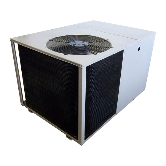
Q5RF SERIES
15 SEER
Single Package
Heat Pump - 2 Stage, R-410A
Please read this information thoroughly and become familiar with the capabilities
and use of your appliance
before attempting
to operate or maintain this unit.
Keep this literature where you have easy access to it in the future. If a problem
occurs, check the instructions and follow recommendations
given. If these
suggestions
don't eliminate your problem, call your Servicing
Contractor.
These
instructions
are primarily
intended
to assist
qualified
individuals
experienced
in the proper installation
of this appliance.
Some local codes
require
licensed
installation/service
personnel
for this type of equipment.
Please read all instructions
carefully before starting the installation.
Advertisement
Table of Contents

Related Manuals for Nordyne Q5RF Series


Summary of Contents for Nordyne Q5RF Series
- Page 1 Q5RF SERIES 15 SEER Single Package Heat Pump - 2 Stage, R-410A Please read this information thoroughly and become familiar with the capabilities and use of your appliance before attempting to operate or maintain this unit. Keep this literature where you have easy access to it in the future. If a problem occurs, check the instructions and follow recommendations given.
- Page 2 Forced Defrost Mode (Field Test) ..... 12 Anti Short Cycle Timer Test ...... 12 About the Heat Pump ........Heating Mode ........Cooling Mode ......... Operating Instructions ........ Cooling Operation ........Adjustment of Refrigerant Charge .... 13 Heating Operation ........Charging R410A Unit...
-
Page 3: Aboutthe Heat Pump
ABOUTTHE HEAT PUMP minutes following a previous operation or the interruption of the main electrical power. Your heat pump is a unique, all weather comfort- control appliance that will heat and cool your Emergency Heat home year round and provide energy saving Some thermostats may include a system mode... -
Page 4: Safety Information
GENERAL INFORMATION SAFETY iN FORMATION Single packaged heat pumps are ready for easy and immediate installation and can be readily WARNING: connected into the high static duct system of a home.This unit is completely assembled, wired, information listed below and run tested at the factory. This heat pump must followed during... -
Page 5: Air Duct System
Air Duct System Air ductsmustbe installedin accordance with the standardsof the NationalFire Protection Association"Standardfor Installationof Air Conditioning andVentilation Systems"(NFPA 90A), " Standard f orInstallation ofResidenceType Warm AirHeating andAirConditioning S ystems" (NFPA 90B), t heseinstructions, andallapplicable codes. NFPApublicationsare avaialableby writingto: National F ireProtection Association, P-Trap Batterymarch Park,Quincy, M E02269or visit www.NFPA.org onthe web. -
Page 6: Return Duct
1 2" 24" Supply Air Return Air Figure 3. Minimum Unit Clearances Figure 4. Return and Supply Air Fittings Installing Return & Supply Air Fittings The supply and return fittings are included with 2. Overlap the collar ends keeping the small the unit and located in the supply duct. - Page 7 NOTE: The return air box with grille and filter Locating & Installing the Supply Damper(s) (Figure 6) should not be located in heavy traffic When locating the supply damper(s), carefully areas like hallways or center of rooms. A good check floor joists and frame members that could spot is in a corner or under a table, if a minimum interfere with the installation of the damper or...
-
Page 8: Electrical Connections
ELECTRICAL CONNECTIONS See the unit wiring label for proper high and low voltage wiring. Make all electrical connections in accordance with all applicable codes and WARNING: ordinances. To avoid electric shock, personal CAUTION: injury, or death, turn off the electric power at the disconnect or the main Label... -
Page 9: Overcurrent Protection
Overcurrent Protection CAUTION: Overcurrent protection must be provided at the branch circuit distribution pane! and sized as shown on the unit rating !abe! and according to avoid personal injury app!icab!e !oca! codes. Generally, the best fuse property damage, make certain or breaker for any heat pump is the sma!!est that... -
Page 10: Demand Defrost Control
DemandDefrostControl Electric Heat Package (optional) Thedemand defrostboardcontrols the defrost This heat pump is shipped without an auxiliary cycle in responseto ambient temperature, electric heat kit installed. If electric heat is desired, outdoor coil temperatureand accumulated an accessory Heater Kit must be field installed. compressor runtime.The heat p ump isallowed to See Specifications Sheet for available kits and... - Page 11 Outdoor Thermostat (optional) Y1 = 1st Stage Heat Pump Y2 = 2rid Stage Heat Pump /_-- Green W1 = 1 st Stage Au× ary Heat I (from blower relay) Accessory Heat Plug Brown Orange ®1 Demand Defrost Board Typical Wiring (Field Supplied) for 2=Stage Cool, 1 Stage Electric Heat Y1 = 1st Stage Heat Pump Y2 = 2nd Stage Heat Pump W1 = 1st Stage Auxiliary Heat...
-
Page 12: Startup & Adjustments
STARTUP & ADJUSTMENTS temperature selector below the existing room temperature. Allow the cooling system to operate Pre-Start Checklist for several minutes and check for the discharge The following check list should be observed prior of cool air at the supply registers. to starting the unit. -
Page 13: Unit Maintenance
Cooling_ Mode Charging an R-410A Unit in Heating Mode When the TEST pins are shorted together for 1. Evacuate refrigerant system. more than 1 second, the Anti Short Cycle Timer 2. Weigh in the proper charge as shown on the will be bypassed. -
Page 14: Refrigerant Charging Charts For Cooling Mode Of Operation
Refrigerant Charging Charts for Cooling Mode of Operation Q5RF-X24K CHARGING CHART Remove refrigerant when above curw /_,_ _ 450 _c_ 425 o_ 400 Q_ 375 IAddrefrigerant when below curve LIQUID TEMPERATURE Figure 11. Charging Chart for 2 ton Units Q5RF-X36K CHARGING CHART Remove refrigerant when... - Page 15 Refrigerant Charging Charts for Cooling Mode of Operation =Continued Q5RF-X48K CHARGING CHART Remove refrigerant when above curve _" _'_ 425 IAddrefrigerant when below curve LIQUID TEMPERATURE Figure 13. Charging Chart for 4 ton Units Q5RF-X60K COOLING CHARGING CHART Remove refrigerant when above curw...
- Page 16 Refrigerant Charging Chart Legend for Heating Mode of Operation: Shaded boxes indicate flooded conditions. Rated design values. The suction pressure will vary from design value if outdoor air flow, entering dry bulb, or entering wet bulb temperatures vary. 1. All pressures are listed psig and all temperatures in °F 2.
- Page 17 Refrigerant Charging Chart Legend for Heating Mode of Operation: Shaded boxes indicate flooded conditions. Rated design values. The suction pressure will vary from design value if outdoor air flow, entering dry bulb, or entering wet bulb temperatures vary. 1. All pressures are listed psig and all temperatures in °F 2.
- Page 18 208/230V 60HZ/SINGLE PHASE Q5RF/PPH2RF SERIES SMALL PACKAGE H/P W/DEMAND DEFROST 2TON AND 3TON 1. Couper le courant avant de faire letretine. NOTES: 2. Employez uniquement des conducteurs en cuiver. 1. Disconnect all power before servicing. SEETABLEFOR 3. Ne convient pas aux installations de plus de 150V a la terre.
- Page 19 Q5RF/PPH2RF SERIES SMALL PACKAGE HIP W/DEMAND DEFROST 208/230V 60HZ/SINGLE PHASE 4 TON AND 5 TON t. Couper le courant avant de faire letretine. NOTES: 2. Employez uniquement des conducteurs en cuiver. 1. Disconnect all power before servicing• 3. Ne convient pas aux installations de plus de 150V a la terre.
-
Page 20: Component Functions
COMPONENT FUNCTIONS High Pressure Switch The high pressure switch is factory installed Low Pressure Switch and located in the compressor discharge line The low pressure switch is factory installed and internal to the unit. The switch is designed to de- located in the suction line internal to the unit.
Need help?
Do you have a question about the Q5RF Series and is the answer not in the manual?
Questions and answers