Table of Contents
Advertisement
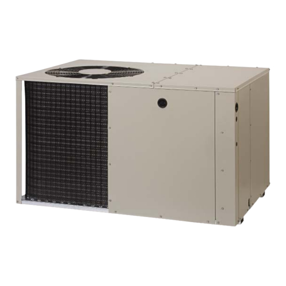
13 SEER
Single Package Heat Pump
Single Package Heat Pump
iMPORTANT:
Read this
owner information
to become
familiar
with
the capabilities
and use of your
appliance.
Keep this with literature
on other appliances
where
you have easy access
to
it in the future,
if a problem occurs, check
the instructions
and follow
recommendations
given,
if these suggestions
don't
eliminate
your
problem, call your installing
contractor
or distributor
in your area.
iNTRODUCTiON
Your heat pump isa unique, all weather comfort-
control system appliance. The basic operation
of the heating/cooling
system is described and
illustrated on page 1 of this man ual. The su rprising
fact that heat exists in air even at below-freezing
temperatures
is actually the basic law of physics
which the heat pump uses to provide energy
saving heating comfort. At outdoor temperatures
of 47 ° Fahrenheit
(or 8° Celsius), your heat
pump can deliver approximately
2 to 3 units of
heat energy per each unit of electrical energy
used, as compared to a maximum of only 1 unit
of heat
energy
produced
with conventional
heating systems.
During the cooling season,
the heat pump reverses the flow of the heat-
absorbing
refrigerant
to become
an energy-
efficient, central air conditioner.
Advertisement
Table of Contents

Subscribe to Our Youtube Channel
Related Manuals for Nordyne Q3RD


Summary of Contents for Nordyne Q3RD
- Page 1 13 SEER Single Package Heat Pump Single Package Heat Pump iMPORTANT: Read this owner information to become familiar with the capabilities and use of your appliance. Keep this with literature on other appliances where you have easy access it in the future, if a problem occurs, check the instructions and follow...
-
Page 2: Section 1. Owner Information
SECTION 1. OWNER INFORMATION SYSTEM SWITCH Your heat pump will heat and cool your home FAN SWITCH year round, saving your energy dollars. During the summer, a heat pump performs like any normal air conditioner. That is, the excess heat energy inside the home is absorbed... -
Page 3: Section 2. Installer Information
heating)will be used as a sourceof heat. Sustaineduse of electricresistance heat in 6ft. placeoftheheatpump will result i nanincrease in electricutilitycosts. Defrost -- During cold weather heating operation, theoutdoor u nit w illdevelop a coating ofsnowandiceontheheattransfer c oil. Thisis normal a ndtheunit w illperiodically d efrost i tself. Duringthe defrostcycle,the outdoorfan will stop,whilethecompressor continues t orunand heattheoutdoor c oil,causingthesnowandice... -
Page 4: Unpack The Unit
, Donot placethe unitin a confined space. shipped in the supply duct. They attach to the unit openings with a flange bead , If practical, place theheatpumpwhere itand arrangement, secured with two sheet metal theductswill beshadedfromtheafternoon screws. Note: For ease of access, install fitting sunwhenthe heatloadis greatest. -
Page 5: Ducting System
When locating the supply damper(s), carefully check floor joists and frame members that could interfere with the installation of the damper :ILTER or flexible duct. Ideally, the damper should be RETURN AIR located in the bottom of the main duct, forward of center of the home, at least three feet from the nearest register. - Page 6 c. Theflexible ductsmaybecuttotherequired length,see instructions packedwith duct. Keep all ducts as short and straightas possible.Avoidsharpbends. d. Ducts may be spliced with sheet metal sleeves andclamps. ( SeeDucting Installation Accessories b elow.) e. Once the inner duct is connectedto the proper f itting, t heinsulation a ndplastic sleeve shouldbe pulledoverthe connection and clamped.
-
Page 7: Condensate Drain
Place the desired blower speed lead CONDENSATE DRAIN on the "NO" terminal of the blower relay. another wire (field A 3/4" condensate fitting extends out of the side supplied) to bundle the remaining motor of the unit. The drain trap, shipped in the lead up and out of the way. - Page 8 FROM SLOWER RELAY __/_ Green ©- o ?_-.) --I------7 3- Orange __. Srown iNDOOR THERMOSTAT SUB-BASE DEFROST Accessory Heat Plug BOARD Typical Wiring (Field Supplied) for 1=Stage Cool, 1 Stage Electric Heat FROM SLOWER RELAY Optional Outdoor Thermostat (Field Supplied) _(_.) I-±...
- Page 9 with an ON-AUTO fan switch which allows the home owner to operate the indoor blower when air circulation is desired. Connect the low voltage wires to the respective terminals on the thermostat base. See thermo- stat instruction sheet for more detailed informa- tion.
-
Page 10: System Operation
Select t hecorrectsizeheatpackage forthe balanced air distribution. Examine installation. ductwork for leaks or obstruction ifinsufficient air is detected. Follow installation i nstructions p rovided with eachheaterkit. Set the thermostat fan switch to AUTO; • Installationis most easily accomplished blower should stop running. before making ductorelectrical connections. -
Page 11: Outdoor Temperature
13 SEER - Refrigerant Charging Tables for Cooling Mode of Operation OUTDOOR TEMPERATURE (°F) Suct. Dis. Dis. Dis. Dis. Dis. Dis. Dis. Dis. Dis. Dis. Dis. Dis. Dis. Dis. Dis. Dis. Press. Press. Temp. Press. Temp. Press. Temp. Press. Temp. Press. Temp. Press. Temp. Press. Temp. Press. Temp. _22_ 1_5! _ , _:57... - Page 12 13 SEER = Refrigerant Charging Tables for Cooling Mode of Operation Continued ]'ON Suct. Dis. Dis. Dis. Dis. Dis. Dis. Dis. Dis. Dis. Dis. Dis. Dis. Dis. Dis. Dis. Dis. Press. Press. Temp. Press. Temp. Press. Temp. Press. Temp. Press. Temp. Press. Temp. Press. Temp. Press. Temp. t83 14s tgs 148 208 is0 222 t52 252:: , _70.
- Page 13 13 SEER = Refrigerant Charging Tables for Cooling Mode of Operation Continued Suct. Dis. Dis. Dis. Dis. Dis. Dis, Dis. Dis. Dis. Dis. Dis. Dis. Dis. Dis. Dis. Dis. Press. Press. Temp. Press. Temp. Press. Temp. Press. Temp. Press. Temp. Press. Temp. Press. Temp. Press. Temp. 166 iiiiiiiiii_i!iiii,iiiiiil_69iiii_ii iiiili_oiXiXii.iiiilii_ii:751iiiii iHiiii262;:iii_!i.iHiiiii_iX791ili!ii!i...
- Page 15 Small Packaged Heat Pump - Single Phase NOTES: Disconnect all power before servicing, Couper le courant avant de faire letretien. For supply connections use copper conductors only. Employez uniquement des conducteurs en cuivre Not suitable on systems that exceed 150V to ground, Ne convient pas aux installations de plus de 150V a la terre.
- Page 16 Small Packaged Heat Pump - Single Phase NOTES: Disconnect all power before servicing. Couper le courant avant de faire letretien. For supply connections use copper conductors only. Employez uniquement des conducteurs en cuivre Not suitable on systems that exceed150 V to ground. Ne convient pas aux installations...
Need help?
Do you have a question about the Q3RD and is the answer not in the manual?
Questions and answers