Nordyne R-410A User's Manual & Installation Instructions
2 stage r-410a single package heat pump 15 seer
Hide thumbs
Also See for R-410A:
- Installation instructions manual (25 pages) ,
- User's manual & installation instructions (20 pages) ,
- User manual and installation instructions (20 pages)
Table of Contents
Advertisement
USER's MANUAL & INSTALLATION INSTRUCTIONS
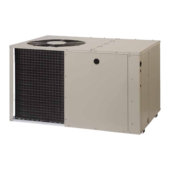
2 Stage R-410A Single Package Heat Pump
15 SEER
IMPORTANT
Please read this information thoroughly and become familiar with the capabilities
and use of your appliance before attempting to operate or maintain this unit.
Keep this literature where you have easy access to it in the future. If a problem
occurs, check the instructions and follow recommendations given. If these
suggestions don't eliminate your problem, call your NORDYNE Servicing
Contractor (Service PRO).
These instructions are primarily intended to assist qualifi ed individuals
experienced in the proper installation of this appliance. Some local codes
require licensed installation/service personnel for this type of equipment.
Please read all instructions carefully before starting the installation.
DO NOT DESTROY. PLEASE READ CAREFULLY AND
KEEP IN A SAFE PLACE FOR FUTURE REFERENCE.
Advertisement
Table of Contents

Related Manuals for Nordyne R-410A


Summary of Contents for Nordyne R-410A
- Page 1 Keep this literature where you have easy access to it in the future. If a problem occurs, check the instructions and follow recommendations given. If these suggestions don’t eliminate your problem, call your NORDYNE Servicing Contractor (Service PRO). These instructions are primarily intended to assist qualifi ed individuals experienced in the proper installation of this appliance.
-
Page 2: Table Of Contents
SAFETY INFORMATION .......3 Defrost Cycle Control ........ 9 Ambient Sensor Mounting .......11 USER INFORMATION ........3 Electric Heat Package ......11 About the Heat pump ........ 3 Operating Instructions ....... 3 SYSTEM OPERATION .........12 Cooling Operation ........3 Pre - Start Checklist .........12 Heating Operation ........ -
Page 3: Safety Information
SAFETY INFORMATION Operating Instructions IMPORTANT: Please read all instructions before Cooling Operation servicing this equipment. Pay attention to all 1. Set the thermostat’s system mode to COOL safety warnings and any other special notes or AUTO and change the fan mode to AUTO. highlighted in the manual. -
Page 4: System Shutdown
At the beginning of the defrost cycle, both the outdoor condenser fan and compressor will CAUTION: turn off. After approximately 30 seconds, the compressor will turn on and begin to heat the This unit uses refrigerant R-410A. DO NOT outdoor coil causing the ice and snow to melt. under any circumstances use any other NOTE: While the ice and snow is melting, some refrigerant in this unit. -
Page 5: Heat Pump Installation
HEAT PUMP INSTALLATION 6 ft. Locating the Heat pump 24" • Select a solid, level position, preferably on a concrete slab, slightly above the grade level, and parallel to the home. DO NOT PLACE UNIT UNDER THE HOME. • The hot condenser air must be discharged up and away from the home, and if possible, in a direction with the prevailing wind. -
Page 6: I N S Ta L L I N G R E T U R N A N D S U P P Ly
INSTALLING RETURN AND LOCATING AND INSTALLING THE SUPPLY AIR FITTINGS RETURN AIR ASSEMBLY To simplify installation, locate and install the The supply and return fi ttings are included with return air assembly fi rst. If desired, the return the unit and located in the supply duct. They opening can be located inside a closet with attach to the unit openings (Figure 4) with a louvered doors that has an open area equal to... -
Page 7: Locating And Installing The
LOCATING AND INSTALLING THE DUCTING SYSTEM SUPPLY DAMPER(S) Air ducts should be installed in accordance with the standards of the National Fire Protection When locating the supply damper(s), carefully Association “Standard for Installation of Air check fl oor joists and frame members that could Conditioning and Ventilation Systems”... -
Page 8: Connecting The Return And Supply Air Flexible Ducts
Note: For highly resistive duct systems it may be 2. Locate the orange, black and red wires necessary to add an additional return air duct and terminated to the blower motor. The orange or supply to achieve maximum performance and wire controls the low speed cooling and heating prevent coil icing and refrigerant fl... -
Page 9: Overcurrent Protection
Low Pressure Switch The low pressure switch is factory installed and located in the suction line internal to the unit. The switch is designed to protect the compressor if a loss of charge occurs. Under normal conditions, the switch is closed. If the suction pressure falls below 5 psig, then the switch will open and de-energize the unit. - Page 10 Green (from Blower Relay) Brown Orange INDOOR DEFROST Accessory Heat Plug THERMOSTAT BOARD SUB-BASE Figure 9. Typical Wiring (Field Supplied) for 2-Stage Cool, 2 Stage Electric Heat Air Flow Model Q5RF Wire Color/Speed Tap Motor Speed (@ 0.3 in WC) Orange/T2 Medium/Low* Black/T3...
-
Page 11: Ambient Sensor Mounting
Control is uncalibrated when power is applied. 6. Install one spacer next between the Calibration occurs after a defrost cycle. The plastic clip and mounting bracket. control initiates defrost after 34 minutes of 7. Bend the mounting bracket into position. accumulated compressor run time in heating Install the mounting bracket to the unit with coil temperature below 35°... -
Page 12: System Operation
SYSTEM OPERATION setting until the whole system de-energizes. Immediately lower the thermostat temperature Pre-Start Checklist to the original setting and verify that the indoor The following check list should be observed prior blower is energized. After approximately 3 to starting the unit. ... -
Page 13: Anti Short Cycle Timer Test
Anti Short Cycle Timer Test determined in step 4, then there is too much charge in the system. Remove refrigerant and The 3 minute time delay feature can be bypassed repeat steps 1 through 3 until the system is by shorting the “TEST” pins together. correctly charged. -
Page 14: Refrigerant Charging Charts For Cooling Mode Of Operation
Refrigerant Charging Charts for Cooling Mode of Operation Q5RF-X24K CHARGING CHART R em ove refrigerant w hen above c urve Add refrigerant w hen below c urve LIQUID TEMPERATURE (F) Figure 11. Charging Chart for 2 ton Units Q5RF-X36K CHARGING CHART R em ove refrigerant w hen above c urve Add refrigerant w hen below c urve LIQUID TEMPERATURE (F) - Page 15 Refrigerant Charging Charts for Cooling Mode of Operation - Continued Q5RF-X48K CHARGING CHART R em ove refrigerant w hen above c urve Add refrigerant w hen below c urve LIQUID TEMPERATURE (F) Figure 13. Charging Chart for 4 ton Units Q5RF-X60K COOLING CHARGING CHART R em ove refrigerant w hen above c urve Add refrigerant w hen below c urve...
-
Page 18: Wiring Diagrams
YELLOW YELLOW BLACK BLUE YELLOW BLUE BLUE THERMISTOR THERMISTOR AMBIENT COIL FUSE Figure 15. Q5RF/PPH2RF Series Wiring Diagram - 2 & 3 Ton Units... - Page 19 YELLOW BLACK YELLOW BLUE BLUE BLUE BLUE WHITE BROWN THERMISTOR THERMISTOR AMBIENT COIL FUSE Figure 16. Q5RF/PPH2RF Series Wiring Diagram - 4 & 5 Ton Units...
- Page 20 INSTALLER PLEASE LEAVE THESE INSTALLATION INSTRUCTIONS WITH THE HOMEOWNER. 709064B (Replaces 709064A) ¢709064-¤ Specifi cations and illustrations subject to change without notice or incurring obligations. 709064B O’Fallon, MO Printed in U.S.A. (09/09)
Need help?
Do you have a question about the R-410A and is the answer not in the manual?
Questions and answers