Table of Contents
Advertisement
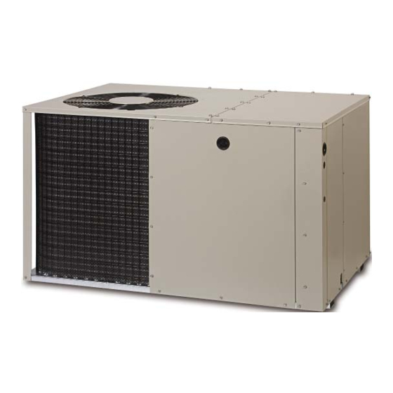
Q5RD SERIES
13 SEER
Single Package Heat Pump =Single Stage, R-410A
Please read this information thoroughly and become familiar with the capabilities
and use of your appliance
before attempting
to operate or maintain this unit.
Keep this literature where you have easy access to it in the future. If a problem
occurs, check the instructions and follow recommendations
given. If these
suggestions
don't eliminate your problem, call your servicing
contractor.
These
instructions are primarily
intended to assist
qualified
individuals
experienced
in the proper installation of this appliance.
Some local codes
require
licensed
installation/service
personnel
for this type of equipment.
Read all instructions carefully before starting the installation.
Advertisement
Table of Contents

Subscribe to Our Youtube Channel
Related Manuals for Nordyne Q5RD Series


Summary of Contents for Nordyne Q5RD Series
- Page 1 Q5RD SERIES 13 SEER Single Package Heat Pump =Single Stage, R-410A Please read this information thoroughly and become familiar with the capabilities and use of your appliance before attempting to operate or maintain this unit. Keep this literature where you have easy access to it in the future. If a problem occurs, check the instructions and follow recommendations given.
- Page 2 iMPORTANT SAFETY iNFORMATiON About the Heat Pump ........Safety markings are used frequently throughout Operating instructions ........ this manual to designate a degree or level Cooling Operation ........of seriousness and should not be ignored. Heating Operation ........WARNING indicates a potentially hazardous situation...
-
Page 3: Aboutthe Heat Pump
ABOUTTHE HEAT PUMP minutes following a previous operation or the interruption of the main electrical power. Your heat pump is a unique, all weather comfort- control appliance that will heat and cool your Emergency Heat home year round and provide energy saving Some thermostats may include a system mode... -
Page 4: Important Safety Information
Before You install this Unit iMPORTANT SAFETY iNFORMATiON _ The cooling load of the area to be conditioned must be calculated and a system of the proper WARNING: capacity selected. It is recommended that the area to be conditioned be completely insulated information listed below... -
Page 5: Heat Pump Installation
Minimum Clearances For highly resistive duct systems it may be Minimum clearances MUST be maintained from necessary to add an additional return adjacent structures to provide room for proper duct and or supply to achieve maximum servicing and air circulation. DO NOT install unit performance prevent coil... -
Page 6: Locating & Installing The Return Air Assembly
2. Fasten the collarendswith two self drilling Locating & Installing the Return Air Assembly sheetmetal s crews. To simplify installation, locate and install the 3. Position thecollarovertheopening andalign return air assembly first. If desired, the return the 4 holesin thecollarwiththe 4 holes(or opening can be located inside a closet... -
Page 7: Condensate Drainage
SINGLE DUCT APPLICATION MULTIPLE DUCT APPLICATION Figure 5. Typical Duct Applications Locating & Installing the Supply Damper(s) Condensate Drainage When locating the supply damper(s), carefully A 3/4" condensate fitting extends out of the side check floor joists and frame members that could of the unit as shown in Figure 7. -
Page 8: Electrical Connections
ELECTRICAL CONNECTIONS See the unit wiring label for proper high and low voltage wiring. Make all electrical connections in accordance with all applicable codes and /K WARNING: ordinances. See Figures 10 & 11 (pages 20 &21) To avoid electric shock, personal injury, or death, turn off the electric CAUTION'. -
Page 9: Overcurrent Protection
OvercurrentProtection Model Wire Color / Motor Air Flow Overcurrent protection mustbeprovided atthe Q5RD SpeedTap Speed (0.3 In.WC) branchcircuitdistribution paneland sizedas shownon theunitratinglabelandaccording to applicable localcodes. G enerally, the bestfuse 024K Black/T5 Med i- or breakerfor any heatpump is the smallest High 1133 size that will permit the equipment to run under... -
Page 10: Startup & Adjustments
DefrostCycleControl STARTUP & ADJUSTMENTS TheDemand Defrost controls t hedefrost c yclein Pre-Start Checklist response toanadaptive demand algorithm that The following check list should be observed prior usescoiltemperature a ndambient temperature. to starting the unit. It providesuserselectable defrosttermination -_ Is the unit level? Unit should be level or slightly temperatures ( 50 °... -
Page 11: Short Cycle Protection
temperature selectorbelowthe existingroom Anti Short Cycle Timer Test temperature. Allow thecooling system tooperate The 5 minute time delay feature can be bypassed forseveral m inutes andcheckforthedischarge by shorting the TEST pins together. of coolairat thesupplyregisters. Heating Mode Short Cycle Protection When the TEST pins are shorted together for The control circuit is equipped with a time-delay more than 1 second,... -
Page 12: Component Functions
correctly charged. UNiT MAINTENANCE If the pressuremeasured in step 1 is less thanthe requiredliquidrefrigerant pressure /K WARNING: determined in step4, thenthereis too little chargein the system.Add refrigerant a nd repeatsteps1 through3 untilthe systemis personal injury, death, correctly charged. disconnect all electrical power Chargingan R-410AUnit in Heating... -
Page 13: Figures & Tables
FIGURES & TABLES Top View Heater Power Supply ipply Low Voltage Supply Side View 17 36 1.38 Back (Duct) View 9,15 14" diameter 12" diameter (12" for 024k) Supply Duct Return Duct pening Opening Figure 9. Q5RD Unit Dimensions Q5RD- Length (L) Width (W) Height (H) -
Page 14: Outdoor Temperature
REFRIGERANT CHARGING TABLES - COOLING MODE Shaded boxes indicate flooded conditions. Rated design values. The suction pressure will be lower than design value if indoor air flow, entering dry bulb, or entering wet bulb temperature are lower than design. 1. All pressures are listed psig and all temperatures in °F 2. - Page 15 REFRIGERANT CHARGING TABLES - COOLING MODE Shaded boxes indicate flooded conditions. Rated design values. The suction pressure will be lower than design value if indoor air flow, entering dry bulb, or entering wet bulb temperature are lower than design. 1. All pressures are listed psig and all temperatures in °F 2.
- Page 16 REFRIGERANT CHARGING TABLES - COOLING MODE Shaded boxes indicate flooded conditions. Rated design values. The suction pressure will be lower than design value if indoor air flow, entering dry bulb, or entering wet bulb temperature are lower than design. 1. All pressures are listed psig and all temperatures in °F 2.
-
Page 17: Charging Tables - Heating Mode
REFRIGERANT CHARGING TABLES - HEATING MODE: Shaded boxes indicate flooded conditions. Rated design values. The suction pressure will vary from design value if outdoor air flow, entering dry bulb, or entering wet bulb temperatures vary. 1. All pressures are listed psig and all temperatures in °F 2. - Page 18 REFRIGERANT CHARGING TABLES - HEATING MODE: Shaded boxes indicate flooded conditions. Rated design values. The suction pressure will vary from design value if outdoor air flow, entering dry bulb, or entering wet bulb temperatures vary. 1. All pressures are listed psig and all temperatures in °F 2.
-
Page 19: Refrigerant Charging
REFRIGERANT CHARGING TABLES - HEATING MODE: Shaded boxes indicate flooded conditions. Rated design values. The suction pressure will vary from design value if outdoor air flow, entering dry bulb, or entering wet bulb temperatures vary. 1. All pressures are listed psig and all temperatures in °F 2. - Page 20 SMALL PACKAGE HEAT PUMP 208/230 VOLT 60HZ/SINGLE PHASE NOTES: 1. Disconnect all power before servicing. 4. For replacement wires use conductors suitable for 105°C. 1. Couper le courant avant de faire letretine. 2. For supply connections use copper conductors only. 2.
- Page 21 SMALL PACKAGED HEAT PUMP- SINGLE PHASE 208/230 VOLT 60HZ NOTES: "t3 1. Disconnect all power before servicing. 4. For replacement wires use conductors suitable for 105 ° C. 7. Couper le courant avant de faire letretien. 2. For supply connections use copper conductors only.
- Page 22 Outdoor Thermostat , _ _ _ Green (Factory Option) ©- ©- - _-_ ©- o (_ --_--Orange ©- _ _= Brown iNDOOR T=STAT SUB=BASE DEFROST Accessory Heat Plug BOARD Typical Wiring (Field Supplied) for 1-Stage Cool, 1 Stage Electric Heat Optional 2rid Stage Outdoor...
-
Page 24: Installation
California to cause cancer, birth defects or other reproductive harm. iNSTALLER: PLEASE LEAVE THESE iNSTALLATiON iNSTRUCTiONS WiTH THE HOMEOWNER. NORDYNE Ill IIIIIlllllllllllll COMPL_E COMFOR% GENUINEVALUE. Specifications & illustrations subject to change without notice or incurring obligations. O' Fallon, MO I Printed in U.S.A. (06/10)
Need help?
Do you have a question about the Q5RD Series and is the answer not in the manual?
Questions and answers