Table of Contents
Advertisement
Advertisement
Table of Contents
Troubleshooting

Related Manuals for BullFrog Spas


Summary of Contents for BullFrog Spas
- Page 1 Bullfrog Spas Owners Manual...
- Page 2 QUICK REFERENCE To assist you with the installation and maintenance service of your new spa, please fill out the following information and keep it on hand for future reference. Spa Information Spa Model: ____________________________________________________________________________________ Serial Number: ______________________________________________________________________________ Dealership: _____________________________________________________________________________________ Dealer’s Phone Number: _____________________________________________________________ Date Purchased: ___________________________________________________________________________...
-
Page 3: Table Of Contents
TABLE OF CONTENTS Spa Maintenance Important Overview ............................Draining & Changing Spa Water ................Filter Maintenance Important Safety Instructions ........................... Light Replacement Safety Instructions ..................................................Spa Shell Care Warning Signs ........................................................JetPak Plumbing Care ........................ Spa Cabinet Care Spa Start Up/ Controls .......................... -
Page 4: Important Overview
IMPORTANT OVERVIEW Congratulations on your purchase of a Bullfrog Spas A Series or R Series Hot Tub² . Bullfrog Spas are the world’s only spas equipped with the patented JetPak System™. JetPak® technology delivers incredible power, maximum versatility and allows you to upgrade your spa’s jetting with new JetPaks®, both now and in the future. -
Page 5: Important Safety Instructions
IMPORTANT SAFETY INSTRUCTIONS Save these instructions DANGER: Risk of Electric Shock. As per UL requirements (U.S.), install spa at least 5 feet (1.5m) from all metal surfaces. A spa may be Safety Instructions installed within 5 feet (1.5m) of metal surfaces if each metal surface is permanently connected by a minimum of No. - Page 6 Before entering the spa, measure the water temperature with an WARNING: Risk of Fatal Hyperthermia. Hyperthermia occurs accurate thermometer since tolerances of water temperature regulating when the internal temperature of the body reaches a level several degrees devices may vary. above the normal body temperature of 98.6˚...
- Page 7 WARNING: Risk of Injury or Accidental Drowning: Do not use spa CAUTION: Unauthorized Access. Secure the spa area against without filters, filter plate, and filter SnapCaps™ installed; these parts unauthorized access. Make sure all spa barriers (fences, enclosures, etc.) serve as a barrier against bodily entrapment against the filter suction meet all applicable national and local codes.
-
Page 8: Warning Signs
Warning Signs Included with the spa are three warning signs to inform users and guests of the risk involved with using a spa. All of these warning signs are suitable for indoor and outdoor use. Place these warning signs in a noticeable place adjacent to the spa. -
Page 9: Spa Start Up/ Controls
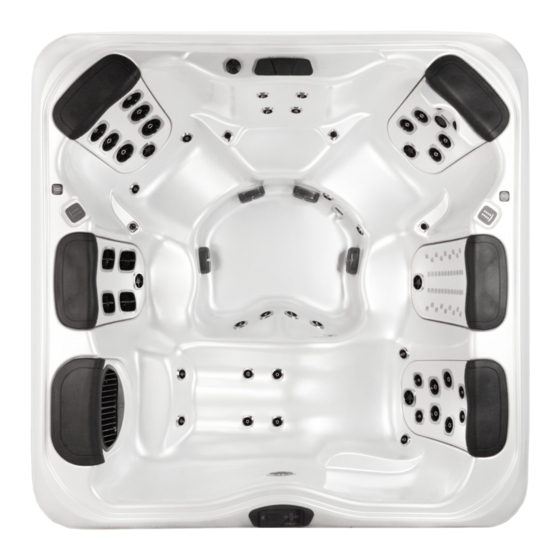
SPA START UP Spa Overview (A7L Pictured) -
Page 10: Equipment Compartment
Equipment Compartment Ozone* Control Center Light Drain Outlet *optional Safety Certificate Water Feature Filter Pump I Wifi Module* Product Information Water Heater Pump II Subwoofer*... -
Page 11: Filling Your Spa
IMPORTANT: Never fill the spa with soft water unless an appropriate mineral install the cover, refer to the Cover Installation Instructions included with the supplement is immediately added (see your authorized Bullfrog Spas Dealer). cover. If your water is extremely hard, it is preferable to either dilute the water’s... -
Page 12: Control System
Control System IMPORTANT : Your Bullfrog Spa is equipped with one of 3 types of control pads, A900 (5 Button), R600 (6 Button) and S600 (6 Button). Locate the control system on your spa by matching it with the photos provided and follow the specific instructions for operation of your specific control system. - Page 13 A Series Spas- A900 without the possibility of energizing the heater under low-flow or no-flow conditions. Nothing comes on automatically, but the pump(s) can be energized by selecting the “Jets” buttons. If the spa has a Circ. Pump, it can be turned on and off by pressing the “Circ Pump”...
-
Page 14: The Main Screen
Once the system has exited Priming Mode, the top-side panel will display The Main Screen the Main Screen, but the display will not show the temperature yet, as shown below. This is because the system requires approximately 1 minute of water Spa Status flowing through the heater to determine the water temperature and display it. - Page 15 The Spa Screen Navigation Navigating the entire menu structure is done with the 5 buttons on the control The Main Screen The Spa Screen panel. When a text item changes to white during navigation, that indicates the One Press Activation item is selected for action.
-
Page 16: The Settings Screen
The Setting Screen Dual Temperature Range (High vs. Low) This system incorporates two temperature range settings with independent set temperatures. The specific range can be selected on the Settings screen Programming, Etc. The Settings Screen is where all programming and other spa behaviors are and is visible on the Main Screen in the upper right corner of the display. - Page 17 Saving Settings The Time-of-Day screen is a simple, editable screen that illustrates a feature of Ready-in-Rest Mode READY/REST appears in the display if the spa is in Rest Mode and the Jets the control that applies to all other editable screens as well. 1 Button is pressed.
-
Page 18: Adjusting Filtration
Adjusting Filtration Purge Cycles NOTE: Your spa’s factory default filter cycle start times are 8:00am In order to maintain sanitary conditions, as well as protect against freezing, and 6:00pm daily. When using the most economical “rest” mode, it is secondary water devices will purge water from their respective plumbing by recommended that you adjust the filtration cycles to run just prior to the time running briefly at the beginning of each filter cycle. - Page 19 Panel Back Hold Mode Hold Mode is used to disable the pumps during service functions like cleaning or replacing the fi lter. Hold Mode will last for 1 hour unless the mode is exited manually. If spa service will require more than an hour, it may be best to simply shut Unlocking down power to the spa.
- Page 20 Information System Information System Model (preferences continued) System Information Displays the Model Number of the The System Information Menu displays various settings and Software ID (SSID) identifi cation of the particular system. As each item in the System. Time Display System Model Back menu is highlighted, the detail for that item is displayed at...
- Page 21 Utilities – GFCI Test Feature Utilities- GFCI Test Feature The Ground Fault Circuit Interrupter The Ground Fault Circuit Interrupter (GFCI) is an important GFCI Status - Passed safety device and is required equipment on a hot tub (GFCI) is an important safety device installation.
- Page 22 After turning the power on at the main power panel, the top-side panel display will go through specifi c sequences. These sequences are normal and display a variety of information regarding the confi guration of the hot tub control. R Series (R600) & Swim Spa (S600) Spas Priming Mode...
- Page 23 Priming the Pumps Temperature while the numbers are fl ashing in the LCD As soon as the above display appears on the panel, push the “Jet” button once to start Pump 1 in low-speed and then Pressing the MENU button while the numbers are fl ashing again to switch to high-speed.
-
Page 24: Show And Set Time Of Day
Hold Mode is used to disable the pumps during service functions like cleaning or replacing the fi lter. Hold Mode will last for Temperature while the numbers are fl ashing in the LCD. 1 hour unless the mode is exited manually. Pressing the MENU button while the numbers are fl... -
Page 25: Temperature And Temp Range
For example: High Range might be set between 80°F and 104°F. Low Range might be set between 50°F and 99°F. Indicates Flashing or Changing Se Indicates Alternating or Progressi Freeze Protection is active in either range. Temperature and Temp Range A temperature button, used for “A See Ready and Rest on Page 6 menu or dedicated “Choose”... - Page 26 may not show a current temperature until the heater pump has been running for a minute or two While Pump 1 High can be turned on and o , Pump 1 Low will run until set temperature is reache Flip (Invert) Display Mode-Ready and Rest Main Screen Indicates Flashing or Changin...
- Page 27 If the heater pump is a 2-Speed Pump 1, READY Mode will circulate water every 1/2 hour, using Pump 1 Low, in order to maintain a constant water temperature, heat as needed, and refresh the temperature display. This is known as “polling.” REST Mode will only allow heating during programmed fi...
- Page 28 cannot be adjusted. the MENU button from the main screen (normal operation) will The control can be restricted to prevent unwanted use or temperature adjustments. enter the menus. Temperature Lock allows access to a reduced selection of menu items. Typical use of the Temperature button(s) allows changing the Set Locking the panel prevents the controller from being used, but all automatic functions are still active.
- Page 29 Typical use of the Temperature button(s) allows changing the Set Temperature while the numbers are fl ashing in the LCD. Main Filtration Pressing the MENU button while the numbers are fl ashing will also enter the menus. Filter cycles are set using a start time and a duration. Start time is indicated by an “A” or “P” in the bottom right corner of The menus can be exited with certain button the display.
- Page 30 Typical use of the Temperature button(s) allows changing the Set Temperature while the numbers are fl ashing in the LCD. Pressing the MENU button while the numbers are fl ashing will also Preferences enter the menus. Preferences The menus can be exited with certain button presses.
- Page 31 Utilities and Information Additional Utilities INFO (System Information sub-menu) Utilities The System Information Menu displays various settings and identification of In addition to INFO, The Utilities Menu contains the following: the particular system. As each item in the menu is highlighted, the detail for that item is displayed at the bottom of the screen.
- Page 32 Indicates Flashing or Changing Segment Indicates Alternating or Progressive Message - every 1/2 second A temperature button, used for “Action” Utilities Main Screen menu or dedicated “Choose” button, depending on control panel ° ° Waiting time that keeps the last change to a menu item. While the Temperature is ***** Waiting time (depends on menu item) that reverts to original setting and...
- Page 33 Utilities-GFCI Test Feature Forcing the GFCI Trip Test The installer can cause the GFCI Trip Test to occur sooner by initiating it A GFCI is an important safety device and is required equipment on a hot tub using the above menu. The GFCI should trip within several seconds and the Utilities –...
- Page 34 Utilities-Fault Log A Little History can tell a lot The Fault Log stores up to 24 events in memory Utilities – Fault Log and they can be reviewed under the Fault Log Menu. Each event captures a Fault Message Code, how many days have passed since the fault, Time of the fault, Set Temperature during the fault, and Sensor A and B temperatures A Little History can tell a lot during the fault.
-
Page 35: Interchanging Jetpaks
Step 3: While applying pressure downward on the manifold push the manifold JETPAKS away from you toward the inside of the spa to release the manifold from the wall clip assembly, then lift the plate straight up to remove. Interchanging JetPaks- A & R Series Step 1: Put the spa in “Hold”, this will prevent the pump(s) from activating (see Control Systems). - Page 36 Interchanging JetPaks- Swim Spas Step 4: Loosen the two PVC unions, pull the manifold out from in between the two water unions. Step 1: Put the spa in “Hold”, this will prevent the pump(s) from activating (see Control System). Step 2: Carefully, remove the head rest and SnapCap™ by lifting upwards .
- Page 37 The in-line filter should be cleaned anytime the water feature seems to have reduced flow and/ or the water feature seems disrupted. A & R Series Spas NOTE: Always makes sure the water feature is in the OFF position when the spa cover is in place! The water feature is turned on or off by adjusting the Water Feature Control Valve located next to the water feature.
- Page 38 • To increase jet water pressure, turn the valve handle counter clockwise • To decrease jet water pressure, turn the valve handle clockwise Adjustable Jets Swim Spas To adjust the water flow on adjustable jets, simply turn the outer ring.
-
Page 40: Water Care & Chemistry
WATER CARE & CHEMISTRY Overview of Water Chemistry Maintaining Your Spa Water Water Quality Maintenance Tap water that is safe to drink is not always safe for a spa. Normal tap water Maintaining the quality of the spa water within specified limits will enhance is usually filled with minerals and microcontaminants that are not visible to your enjoyment of the spa and prolong the life of its equipment. - Page 41 NOTE: Ozone purification is recommended only as a supplement to the above interfere with sanitiser effectiveness. Super Sanitation is achieved by adding sanitisers. Ozone Purifiers greatly enhance the quality of the spa water when high levels of Spa Fresh Shock or equivalent which is a non-Chlorine shock used in conjunction with an industry standard spa chemical maintenance (Potassium Peroxymonosulfate or equivalent).
- Page 42 Proper total alkalinity levels are important to ensure substances, Super Sanitise the water. Or, non-filterable micro-particulate waste optimal chemical balance in spas. Low TA can cause the pH to be unstable (e.g. dust) has contaminated the water. To remove these substances use causing the water to be corrosive or scale forming to the spa and its a Water Clarifier.
- Page 43 Starting the Spa with New Water IMPORTANT: Never fill the spa with soft water unless an appropriate mineral IMPORTANT: Do not enter the spa water until the sanitiser range is within the supplement is immediately added. If your water is extremely hard, it is above stated boundaries.
-
Page 44: Super Sanitation
Maintaining Spa Water Stain and Scale Control Use a Stain and Scale Inhibitor per the manufacturer’s instructions. Add the chemical 3-4 days after Super Sanitation. Sanitiser and pH Levels It is important to test and adjust the sanitiser and pH levels of your spa on a Foam Control frequent basis. -
Page 45: Water Chemistry Troubleshooting
Water Chemistry Troubleshooting Prior to each spa use, check the water. If the water appears cloudy or off- colour, has significant surface foam, or excessively smells of chlorine or bromine, then water needs to be treated or drained. Using the spa in these conditions could result in a skin rash or irritation or possibly an infection or other serious health risk. -
Page 46: Spa Maintenance
SPA MAINTENANCE To Drain Your Spa: WARNING: An empty spa (spa without water in it) must not be left exposed to sunlight as shell damage may occur. Once the spa is unwrapped, Step 1: Turn-off main electrical breaker to spa. fill spa with water immediately or shade the spa with cover or wrapping to prevent direct exposure to sunlight. - Page 47 Step 3: Pull the drain spout out with a slight clockwise turn. Step 5: Attach a standard garden hose. Push the drain spout in halfway to actuate the drain. Note: Drain spout is fully extended at approximately 50mm. Use pliers if needed.
-
Page 48: Filter Maintenance
Filter Maintenance It is recommended that pleated filter cartridge(s) be cleaned every 3-6 weeks or as needed. Spas equipped with the optional circulation pump system may require increased cleaning intervals based on use and local water conditions. Replace the filter cartridge(s) To maintain warranty protection, use only genuine Bullfrog Step 3: Remove cartridge(s) by turning counter clockwise. - Page 49 Step 4: Using a garden hose with a nozzle or other high-pressure device, clean Step 5: Reinstall cartridge(s) and FilterCap. cartridge(s). Work top to bottom on each pleat. Step 6: Press any button to reset the control system. IMPORTANT: Using a brush to clean a filter cartridge could cause damage to the filter media.
-
Page 50: Light Replacement
Step 8: Restore the electrical power supply. Special Care For R Series Injection Molded JetPaks NOTE: For alternate lighting systems, contact your authorized Bullfrog Spas Dealer. High levels of sanitizer and normal use over time can have a bleaching effect on the Injection Molded (dark gray) Jetpaks. -
Page 51: Jetpak Plumbing Care
At least monthly, clean the spa cover. Clean the plumbing back manifold area on A & R series spas with a spa Step 1: Remove the cover and lay it down on a flat, clean surface near a garden hose. -
Page 52: Freeze Prevention
If you do spa and its equipment. During periods of freezing temperatures, a spa that has not have a spa vacuum, contact your authorized Bullfrog Spas Dealer. malfunctioned may be subject to damaged plumbing or equipment as a result of ice buildup within the spa. - Page 53 Step 2: JetPak II A & R series spas. Open all lower valves to allow the water Spa De-Winterization to drain form each pak as you drain the spa. Once the water is completely out of the spa then close each jetpak II valve before starting step 3.
-
Page 54: Reference Material
Your Bullfrog Spas is the most leak-free spa in the industry, but there is still (or, avoid positioning your spa in an area where debris will be tracked into the a chance of a leak from any spa. - Page 55 Service Access: Some people choose to install tile, stone, or custom wood around their spas. If you are installing your spa with custom trimming, • Bonding: Based upon the national and local wiring rules that apply to your remember to allow access for service.
- Page 56 Spa Technical Specifications Chart or contact your local authorized Bullfrog Spas Dealer). If your spa’s pad is slightly sloped it may not affect the performance of the spa or its structure, however, there should be no dips, sags, or unevenness in the pad.
- Page 57 To find the weight bearing load requirement along with the maximum filled weight of your spa, refer to the Spa Technical Specifications Chart or contact an authorized Bullfrog Spas Dealer. CAUTION: Consult a qualified Structural Engineer or Contractor before the spa is placed on an elevated structure or deck.
-
Page 58: Delivery Basics
Delivery Basics to go over a wall, either because the entry area is too narrow, the eaves are too low, the corner is too tight, or the stairway is too steep. The use of a crane is a common practice and is usually the easiest and safest method for moving a spa To prepare for the delivery of your spa, make sure the delivery path is clear when access is difficult. -
Page 59: Spa Dimensions Chart
NOTE: The height of the cart used to dolly your spa into position will need to be added to the height of your spa when calculating the total height clearance required to complete your delivery. Spa carts are typically around 6 inches (15cm) in height. (If necessary, see your authorized Bullfrog Spas Dealer for the exact height.) -
Page 60: Electrical Chaseways
Electrical Chaseways A8D, A8L (Measurements expressed as cm) -
Page 61: Electrical Requirements
Installation Instructions IMPORTANT: Provide a copy of these instructions to your Electrician. The installation of all spas must be in accordance with national and local wiring rules. Always have a licensed Electrician perform the electrical installation. Each Bullfrog Spa is manufactured and tested to a standard that provides maximum protection against electrical shock. - Page 62 Control System Box and all metal items previ- Electrical Access Conduit: Each Bullfrog Spa is manufactured with three ously described. electrical access chaseways in its base to allow conduit to be run to the spas • control system. These chaseways are marked by stickers indicating access Equipment Compartment Access: Make sure the spa is positioned so that points.
- Page 63 30A (conversion instructions are located inside on the spa. Cord-Connected spas have already been converted to operate on the Control System Box). Please be aware, spas converted to 30A are only 120V~/60Hz power at the factory and come with approximately 15‘ (4.57m) capable of heating the water when pump 1 is in low-speed, not high-speed.
- Page 64 Permanently-Connected 120V~/60Hz spas require a GFCI protected, Step 6: Run the required wires through the conduit to the Control System Box. 3-wire (Line 1, Neutral and Ground), 120V~/60Hz, 15A, Single-Phase, dedicated electrical circuit. It is important that this circuit is dedicated (not...
- Page 65 GFCI Wiring Diagrams 60Hz Install (typical) U.S./CAN for BF03 and BF05 GFCI Wiring Diagrams House Breaker Box System Box IMPORTANT: Installation must be in accordance with all national and local wiring rules and performed by a licensed Electrician. RED (HOT) BLK (HOT) Circuit Board G.F.C.I.
-
Page 66: Wiring Diagram
Hardware Setup Wiring Diagram HARDWARE SETUP BFBP20 - PN 56340 - 01 Wiring Diagram BFBP20 – PN 56340-01 01-24-13 PUMP 2 IS USED IN SETUPS 1 & 2 ONLY J25=HTR1 24082_D J26=HTR2 J27=HTR3 TP (MAIN) PANELS J30=TEST J31=CE J34 OR J35 IR Receiver RF Receiver J5 (A1-A4) - Page 67 Hardware Setup Settings Settings SWITCHBANK S1 OFF SWITCHBANK S1 ON LOCATION DEVICE VOLTS MAX AMPS FROM TEST MODE OFF TEST MODE ON 2-SP PUMP 1 240V 12A MAX J72-GROUP 2 DON’T ADD 1 HS PUMP W/HTR ADD 1 HS PUMP WITH HEAT PUMP 2 IS USED IN SETUPS 1 &...
- Page 68 Hardware Setup Wiring Diagram HARDWARE SETUP BFBP20GX - PN 56454 Wiring Diagram BFBP20GX – PN 56454 01-24-13 J25=HTR1 24082_D J26=HTR2 J27=HTR3 TP (MAIN) PANELS J30=TEST J31=CE J34 OR J35 F6 30A J5 (A1-A4) MAIN MAIN 240V 120V 120V J108 J109 PUMP 2 IS USED IN F3 0.3A SLO-BLOW SETUP 1 ONLY...
- Page 69 Hardware Setup Settings Settings SWITCHBANK S1 OFF SWITCHBANK S1 ON LOCATION DEVICE VOLTS MAX AMPS FROM TEST MODE OFF TEST MODE ON 2-SP PUMP 1 240V 12A MAX J72-GROUP 2 DON’T ADD 1 HS PUMP W/HTR ADD 1 HS PUMP WITH HEAT PUMP 1 CAN BE 120V IN SETUP 2 ONLY.
- Page 70 Hardware Setup Wiring Diagram HARDWARE SETUP BFBP21 - PN 56342 Wiring Diagram BFBP21 – PN 56342 11-28-12 PUMP 2 IS USED IN SETUPS 1 & 2 ONLY 24082_E J25=HTR1 J26=HTR2 J27=HTR3 TP (MAIN) PANELS J30=TEST J31=CE J34 OR J35 IR Receiver RF Receiver J5 (A1-A4) F6 30A...
- Page 71 Hardware Setup Settings Settings SINGLE SERVICE TWO-SERVICE 230V THREE-SERVICE SWITCHBANK S1 OFF SWITCHBANK S1 ON 230V 1þ / 1x32A, 1þ / 2x16A, 230V 1þ / 3x16A 230V 1þ TEST MODE OFF LOCATION DEVICE TEST MODE ON 1x32A NETZSTROMVERSORGUNG 2-GESCHW.-PUMPE 1 ALIMENTATION POMPE 1 A 2 VITESSES 2-SPEED PUMP 1 DON’T ADD 1 HS PUMP W/HTR ADD 1 HS PUMP WITH HEAT NETZSTROMVERSORGUNG 2-GESCHW.-PUMPE 2 ALIMENTATION POMPE 2 A 2 VITESSES 2-SPEED PUMP 2...
-
Page 72: General Messages
General Messages DISPLAY MESSAGES & ERROR MESSAGES A900 General Messages Most messages and alerts will appear at the bottom of the normally used screens. Several alerts and messages may be displayed in a sequence. Most messages and alerts will appear at the bottom of the normally used screens. Several alerts and messages Some messages can be reset from the panel. - Page 73 Heater-Related Messages The water flow is low There may not be enough water flow through the heater to carry the heat away from the heating element. Heater start up will begin again after about 1 min. See “Flow Related Checks” below. The water flow has failed* There is not enough water flow through the heater to carry the heat away from the heating element and the heater has been disabled.
- Page 74 Sensor-Related Messages Sensors are out of sync The temperature sensors MAY be out of sync by 1°C or 1.5°C. Call for Service. Sensors are out of sync -- Call for service* The temperature sensors ARE out of sync. The fault above has been established for at least 1 hour. Call for Service. Sensor A Fault, Senor B Fault –...
- Page 75 System-Related Messages Program memory failure* At Power-Up, the system has failed the Program Checksum Test. This indicates a problem with the firmware (operation program) and requires a service call. The settings have been reset (Persistent Memory Error)* Contact your dealer or service organization if this message appears on more than one powerup. The clock has failed* Contact your dealer or service organization.
- Page 76 Reminder Messages General maintenance helps. Reminder Messages are suppressed from the factory, but can be activated in the settings by using the Preferences Menu. See Page 17. Clean the filter May appear on a regular schedule, i.e. every 30 days. Clean the filter media as instructed in the owner's manual. See Filter Maintenance. Test the GFCI Will appear every 65 days.
- Page 77 General Messages R600 and S600 General Messages General Messages General Messages General Messages Priming Mode Priming Mode Each time the spa is powered up, it will enter Priming Mode. The purpose of Priming Mode is to allow the user to run each Each time the spa is powered up, it will enter Priming Mode.
- Page 78 Heater-Related Messages Heater-Related Messages Heater-Related Messages Heater-Related Messages Heater-Related Messages Heater Flow is Reduced (HFL) Heater Flow is Reduced (HFL) Heater Flow is Reduced (HFL) There may not be enough water flow through the heater to carry the heat away from the heating element. Heater start up will begin again after about 1 min. There may not be enough water fl...
- Page 79 Heater is Dry* There is not enough water in the heater to start it. The spa is shut down. After the problem has been resolved, you must Heater is Dry* press any button to reset and restart heater start up. See “Flow Related Checks” below. There is not enough water in the heater to start it.
-
Page 80: Miscellaneous Messages
Sensor-Related Messages Sensor-Related Messages Sensor-Related Messages Sensor-Related Messages Sensor Balance is Poor Sensor Balance is Poor The temperature sensors MAY be out of sync by 1°C or 1.5°C. Call for Service. Sensor Balance is Poor The temperature sensors MAY be out of sync by 2°F or 3°F. Call for Service. Sensor Balance is Poor The temperature sensors MAY be out of sync by 2°F or 3°F. - Page 81 Sensor Failure – Sensor A, Sensor B A temperature sensor or sensor circuit has failed. Call for Service. Sensor Failure – Sensor A, Sensor B A temperature sensor or sensor circuit has failed. Call for Service. Miscellaneous Messages A temperature sensor or sensor circuit has failed. Call for Service. Miscellaneous Messages Miscellaneous Messages Miscellaneous Messages...
- Page 82 System-Related Messages System-Related Messages System-Related Messages System-Related Messages System-Related Messages Memory Failure - Checksum Error* At Power-Up, the system has failed the Program Checksum Test. This indicates a problem with the fi rmware (operation program) and requires a service call. Memory Failure - Checksum Error* Memory Failure - Checksum Error* Memory Failure - Checksum Error*...
- Page 83 GFCI Failure - System Could Not Test/Trip the GFCI Memory Warning - Persistent Memory Reset* NORTH AMERICA ONLY. May indicate an unsafe installation. Contact your dealer or service organization. Appears after any system setup change. Contact your dealer or service organization if this message appears on more than Confi...
- Page 84 General maintenance helps. General maintenance helps. General maintenance helps. Reminder Messages are suppressed in the default programming, but can be activated by using the PREF Menu. See Page 11. Reminder Messages are suppressed in the default programming, but can be activated by using the PREF Menu. See Page 11. Reminder Messages are suppressed in the default programming, but can be activated by using the PREF Menu.
- Page 85 Appears on a regular schedule, e.g. every 90 days. Change the water in the spa on regular basis to maintain proper chemical balance and sanitary conditions. Alternates with temperature or normal display. Appears every 365 days. Appears every 365 days. Filters should be replaced occasionally to maintain proper spa function and sanitary conditions.
-
Page 86: Troubleshooting Guide
Bullfrog Solution: Clear items away from vents. Spas Dealer. Cause #3: The pump motor is defective. Solution: Contact your authorized Bullfrog Spas Dealer. Control panel displays an error message: Spa will not heat: Cause: An error has occurred. - Page 87 Cause: Pump motor is defective. Running during high ambient outside temperatures, Excessive run time Solution: Contact your authorized Bullfrog Spas Dealer. Jets are weaker than normal or do not work at all, but the pump is running: Cause #1: Jet handle(s) Swim Spa JetPak I are partially or fully closed. Valves are closed Series A &...
-
Page 88: Limited Warranty
2013 Warranty LIMITED WARRANTY A&R SERIES WARRANTY 2 Year Warranty Bullfrog International, LC (“Bullfrog”) extends warranty coverage solely to the end-user Shell Surface purchaser (“Owner”) of any A or R Series portable Bullfrog Spa manufactured on or Bullfrog warrants the surface finish of the Bullfrog Spa not to crack, wrinkle, blister, peel after February 18, 2013 for 2013 and later models installed for residential use in the or delaminate for two years from the original spa purchase date. -
Page 89: Stereo System
EternaWood Cabinet Ozone System • Warranty specifically covers the cabinet corners, door and side panels, and the molded • Bullfrog warrants the ozone system against defects in materials and workmanship for spa base. one year from the original spa purchase date. •... - Page 90 Any repairs are attempted by anyone other than an authorized agent of Bullfrog. If Bullfrog Spas determines that the repair of the defect is not feasible, we reserve the • The spa has been used in a non-residential application or in an right to instead provide a replacement spa equal in value to the original purchase price application for which it was not designed.
- Page 91 Limitations Legal Rights THIS LIMITED WARRANTY TAKES THE PLACE OF ALL OTHER WAR- This Limited Warranty gives you specific legal rights. You may also have other rights RANTIES, EXPRESS OR IMPLIED, IN FACT OR AT LAW, INCLUDING which vary from state to state. Some states do not allow limitations on how long an IMPLIED WARRANTIES OF MERCHANTABILITY AND FITNESS FOR implied warranty lasts, so this limitation may not apply to you.
- Page 92 Spa Industries 6-16 Keppel Drive Hallam, Victoria Australia T: +61 3 9702 3144 F: +61 3 9702 3540 Visit: www.bullfrogspas.com.au BF53 August 2014...
Need help?
Do you have a question about the Spas and is the answer not in the manual?
Questions and answers